
HV Flyback Bench Top Power Supply for Lab.
Patrick, Fri Jul 22 2011, 06:38AMThis device is a permanent labratory (Bench top) type HV SMPS.
Device: Flyback HV transformer Driven by 555 timer and MOSFET, open loop-no regulation.
Purpose: For callibration of HV measurement probes, DeSeversky lifter research, and for HV insulation characterizing.
Features: Oil tank, Thermistor, Line powered (120Vac, 2.5A), 555 timer, FAN 7382N gate drive, MOSFET STW13NK100Z, Large heat sinks, AC low voltage transformer, Flyback transformer primary sees 57Vdc at about 4 amps average (30 Turns).
Components:
STW13NK100Z MOSFET (TO-247)
STmicro NE555N (DIP-8)
FAN 7382N (DIP-8)
Vishay 1.5KE300A TVS
Caddock 0.5 Ohm, resistor (TO-126)
HR 6329, Bought from Killa-X, (inside 1.2 Liter oil tank).
Datasheets:
]fan7382n_gate_driver.pdf[/file]
]mp9000_series_resistor.pdf[/file]
]ne555n_timer.pdf[/file]
]ntc104-rc_thermistor.pdf[/file]
]stw13nk100z_mosfet.pdf[/file]
Some initial specs....
200+ watts... 35kV, 16kHz, 555 timer. I estimate the output currrent to be 5mA, but will measure the output volts and current later today.
using 555 timer, 260 Watts (input), 34uS on, 29.2uS off, 57V @ about 4 amps.
About 15.7kHz (53% Duty Cycle). Temp has so far peaked at 104 degrees F, after a 30 sec run.
strikes every time on two 0.5" ball bearings 1.18" (30mm) apart, almost every time 1.38" (35mm) apart. Should be near 35kV i think
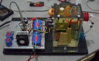
Overview of whole PS, Canola oil filled flyback tank on right, configured with ball spark gap.
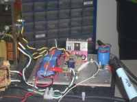
Flyback oil tank (left), Main caps in blue, circuit board.
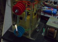
Hot arc.
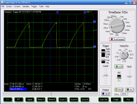
Current profile through flyback and 0.5 Ohm resistor, (Primary current), peaks at 5.8 V, so 5.8V / 0.5 Ohms = 11.6 peak amps.
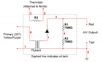
Oil tank schematic.
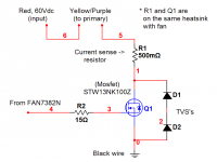
Power chopping circuit.
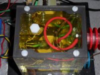
97degrees F, at the top surface of the acrylic tank. The small bubbles on the center and left are from the heat of expansion from oil filling the now hot ferrite gap, the larger bubble on right is for thermal expansion of the oil, the air bubble shrunk about 0.2 inches in overall diameter while at 97 degree F (ferrite is at 118 peak temp F). Time to let it cool off. I do worry that the pressure will blow out the gasket sealer. I may have to replace the four nylon screws with metal screws.
New pics, case is nearing completion.
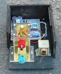
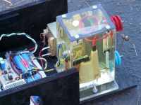
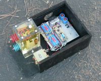
Re: HV Flyback Bench Top Power Supply for Lab.
radhoo, Fri Jul 22 2011, 08:49AM
Good initiative, but why did you submerge the flyback under oil? I see no advantages other than lowering the temperature on heavy loads.
radhoo, Fri Jul 22 2011, 08:49AM
Good initiative, but why did you submerge the flyback under oil? I see no advantages other than lowering the temperature on heavy loads.
Re: HV Flyback Bench Top Power Supply for Lab.
Patrick, Fri Jul 22 2011, 09:01AM
Patrick, Fri Jul 22 2011, 09:01AM
radhoo wrote ...
Good initiative, but why did you submerge the flyback under oil? I see no advantages other than lowering the temperature on heavy loads.
Yes, to keep it cool..Good initiative, but why did you submerge the flyback under oil? I see no advantages other than lowering the temperature on heavy loads.
Re: HV Flyback Bench Top Power Supply for Lab.
radhoo, Fri Jul 22 2011, 11:06AM
In my tests I've seen that is MUCH better to use concentric primary and secondary coils in a flyback. In this case you would have obtained better energy transfer and larger arcs using one of the primary original windings.
Also since this is a lab supply, why not use a HV resistor to get a feedback from the output, to regulate the output?
Re: HV Flyback Bench Top Power Supply for Lab.
Proud Mary, Fri Jul 22 2011, 03:23PM
Absolutely, Radu. I've found that by using the drive circuitry for which an LOPT was originally designed, that hundreds of hours of trouble-free continuous operation results.
Proud Mary, Fri Jul 22 2011, 03:23PM
radhoo wrote ...
In my tests I've seen that is MUCH better to use concentric primary and secondary coils in a flyback.
In my tests I've seen that is MUCH better to use concentric primary and secondary coils in a flyback.
Absolutely, Radu. I've found that by using the drive circuitry for which an LOPT was originally designed, that hundreds of hours of trouble-free continuous operation results.
Re: HV Flyback Bench Top Power Supply for Lab.
Patrick, Fri Jul 22 2011, 04:41PM
Patrick, Fri Jul 22 2011, 04:41PM
Proud Mary wrote ...
Absolutely, Radu. I've found that by using the drive circuitry for which an LOPT was originally designed, that hundreds of hours of trouble-free continuous operation results.
I have 3 flybacks of the same type, ill trythe original primary then and well see if theres a difference. Arnt the normal primaries meant to run off 90 or more volts though? if i could find a schematic that would make it easier.radhoo wrote ...
In my tests I've seen that is MUCH better to use concentric primary and secondary coils in a flyback.
In my tests I've seen that is MUCH better to use concentric primary and secondary coils in a flyback.
Absolutely, Radu. I've found that by using the drive circuitry for which an LOPT was originally designed, that hundreds of hours of trouble-free continuous operation results.
Re: HV Flyback Bench Top Power Supply for Lab.
Proud Mary, Fri Jul 22 2011, 06:02PM
Generally between 90 & 110V.
Here is a typical basic circuit:
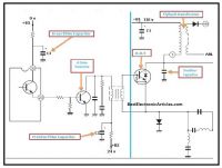
Proud Mary, Fri Jul 22 2011, 06:02PM
Patrick wrote ...
Proud Mary wrote ...
Absolutely, Radu. I've found that by using the drive circuitry for which an LOPT was originally designed, that hundreds of hours of trouble-free continuous operation results.
Arnt the normal primaries meant to run off 90 or more volts though? if i could find a schematic that would make it easier.radhoo wrote ...
In my tests I've seen that is MUCH better to use concentric primary and secondary coils in a flyback.
In my tests I've seen that is MUCH better to use concentric primary and secondary coils in a flyback.
Absolutely, Radu. I've found that by using the drive circuitry for which an LOPT was originally designed, that hundreds of hours of trouble-free continuous operation results.
Generally between 90 & 110V.
Here is a typical basic circuit:

Re: HV Flyback Bench Top Power Supply for Lab.
Patrick, Fri Jul 22 2011, 06:08PM
New pics!!!


Patrick, Fri Jul 22 2011, 06:08PM
Proud Mary wrote ...
Generally between 90 & 110V.
Here is a typical basic circuit:

ill try the original primary, but its hard to figure out, there are 8 different pin combinations which reveal 0.3 to 0.6 ohms, and Killa-X and i have no way of knowing the number type.Patrick wrote ...
Proud Mary wrote ...
Absolutely, Radu. I've found that by using the drive circuitry for which an LOPT was originally designed, that hundreds of hours of trouble-free continuous operation results.
Arnt the normal primaries meant to run off 90 or more volts though? if i could find a schematic that would make it easier.radhoo wrote ...
In my tests I've seen that is MUCH better to use concentric primary and secondary coils in a flyback.
In my tests I've seen that is MUCH better to use concentric primary and secondary coils in a flyback.
Absolutely, Radu. I've found that by using the drive circuitry for which an LOPT was originally designed, that hundreds of hours of trouble-free continuous operation results.
Generally between 90 & 110V.
Here is a typical basic circuit:

New pics!!!


Re: HV Flyback Bench Top Power Supply for Lab.
Proud Mary, Fri Jul 22 2011, 06:13PM
Are there no numbers on the LOPTs that we could cross-reference in the HR Diemen catalogue?
Added afterthought: it isn't unusual for an LOPT primary to have several auto-transformer taps on it - the idea with modern LOPT design is to supply power to as many sub-circuits of the whole TV or monitor as possible.
Proud Mary, Fri Jul 22 2011, 06:13PM
Patrick wrote ...
ill try the original primary, but its hard to figure out, there are 8 different pin combinations which reveal 0.3 to 0.6 ohms, and Killa-X and i have no way of knowing the number type.
ill try the original primary, but its hard to figure out, there are 8 different pin combinations which reveal 0.3 to 0.6 ohms, and Killa-X and i have no way of knowing the number type.
Are there no numbers on the LOPTs that we could cross-reference in the HR Diemen catalogue?
Added afterthought: it isn't unusual for an LOPT primary to have several auto-transformer taps on it - the idea with modern LOPT design is to supply power to as many sub-circuits of the whole TV or monitor as possible.
Re: HV Flyback Bench Top Power Supply for Lab.
Patrick, Fri Jul 22 2011, 06:16PM
From PM, Killa-X :
"I wont know anymore about them than you would, seeing i bought them on ebay as a "Factory Outlet" meaning, my spend on 24, all 24 could have been dead. they are all rejects for whatever reason. At least, thats what the seller claims. All 24 do work. I only had 3 that came shipped with 100% smashed cores.
I have tried searching the info on them with whats listed and found nothing sadly. Says TCE 70234 Feb 205 2:01
then theres a ba code. My phone says its:
70234509789660 which brings nothing on google."
My label says :
2G25023 A1A
TCE 35.0 Kv
RXE
Patrick, Fri Jul 22 2011, 06:16PM
Proud Mary wrote ...
Are there no numbers on the LOPTs that we could cross-reference in the HR Diemen catalogue?
Patrick wrote ...
ill try the original primary, but its hard to figure out, there are 8 different pin combinations which reveal 0.3 to 0.6 ohms, and Killa-X and i have no way of knowing the number type.
ill try the original primary, but its hard to figure out, there are 8 different pin combinations which reveal 0.3 to 0.6 ohms, and Killa-X and i have no way of knowing the number type.
Are there no numbers on the LOPTs that we could cross-reference in the HR Diemen catalogue?
From PM, Killa-X :
"I wont know anymore about them than you would, seeing i bought them on ebay as a "Factory Outlet" meaning, my spend on 24, all 24 could have been dead. they are all rejects for whatever reason. At least, thats what the seller claims. All 24 do work. I only had 3 that came shipped with 100% smashed cores.
I have tried searching the info on them with whats listed and found nothing sadly. Says TCE 70234 Feb 205 2:01
then theres a ba code. My phone says its:
70234509789660 which brings nothing on google."
My label says :
2G25023 A1A
TCE 35.0 Kv
RXE
Re: HV Flyback Bench Top Power Supply for Lab.
Proud Mary, Fri Jul 22 2011, 06:23PM
I'll have a look for you later, but right now I have to make some Wiener schnitzels.
Proud Mary, Fri Jul 22 2011, 06:23PM
Patrick wrote ...
From PM, Killa-X :
"I wont know anymore about them than you would, seeing i bought them on ebay as a "Factory Outlet" meaning, my spend on 24, all 24 could have been dead. they are all rejects for whatever reason. At least, thats what the seller claims. All 24 do work. I only had 3 that came shipped with 100% smashed cores.
I have tried searching the info on them with whats listed and found nothing sadly. Says TCE 70234 Feb 205 2:01
then theres a ba code. My phone says its:
70234509789660 which brings nothing on google."
My label says :
2G25023 A1A
TCE 35.0 Kv
RXE
Proud Mary wrote ...
Are there no numbers on the LOPTs that we could cross-reference in the HR Diemen catalogue?
Patrick wrote ...
ill try the original primary, but its hard to figure out, there are 8 different pin combinations which reveal 0.3 to 0.6 ohms, and Killa-X and i have no way of knowing the number type.
ill try the original primary, but its hard to figure out, there are 8 different pin combinations which reveal 0.3 to 0.6 ohms, and Killa-X and i have no way of knowing the number type.
Are there no numbers on the LOPTs that we could cross-reference in the HR Diemen catalogue?
From PM, Killa-X :
"I wont know anymore about them than you would, seeing i bought them on ebay as a "Factory Outlet" meaning, my spend on 24, all 24 could have been dead. they are all rejects for whatever reason. At least, thats what the seller claims. All 24 do work. I only had 3 that came shipped with 100% smashed cores.
I have tried searching the info on them with whats listed and found nothing sadly. Says TCE 70234 Feb 205 2:01
then theres a ba code. My phone says its:
70234509789660 which brings nothing on google."
My label says :
2G25023 A1A
TCE 35.0 Kv
RXE
I'll have a look for you later, but right now I have to make some Wiener schnitzels.
Re: HV Flyback Bench Top Power Supply for Lab.
Patrick, Fri Jul 22 2011, 06:26PM
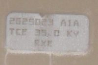
Label on flyback, I wonder if thats a ZERO or "O"...
2G25023 A1A
TCE 35.0 Kv
RXE
Second label says : TCE 70234 then date code 2005 02:10, (definately zeros).
Patrick, Fri Jul 22 2011, 06:26PM

Label on flyback, I wonder if thats a ZERO or "O"...
2G25023 A1A
TCE 35.0 Kv
RXE
Second label says : TCE 70234 then date code 2005 02:10, (definately zeros).
Re: HV Flyback Bench Top Power Supply for Lab.
Patrick, Fri Jul 22 2011, 06:39PM
Im thinking its this one:

2G25023 A1A, but remember Proud Mary i only have about 57 Volts at 4 amps available, im thinking pin 6 and pin 8.
(20 - 85 = 65v)
It sure seems to be the right one, Pin 7 is the Ground im using.
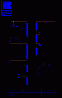
EDIT: what does the text block at the bottom mean?
Patrick, Fri Jul 22 2011, 06:39PM
Im thinking its this one:

2G25023 A1A, but remember Proud Mary i only have about 57 Volts at 4 amps available, im thinking pin 6 and pin 8.
(20 - 85 = 65v)
It sure seems to be the right one, Pin 7 is the Ground im using.
EDIT: what does the text block at the bottom mean?
Re: HV Flyback Bench Top Power Supply for Lab.
Proud Mary, Fri Jul 22 2011, 08:40PM
It refers to readings on the HR Diemen Simulator STVDST-01 test set for 15 kHz diode split transformers (DST)

MAT is certainly the ouput voltage in kV, but I'm not confident about the other values - "+" may be the output current in mA, which would make this into an LOPT of prodigious size.
I have to do the dishes now, but will look in again later.
Proud Mary, Fri Jul 22 2011, 08:40PM
Patrick wrote ...
EDIT: what does the text block at the bottom mean?
EDIT: what does the text block at the bottom mean?
It refers to readings on the HR Diemen Simulator STVDST-01 test set for 15 kHz diode split transformers (DST)

MAT is certainly the ouput voltage in kV, but I'm not confident about the other values - "+" may be the output current in mA, which would make this into an LOPT of prodigious size.
I have to do the dishes now, but will look in again later.
Re: HV Flyback Bench Top Power Supply for Lab.
Patrick, Fri Jul 22 2011, 08:50PM
After doing some math i believe im putting in 300W (AC input), and getting 181W out (at the arc) which is 60% eff. I think thats credible, im sure if i reduce the magnitizing current by using the internal primary i could up the efficiency and output power with no increase in input power.
Ill need to verify all this with an HV resistive divider which im building now.
Patrick, Fri Jul 22 2011, 08:50PM
Proud Mary wrote ...
I have to do the dishes now, but will look in again later.
How were the dogs?I have to do the dishes now, but will look in again later.
After doing some math i believe im putting in 300W (AC input), and getting 181W out (at the arc) which is 60% eff. I think thats credible, im sure if i reduce the magnitizing current by using the internal primary i could up the efficiency and output power with no increase in input power.
Ill need to verify all this with an HV resistive divider which im building now.
Re: HV Flyback Bench Top Power Supply for Lab.
Patrick, Fri Jul 22 2011, 08:57PM
EDIT: Crap, I double posted.
MAT = 46kV !!!!!!!!!!!!!!!!!!!!!!!!!!!!!!!!!!!!!! wholly--chit !!!!!!!!!!!
Patrick, Fri Jul 22 2011, 08:57PM
EDIT: Crap, I double posted.
Proud Mary wrote ...
It refers to readings on the HR Diemen Simulator STVDST-01 test set for 15 kHz diode split transformers (DST)
MAT is certainly the ouput voltage in kV, but I'm not confident about the other values
Patrick wrote ...
EDIT: what does the text block at the bottom mean?
EDIT: what does the text block at the bottom mean?
It refers to readings on the HR Diemen Simulator STVDST-01 test set for 15 kHz diode split transformers (DST)
MAT is certainly the ouput voltage in kV, but I'm not confident about the other values
MAT = 46kV !!!!!!!!!!!!!!!!!!!!!!!!!!!!!!!!!!!!!! wholly--chit !!!!!!!!!!!
Re: HV Flyback Bench Top Power Supply for Lab.
Proud Mary, Fri Jul 22 2011, 09:47PM
Dönberg are listing HR 6329 as the HR equivalent of 2G25023, though I see HR Diemen itself has dropped it from their product list - only to be expected as CRTs fade from the TV and monitor retail sector.
I've never seen an LOPT with these specs, and it's unusual that there is no focus output after the first diode up from Earth.
Someone else has stuck on that 35 kV sticker - I've seen plenty of HR LOPTs and the voltage is never stated on the outside - BUT - it is possible that it may have been done to meet some national (US?) safety certification scheme. Anyway, it's a lower figure than the datasheet MAT.
Look at the voltage on the primary auto tap - 850 Vpp. Never seen the likes of it, Patrick, but I'm sure that some of our resident flyback enthusiasts (not me!) will be able to tell you all about it.

Re: HV Flyback Bench Top Power Supply for Lab.
Patrick, Fri Jul 22 2011, 09:51PM
What do you think of me using the pins 6 and 8 as my 65 V primary?
On a seperate note, ill be using my Russian HV resistors for the divider, two 25 kv ones, so 46Kv at 70W, into reistors meant for 4 watts total, i hope this is ok for 1 to 3 seconds at a time? ill have them in oil of course.
PS. its the biggest Flyback ive seen in quite a while, about 11 years ago i ran into one almost as big from the largest CRT TV my family ever bought. So it must be a real piggie, its the size of a potato!
Patrick, Fri Jul 22 2011, 09:51PM
Proud Mary wrote ...
Dönberg are listing HR 6329 as the HR equivalent of 2G25023, though I see HR Diemen itself has dropped it from their product list - only to be expected as CRTs fade from the TV and monitor retail sector.
I've never seen an LOPT with these specs, and it's unusual that there is no focus output after the first diode up from Earth.
Someone else has stuck on that 35 kV sticker - I've seen plenty of HR LOPTs and the voltage is never stated on the outside - BUT - it is possible that it may have been done to meet some national (US?) safety certification scheme. Anyway, it's a lower figure than the datasheet MAT.
Look at the voltage on the primary auto tap - 850 Vpp. Never seen the likes of it, Patrick, but I'm sure that some of our resident flyback enthusiasts (not me!) will be able to tell you all about it.
Yep, ok ill wait for the oppinions to come pouring in...Dönberg are listing HR 6329 as the HR equivalent of 2G25023, though I see HR Diemen itself has dropped it from their product list - only to be expected as CRTs fade from the TV and monitor retail sector.
I've never seen an LOPT with these specs, and it's unusual that there is no focus output after the first diode up from Earth.
Someone else has stuck on that 35 kV sticker - I've seen plenty of HR LOPTs and the voltage is never stated on the outside - BUT - it is possible that it may have been done to meet some national (US?) safety certification scheme. Anyway, it's a lower figure than the datasheet MAT.
Look at the voltage on the primary auto tap - 850 Vpp. Never seen the likes of it, Patrick, but I'm sure that some of our resident flyback enthusiasts (not me!) will be able to tell you all about it.

What do you think of me using the pins 6 and 8 as my 65 V primary?
On a seperate note, ill be using my Russian HV resistors for the divider, two 25 kv ones, so 46Kv at 70W, into reistors meant for 4 watts total, i hope this is ok for 1 to 3 seconds at a time? ill have them in oil of course.
PS. its the biggest Flyback ive seen in quite a while, about 11 years ago i ran into one almost as big from the largest CRT TV my family ever bought. So it must be a real piggie, its the size of a potato!
Re: HV Flyback Bench Top Power Supply for Lab.
Killa-X, Fri Jul 22 2011, 10:04PM
Hopefully you get things figured with the pins. I have always ran them from the core, never the internal windings. But good luck! I have a flyback from a rear projection screen that is 2X the size of these, with a voltage multiplier. However, it has horrible arcs because the pins are too close and flash over.
Re: HV Flyback Bench Top Power Supply for Lab.
Proud Mary, Fri Jul 22 2011, 10:11PM
Are these 1GΩ each ?
Proud Mary, Fri Jul 22 2011, 10:11PM
Patrick wrote ...
On a seperate note, ill be using my Russian HV resistors for the divider, two 25 kv ones, so 46Kv at 70W, into reistors meant for 4 watts total, i hope this is ok for 1 to 3 seconds at a time? ill have them in oil of course.
On a seperate note, ill be using my Russian HV resistors for the divider, two 25 kv ones, so 46Kv at 70W, into reistors meant for 4 watts total, i hope this is ok for 1 to 3 seconds at a time? ill have them in oil of course.
Are these 1GΩ each ?
Re: HV Flyback Bench Top Power Supply for Lab.
Patrick, Fri Jul 22 2011, 10:17PM

The pins 6 and 8 have a smaller wire awg than the 2 and 12 pins, but pins 6 and8 have the lowest reistance at 0.2 ohms others are at 0.4-0.6 ohms, so the primary of pins 6 and 8 would dissipate 5 watts given the switching wave as it is now.
Patrick, Fri Jul 22 2011, 10:17PM
Proud Mary wrote ...
Are these 1GΩ each ?
Each one is 15Mohm, 25kV, 2 watts, 5 inches long, tiger stripe with aluminum oxide core .3 inches in diameter. Id use two in series. thus 50Kv at 4 Watts as per the spec...Are these 1GΩ each ?
Killa-X wrote ...
Hopefully you get things figured with the pins. I have always ran them from the core, never the internal windings. But good luck! I have a flyback from a rear projection screen that is 2X the size of these, with a voltage multiplier. However, it has horrible arcs because the pins are too close and flash over.
Killa-X, Would you like to join the oil insulating mafia? I know a guy. Hopefully you get things figured with the pins. I have always ran them from the core, never the internal windings. But good luck! I have a flyback from a rear projection screen that is 2X the size of these, with a voltage multiplier. However, it has horrible arcs because the pins are too close and flash over.

The pins 6 and 8 have a smaller wire awg than the 2 and 12 pins, but pins 6 and8 have the lowest reistance at 0.2 ohms others are at 0.4-0.6 ohms, so the primary of pins 6 and 8 would dissipate 5 watts given the switching wave as it is now.
Re: HV Flyback Bench Top Power Supply for Lab.
Proud Mary, Fri Jul 22 2011, 10:29PM
Maybe you should consider XL @ 15 kHz, rather than R, when comparing the different winding options. So measure those inductances...
Proud Mary, Fri Jul 22 2011, 10:29PM
Maybe you should consider XL @ 15 kHz, rather than R, when comparing the different winding options. So measure those inductances...
Re: HV Flyback Bench Top Power Supply for Lab.
Patrick, Fri Jul 22 2011, 10:33PM
I killed my LCR meter (BK precision 875B), so i cant maesure X sub L.
Patrick, Fri Jul 22 2011, 10:33PM
I killed my LCR meter (BK precision 875B), so i cant maesure X sub L.
Re: HV Flyback Bench Top Power Supply for Lab.
Proud Mary, Fri Jul 22 2011, 10:41PM
Thinking about that 850 Vpp auto tap on the primary, you can expect quite a bit of back EMF looking for weaknesses in your driver circuit
Proud Mary, Fri Jul 22 2011, 10:41PM
Thinking about that 850 Vpp auto tap on the primary, you can expect quite a bit of back EMF looking for weaknesses in your driver circuit
Re: HV Flyback Bench Top Power Supply for Lab.
Patrick, Fri Jul 22 2011, 11:27PM
The flyback (and the bottom pins) itself is pretty well insulated with the addition of epoxy and oil, so ill eat your best top hat if a spark or arc develops from the bottom pins... the semi's however are always a questin mark though.
EDIT: ive got the transistor/ heat sink up too 156 degree F... core to 110 F.
EDIT: the fall time (100% to 0%) seems to be between 800 nS and 1.2 uS i could probaly do better with a lower gate resistance.
EDIT: Fall time is 1.1uS (100% to 10%), so that gate drive IC is really working, as the 555 was only capable of 3.8 uS when directly connected to the gate.
New pic...

97degrees F, at the top surface of the acrylic tank. The small bubbles on the center and left are from the heat of expansion from oil filling the now hot ferrite gap, the larger bubble on right is for thermal expansion of the oil, the air bubble shrunk about 0.2 inches in overall diameter while at 97 degree F (ferrite is at 118 peak temp F). Time to let it cool off. I do worry that the pressure will blow out the gasket sealer.
EDIT: Its 9 PM, im too tired to continue, ive captured "a" high voltage scope screen shot, not sure how credible it is though. Shorted out the main capbank 4000uF @ 82 Volts across the drain-source, whole apartment smells like burned metal, oscilloscope was undamaged, im unharmed but pisst off. Im done for the night, time to drink new castle.
Whoops it just gave up the purple smoke! MOSFET is definitely KIA, had another 20 seconds of run time before it finnally died. Apartment stinks even more now. I had 12, 11 left now.
EDIT: 11:43 PM totally drunk right noW, no more hV for me. I have new pics to post.
HV scope pics...
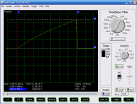
Current pulse, zoomed in. 6.6V means 6.6V / 0.5Ohms = 13.2 amps.
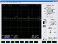
Average at 10.8 kV (1000:1 Probe, 30.6M ohms) I have no idea if this is credible or bogus.
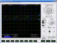
Peak at 24.4kV (1000:1 probe, 30.6 Mohms) I have no idea if this is credible or bogus.
_________________________________________ ___________________________________________
EDIT: 1:03AM .... neEd sLeEp....ZzZZzzzzzZzzZZZzZzzz....
Does any one know what a flyback output looks like on scope?
maybe on the last page of this PDF?
]flybackscope.pdf[/file]
From the above PDF and my Screen caps...
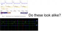
_________________________________________________ ___________________________________
>>>
Patrick, Fri Jul 22 2011, 11:27PM
Proud Mary wrote ...
Thinking about that 850 Vpp auto tap on the primary, you can expect quite a bit of back EMF looking for weaknesses in your driver circuit
Well ill up the gate protection then, my mosfet can handle 1000V, but Its TVSed down to 600V, STmicro always puts double zeners across the gate, but ill use a TVS there too.Thinking about that 850 Vpp auto tap on the primary, you can expect quite a bit of back EMF looking for weaknesses in your driver circuit
The flyback (and the bottom pins) itself is pretty well insulated with the addition of epoxy and oil, so ill eat your best top hat if a spark or arc develops from the bottom pins... the semi's however are always a questin mark though.
EDIT: ive got the transistor/ heat sink up too 156 degree F... core to 110 F.
EDIT: the fall time (100% to 0%) seems to be between 800 nS and 1.2 uS i could probaly do better with a lower gate resistance.
EDIT: Fall time is 1.1uS (100% to 10%), so that gate drive IC is really working, as the 555 was only capable of 3.8 uS when directly connected to the gate.
New pic...

97degrees F, at the top surface of the acrylic tank. The small bubbles on the center and left are from the heat of expansion from oil filling the now hot ferrite gap, the larger bubble on right is for thermal expansion of the oil, the air bubble shrunk about 0.2 inches in overall diameter while at 97 degree F (ferrite is at 118 peak temp F). Time to let it cool off. I do worry that the pressure will blow out the gasket sealer.
EDIT: Its 9 PM, im too tired to continue, ive captured "a" high voltage scope screen shot, not sure how credible it is though. Shorted out the main capbank 4000uF @ 82 Volts across the drain-source, whole apartment smells like burned metal, oscilloscope was undamaged, im unharmed but pisst off. Im done for the night, time to drink new castle.
Whoops it just gave up the purple smoke! MOSFET is definitely KIA, had another 20 seconds of run time before it finnally died. Apartment stinks even more now. I had 12, 11 left now.
EDIT: 11:43 PM totally drunk right noW, no more hV for me. I have new pics to post.
HV scope pics...

Current pulse, zoomed in. 6.6V means 6.6V / 0.5Ohms = 13.2 amps.

Average at 10.8 kV (1000:1 Probe, 30.6M ohms) I have no idea if this is credible or bogus.

Peak at 24.4kV (1000:1 probe, 30.6 Mohms) I have no idea if this is credible or bogus.
_________________________________________ ___________________________________________
EDIT: 1:03AM .... neEd sLeEp....ZzZZzzzzzZzzZZZzZzzz....
Does any one know what a flyback output looks like on scope?
maybe on the last page of this PDF?
]flybackscope.pdf[/file]
From the above PDF and my Screen caps...

_________________________________________________ ___________________________________
>>>
Re: HV Flyback Bench Top Power Supply for Lab.
Patrick, Sat Jul 23 2011, 10:43PM
All systems fixed, fully functioning now including fan and new Logic power cap. it wasnt the transistor that blew-out last night, it was the power resistor 0.5 ohm, stunk like hell.
EDIT: I think im boiling the oil around the primary, bubbles appear after 20 secs, and top of acrylic was warm, i think im pulling more current... the duty cycle is 53% now, i want to reduce it to 33% for heat control.
EDIT: Yep, boiling oil, i can see a hot stream of oil floating upward.
Re: HV Flyback Bench Top Power Supply for Lab.
Patrick, Tue Jul 26 2011, 09:46PM
Ive decided to mod the primary as radhoo and ProudMary have previously pointed out. i will use pins 6 and 8 as my new primary, which is meant to see 65V. Ill be suppling 55-59V but im hoping the internal primaries reactance will limit the current to a value that wont cuase the oil to boil. If not, then ill turn the duty cycle down from 53% on to 33% on, for heat control.
EDIT: OOps I just blew the main resistor, the internal primary is way better at voltage and power. But I may have to ballast the primary with an external resistor, maybe in the oil tank.
EDIT: I have done the math, i now believe if i reduce the duty cycle from 53% to 40% reduces the power applied by 50%.... so ill try that tomorrow.
Re: HV Flyback Bench Top Power Supply for Lab.
Proud Mary, Wed Jul 27 2011, 08:51AM
How about a nice little thermal shutdown feature?
Proud Mary, Wed Jul 27 2011, 08:51AM
Patrick wrote ...
Ive decided to mod the primary as radhoo and ProudMary have previously pointed out. i will use pins 6 and 8 as my new primary, which is meant to see 65V. Ill be suppling 55-59V but im hoping the internal primaries reactance will limit the current to a value that wont cuase the oil to boil. If not, then ill turn the duty cycle down from 53% on to 33% on, for heat control.
EDIT: OOps I just blew the main resistor, the internal primary is way better at voltage and power. But I may have to ballast the primary with an external resistor, maybe in the oil tank.
EDIT: I have done the math, i now believe if i reduce the duty cycle from 53% to 40% reduces the power applied by 50%.... so ill try that tomorrow.
How about a nice little thermal shutdown feature?
Re: HV Flyback Bench Top Power Supply for Lab.
Patrick, Wed Jul 27 2011, 09:21AM
Im about to add that kind of feature in Gen 2 but the sparks and bad smell occured this time in just 2 seconds. So, i dont think a thermal interupt would be fast enough to intervene. Id really need pulse by pulse current limit on the order off 30-60uS.
EDIT: The 55 Volt pin 6 and pin 8 primary works well, definitley higher voltage.
Patrick, Wed Jul 27 2011, 09:21AM
Proud Mary wrote ...
How about a nice little thermal shutdown feature?
How about a nice little thermal shutdown feature?
Im about to add that kind of feature in Gen 2 but the sparks and bad smell occured this time in just 2 seconds. So, i dont think a thermal interupt would be fast enough to intervene. Id really need pulse by pulse current limit on the order off 30-60uS.
EDIT: The 55 Volt pin 6 and pin 8 primary works well, definitley higher voltage.
Re: HV Flyback Bench Top Power Supply for Lab.
Patrick, Fri Jul 29 2011, 08:26AM
New pics, case is nearing completion.


Patrick, Fri Jul 29 2011, 08:26AM
New pics, case is nearing completion.


Re: HV Flyback Bench Top Power Supply for Lab.
Patrick, Fri Oct 07 2011, 06:25AM
Case mods have already been made: Clear top, new fan, larger heatsink, new logic PS.
I may switch over from the 555+7382 combination, over to the UC3526.
More modding and pics to come!
Patrick, Fri Oct 07 2011, 06:25AM
Case mods have already been made: Clear top, new fan, larger heatsink, new logic PS.
I may switch over from the 555+7382 combination, over to the UC3526.
More modding and pics to come!
Re: HV Flyback Bench Top Power Supply for Lab.
Patrick, Sat Oct 08 2011, 10:53PM
Need help on this... I cant get the Black text " Danger: High Voltage " to turn white on that red field,it just prints blacktext no matter what i change.
Any help please.. Im using AutoCAD 2007.
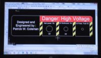
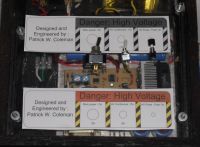
I need to spell check before the final proof print.
EDIT: fixed it!
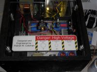
LAbel looks real good, the JPEGification kinda spoils it in this pic though.
Patrick, Sat Oct 08 2011, 10:53PM
Need help on this... I cant get the Black text " Danger: High Voltage " to turn white on that red field,it just prints blacktext no matter what i change.
Any help please.. Im using AutoCAD 2007.


I need to spell check before the final proof print.
EDIT: fixed it!

LAbel looks real good, the JPEGification kinda spoils it in this pic though.
Re: HV Flyback Bench Top Power Supply for Lab.
Inducktion, Sun Oct 09 2011, 02:21AM
Also, Patrick, could you PLEASE explain to me how you used the half bridge gate drive IC? I have the chip you used, as well as the beefier version FAN7392, (sinks and sources 3 amps) and I can never get them to work properly... Even when following the datasheet!
Inducktion, Sun Oct 09 2011, 02:21AM
Also, Patrick, could you PLEASE explain to me how you used the half bridge gate drive IC? I have the chip you used, as well as the beefier version FAN7392, (sinks and sources 3 amps) and I can never get them to work properly... Even when following the datasheet!
Re: HV Flyback Bench Top Power Supply for Lab.
Patrick, Sun Oct 09 2011, 02:51AM
ill post a schematic of my own device, BRB in an hour i got to eat.
EDIT:

This is the exact circuit i used for my single transistor flyback driver, If you bread board this we can see if it lights up a LED or something. ill talk you through it.
I used 1k pull down resistors on pins 2, 3 and 7.
Patrick, Sun Oct 09 2011, 02:51AM
Inducktion wrote ...
Also, Patrick, could you PLEASE explain to me how you used the half bridge gate drive IC? I have the chip you used, as well as the beefier version FAN7392, (sinks and sources 3 amps) and I can never get them to work properly... Even when following the datasheet!
You should have spoke up. Its easy to use. first they wont turn on below a certain voltage (UVLO) i think its 9 volts?Also, Patrick, could you PLEASE explain to me how you used the half bridge gate drive IC? I have the chip you used, as well as the beefier version FAN7392, (sinks and sources 3 amps) and I can never get them to work properly... Even when following the datasheet!
ill post a schematic of my own device, BRB in an hour i got to eat.
EDIT:

This is the exact circuit i used for my single transistor flyback driver, If you bread board this we can see if it lights up a LED or something. ill talk you through it.
I used 1k pull down resistors on pins 2, 3 and 7.
Re: HV Flyback Bench Top Power Supply for Lab.
Patrick, Sun Oct 09 2011, 06:07AM
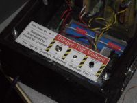
Face plate done! I hope i spelled weverything right, or ill be doing it again.
Patrick, Sun Oct 09 2011, 06:07AM
Face plate done! I hope i spelled weverything right, or ill be doing it again.

Re: HV Flyback Bench Top Power Supply for Lab.
Inducktion, Sun Oct 09 2011, 03:31PM
Oh, right, I forgot you were using to drive only one MOSFET.
I've never been able to get it to work right driving a half bridge, anyway. The high side just never wants to work!
Inducktion, Sun Oct 09 2011, 03:31PM
Patrick wrote ...
ill post a schematic of my own device, BRB in an hour i got to eat.
EDIT:

This is the exact circuit i used for my single transistor flyback driver, If you bread board this we can see if it lights up a LED or something. ill talk you through it.
I used 1k pull down resistors on pins 2, 3 and 7.
Inducktion wrote ...
Also, Patrick, could you PLEASE explain to me how you used the half bridge gate drive IC? I have the chip you used, as well as the beefier version FAN7392, (sinks and sources 3 amps) and I can never get them to work properly... Even when following the datasheet!
You should have spoke up. Its easy to use. first they wont turn on below a certain voltage (UVLO) i think its 9 volts?Also, Patrick, could you PLEASE explain to me how you used the half bridge gate drive IC? I have the chip you used, as well as the beefier version FAN7392, (sinks and sources 3 amps) and I can never get them to work properly... Even when following the datasheet!
ill post a schematic of my own device, BRB in an hour i got to eat.
EDIT:

This is the exact circuit i used for my single transistor flyback driver, If you bread board this we can see if it lights up a LED or something. ill talk you through it.
I used 1k pull down resistors on pins 2, 3 and 7.
Oh, right, I forgot you were using to drive only one MOSFET.
I've never been able to get it to work right driving a half bridge, anyway. The high side just never wants to work!
Re: HV Flyback Bench Top Power Supply for Lab.
Patrick, Sun Oct 09 2011, 04:12PM
Are you using a push-pull CT, or the half bridge? one is easier then the other.
Lets start a thead in the HV section. label it FAN7382N or something.
Patrick, Sun Oct 09 2011, 04:12PM
Inducktion wrote ...
Oh, right, I forgot you were using to drive only one MOSFET.
I've never been able to get it to work right driving a half bridge, anyway. The high side just never wants to work!
We can fix that, whats your schematic look like? both my channels work, if you need the boot strap deal then you may need better components (if the high side doesnt work im suspicous its your boot PS that the problem.)Oh, right, I forgot you were using to drive only one MOSFET.
I've never been able to get it to work right driving a half bridge, anyway. The high side just never wants to work!
Are you using a push-pull CT, or the half bridge? one is easier then the other.
Lets start a thead in the HV section. label it FAN7382N or something.
Re: HV Flyback Bench Top Power Supply for Lab.
Patrick, Tue Dec 13 2011, 01:27AM
Ok mods and fixes complete.
accidental 4 inch arc flash to LV electronics, killed main MOSFET, both TVS's, Bridge rectifier, and my best transformer got smoked.
(Patrick <- depressed)
Ok having topped off the oil, so that 4 inch gap is now oil-not air, replaced and scoped all new semi's. interestingly enough the FAN7382 survived! (i hope it isnt one of the "zombie undead" semi's, that fail a few hours after overvolting.)
Ok the new flyback is installed, this time using the internal primary, meant for 65V, i currently drive it at 78 no load Volts. im sure theres some droop though once current starts getting switched. I should be switching 2 amps average and 4 amps peak throught the primary at about 70 volts.
It arcs every time continuosly across a gap of 1.2 inches and sparks to 1.4 inches intermitenly, in both cases gap electrodes are 0.44 inch dia. ball bearings.
Im thinking the HV out is 37 kV, at maybe 3-4 mA. so about 160 Watts.
Also, for my carbon fiber lifter, ill have to use a main gap of 2.5 or more inches.
EDIT: with no arcs or sparks present, and loaded only with my 10,000:1 Oscope probe (375 Mohm) it reads only 21kV !?
Re: HV Flyback Bench Top Power Supply for Lab.
Patrick, Tue Dec 20 2011, 05:55AM
Ok ive been having problems since the lo voltage side got hit with a 40kV spark.
ive gone through several of my precious STW13NK100Z's MOSFETs, even though before that bad spark i had not had a single mosfet fail. all of them failed the same way 0.01 ohms beteen all three pins, so i believe this indicates overvolting, not overcurrenting.
Until resolved im swithcing over to my cheaper more numerous HGTG7N60A4D IGBTs, this pic shows my new mods...
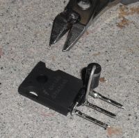
600 Volt IGBT, with a 300 volt unidirectional TVS from C to E, and an 18 volt bi-directional TVS from G to E... if this blows i dont know what else to try...
Gate drive appears to be way to low, like 3 volts, dont know why though.
I am seriously considering re-engineering the whole dam thing, getting rid of the 555 + FAN7382 and going with the UCC3526N. This will give me better wavform control then the 555, and current control.
Patrick, Tue Dec 20 2011, 05:55AM
Ok ive been having problems since the lo voltage side got hit with a 40kV spark.
ive gone through several of my precious STW13NK100Z's MOSFETs, even though before that bad spark i had not had a single mosfet fail. all of them failed the same way 0.01 ohms beteen all three pins, so i believe this indicates overvolting, not overcurrenting.
Until resolved im swithcing over to my cheaper more numerous HGTG7N60A4D IGBTs, this pic shows my new mods...

600 Volt IGBT, with a 300 volt unidirectional TVS from C to E, and an 18 volt bi-directional TVS from G to E... if this blows i dont know what else to try...
Gate drive appears to be way to low, like 3 volts, dont know why though.
I am seriously considering re-engineering the whole dam thing, getting rid of the 555 + FAN7382 and going with the UCC3526N. This will give me better wavform control then the 555, and current control.
Re: HV Flyback Bench Top Power Supply for Lab.
Patrick, Fri Dec 23 2011, 12:27AM
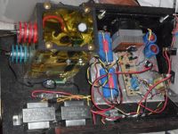
Pic update:
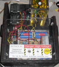
Mushroom HV momentary button added.
Patrick, Fri Dec 23 2011, 12:27AM
Pic update:

Mushroom HV momentary button added.

Re: HV Flyback Bench Top Power Supply for Lab.
Patrick, Fri Dec 30 2011, 09:21AM
Im definitely going to etch a new board, based on the UC28023D2 single switch CCM ic, which has a 0 to 90% duty cycle capability, and ill use a current transformer for cycle by cycle current limiting.
i may try primary side regulation, but thats experimental, ive never done this kind of regulation before.
Re: HV Flyback Bench Top Power Supply for Lab.
Steve Conner, Fri Dec 30 2011, 10:07AM
Jan Martis has a nice design for a flyback driver with one of those UC3842 type ICs. It has cycle by cycle limiting and an energy recovery snubber.
I lost the link, maybe he can supply it. I think he's Dr. Dark Current nowadays.
Steve Conner, Fri Dec 30 2011, 10:07AM
Jan Martis has a nice design for a flyback driver with one of those UC3842 type ICs. It has cycle by cycle limiting and an energy recovery snubber.
I lost the link, maybe he can supply it. I think he's Dr. Dark Current nowadays.
Re: HV Flyback Bench Top Power Supply for Lab.
Marko, Fri Dec 30 2011, 01:48PM
Hi guys here's the one I know off, not sure if it's his:

Marko, Fri Dec 30 2011, 01:48PM
Hi guys here's the one I know off, not sure if it's his:

Re: HV Flyback Bench Top Power Supply for Lab.
Patrick, Fri Dec 30 2011, 08:59PM
i was thinking of using a tertiary winding for the voltage regulation.
and this type of circuit...

I still have no idea how to calculate nodes, poles or any of the other feedback and compensation circuit stuff. Its a total mystery to me.
Patrick, Fri Dec 30 2011, 08:59PM
i was thinking of using a tertiary winding for the voltage regulation.
and this type of circuit...

I still have no idea how to calculate nodes, poles or any of the other feedback and compensation circuit stuff. Its a total mystery to me.
Re: HV Flyback Bench Top Power Supply for Lab.
Patrick, Sat Jan 14 2012, 07:38AM
here it is....there appears to be two variants, but i cant read his language....

Patrick, Sat Jan 14 2012, 07:38AM
Steve Conner wrote ...
Jan Martis has a nice design for a flyback driver with one of those UC3842 type ICs. It has cycle by cycle limiting and an energy recovery snubber.
I lost the link, maybe he can supply it. I think he's Dr. Dark Current nowadays.
Jan Martis has a nice design for a flyback driver with one of those UC3842 type ICs. It has cycle by cycle limiting and an energy recovery snubber.
I lost the link, maybe he can supply it. I think he's Dr. Dark Current nowadays.
here it is....there appears to be two variants, but i cant read his language....

Re: HV Flyback Bench Top Power Supply for Lab.
Pinky's Brain, Sat Jan 14 2012, 11:48AM
Why would you need to? The concept is clear from the schematics, the first is pure PWM ... the second is PWM with current limiting. Neither has voltage feedback though, so only the snubber design is useful to you.
Don't see why you would use a current transformer BTW. What is wrong with shunts under the MOSFET like this circuit?
PS. AFAICS this regenerative snubber is going to be ringy as hell, is going to make primary side feedback more difficult ...
Re: HV Flyback Bench Top Power Supply for Lab.
Patrick, Sat Jan 14 2012, 11:57AM
the problem with shunts is that they generate heat, i blew some of my 0.5 ohm ones out pretty easilly. id rather use a current transformer for that reason alone... also i need one for a 50 amp circuit i have coming up, so might as well learn now anyway.
EDIT: im thinking of using the 170 VDC from rectified mains for the primary and single switch to the flyback,i think pins 10 and 11 will be my new primary.
Im trying to develop a whole new series of power supplies that dont need any iron core line transformers, my radio shack ones are too expensive, weak, and they're heavy...
i may be able to just use rectified mains for the UC3526AN, the FAN4800IN, and the UC28023/and 5, and the UC3844N. still looking at the examples in the datasheets though.
Patrick, Sat Jan 14 2012, 11:57AM
Pinky's Brain wrote ...
Why would you need to? The concept is clear from the schematics, the first is pure PWM ... the second is PWM with current limiting. Neither has voltage feedback though, so only the snubber design is useful to you.
Don't see why you would use a current transformer BTW. What is wrong with shunts under the MOSFET like this circuit?
Im reading up on snubbers right now, from the TI/Unitrode PDF's. His is hard to figure out...Why would you need to? The concept is clear from the schematics, the first is pure PWM ... the second is PWM with current limiting. Neither has voltage feedback though, so only the snubber design is useful to you.
Don't see why you would use a current transformer BTW. What is wrong with shunts under the MOSFET like this circuit?
the problem with shunts is that they generate heat, i blew some of my 0.5 ohm ones out pretty easilly. id rather use a current transformer for that reason alone... also i need one for a 50 amp circuit i have coming up, so might as well learn now anyway.
EDIT: im thinking of using the 170 VDC from rectified mains for the primary and single switch to the flyback,i think pins 10 and 11 will be my new primary.
Im trying to develop a whole new series of power supplies that dont need any iron core line transformers, my radio shack ones are too expensive, weak, and they're heavy...
i may be able to just use rectified mains for the UC3526AN, the FAN4800IN, and the UC28023/and 5, and the UC3844N. still looking at the examples in the datasheets though.
Re: HV Flyback Bench Top Power Supply for Lab.
Pinky's Brain, Sat Jan 14 2012, 12:21PM
Pinky's Brain, Sat Jan 14 2012, 12:21PM
wrote ...
the problem with shunts is that they generate heat
With a correctly dimensioned exposed metal shunt in oil I'd think your transformer would fry long before the shunt.the problem with shunts is that they generate heat
Re: HV Flyback Bench Top Power Supply for Lab.
Patrick, Sat Jan 14 2012, 12:33PM
what do you mean metal shunt? what is your picture of? ive never seen that before... were not talking MOTS's here are we? im not.
EDIT: i still cant figure out how his snubber works there...
Patrick, Sat Jan 14 2012, 12:33PM
Pinky's Brain wrote ...
Wait...wait i think were talking about two different things, when i said "shunt", i meant a resistive current sense, for the cycle by cyle limit. wrote ...
the problem with shunts is that they generate heat
With a correctly dimensioned exposed metal shunt in oil I'd think your transformer would fry long before the shunt.the problem with shunts is that they generate heat
what do you mean metal shunt? what is your picture of? ive never seen that before... were not talking MOTS's here are we? im not.
EDIT: i still cant figure out how his snubber works there...
Re: HV Flyback Bench Top Power Supply for Lab.
Pinky's Brain, Sat Jan 14 2012, 02:10PM
It's a picture of a metal shunt for current sensing, it's basically nichrome resistance wire on steroids. Just search for shunt on digikey and look at the results in resistors and specialist resistors.
AFAICS the snubber transfers the energy from the primary leakage induction to the snubber capacitor when the MOSFET turns off (it doesn't keep ringing of course, I was wrong about that). When the MOSFET turns on the capacitor starts a partial oscillation with the inductor, initially the voltage at the right side of the capacitor will be negative, when it rings up with the inductor they can dump energy in the main power supply smoothing capacitor (ie. regeneration).
Re: HV Flyback Bench Top Power Supply for Lab.
Patrick, Sat Jan 14 2012, 02:18PM
Patrick, Sat Jan 14 2012, 02:18PM
Pinky's Brain wrote ...
AFAICS the snubber transfers the energy from the primary leakage induction to the snubber capacitor when the MOSFET turns off (it doesn't keep ringing of course, I was wrong about that). When the MOSFET turns on the capacitor starts a partial oscillation with the inductor, initially the voltage at the right side of the capacitor will be negative, when it rings up with the inductor they can dump energy in the main power supply smoothing capacitor (ie. regeneration).
excellent, ill try to simulate all this then, ZVS and ZCS are what im trying to use to ease the burden on my square wave switching MOSFET/PPCT transformers too.AFAICS the snubber transfers the energy from the primary leakage induction to the snubber capacitor when the MOSFET turns off (it doesn't keep ringing of course, I was wrong about that). When the MOSFET turns on the capacitor starts a partial oscillation with the inductor, initially the voltage at the right side of the capacitor will be negative, when it rings up with the inductor they can dump energy in the main power supply smoothing capacitor (ie. regeneration).
Re: HV Flyback Bench Top Power Supply for Lab.
Pinky's Brain, Sat Jan 14 2012, 02:37PM
You sure you want the headaches of ZVS/ZCS? The control schemes are not fixed frequency, and the standard ICs for them schemes aren't designed for transformers as lousy as high voltage transformers.
One way to reduce stress on the MOSFET is two switch flyback, Jan Martis's design is very elegant but to work it has to increase Vds above the power supply voltage. With a two switch design you can keep Vds at the same value as your power supply voltage.
Re: HV Flyback Bench Top Power Supply for Lab.
Patrick, Sat Jan 14 2012, 03:01PM
Patrick, Sat Jan 14 2012, 03:01PM
Pinky's Brain wrote ...
You sure you want the headaches of ZVS/ZCS? The control schemes are not fixed frequency, and the standard ICs for them schemes aren't designed for transformers as lousy as high voltage transformers.
One way to reduce stress on the MOSFET is two switch flyback, Jan Martis's design is very elegant but to work it has to increase Vds above the power supply voltage. With a two switch design you can keep Vds at the same value as your power supply voltage.
when i say ZCS/ZVS i mean making sure the voltage and curretn arnt present at the same time while the switching transsistions are occurring. i absolutley dont want to get into sine wave stuff.You sure you want the headaches of ZVS/ZCS? The control schemes are not fixed frequency, and the standard ICs for them schemes aren't designed for transformers as lousy as high voltage transformers.
One way to reduce stress on the MOSFET is two switch flyback, Jan Martis's design is very elegant but to work it has to increase Vds above the power supply voltage. With a two switch design you can keep Vds at the same value as your power supply voltage.
Re: HV Flyback Bench Top Power Supply for Lab.
Patrick, Sun Jan 15 2012, 10:07AM
I am trying to do the math on a current transformer, id like to use a single wire pass through for the primary (as i see many of you SSTC'ers do with your bridges) so do i consider this kind of primary a 1/2 turn?
ive been reading the TI/Unitrode stuff here -> but it doesnt say in this case.
im trying for a 40kHz, single switch forward waveform current detection.
Patrick, Sun Jan 15 2012, 10:07AM
I am trying to do the math on a current transformer, id like to use a single wire pass through for the primary (as i see many of you SSTC'ers do with your bridges) so do i consider this kind of primary a 1/2 turn?
ive been reading the TI/Unitrode stuff here ->
 but it doesnt say in this case.
im trying for a 40kHz, single switch forward waveform current detection.
Re: HV Flyback Bench Top Power Supply for Lab.
Patrick, Tue Jan 17 2012, 03:49AM
Ok here's what i mean when i say soft switching :
(Thus i can avoid the rancid, vile, vermin known as "sine waves".)
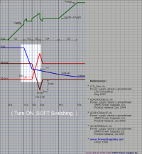
Square wave tuning ON. The voltage falls first, then the current rises.
(im thinking induction is needed for this purpose.)
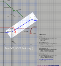
Sqaure wave turning OFF. The current falls first then the voltage rises. \
(im thinking capacitence is needed for this purpose.)
From this source...
Patrick, Tue Jan 17 2012, 03:49AM
Ok here's what i mean when i say soft switching :
(Thus i can avoid the rancid, vile, vermin known as "sine waves".)

Square wave tuning ON. The voltage falls first, then the current rises.
(im thinking induction is needed for this purpose.)

Sqaure wave turning OFF. The current falls first then the voltage rises. \
(im thinking capacitence is needed for this purpose.)
From this source...

Re: HV Flyback Bench Top Power Supply for Lab.
Patrick, Thu Jan 19 2012, 09:37AM
Important PDF on MOSFET and IGBT switching factors:
]00786a.pdf[/file]
]apt0403.pdf[/file]
Patrick, Thu Jan 19 2012, 09:37AM
Important PDF on MOSFET and IGBT switching factors:
]00786a.pdf[/file]
]apt0403.pdf[/file]
Re: HV Flyback Bench Top Power Supply for Lab.
Pinky's Brain, Fri Jan 20 2012, 09:25PM
I don't really see the point of soft switching unless you're worrying about EMI ... it heats up your switches ...
Pinky's Brain, Fri Jan 20 2012, 09:25PM
I don't really see the point of soft switching unless you're worrying about EMI ... it heats up your switches ...
Re: HV Flyback Bench Top Power Supply for Lab.
Patrick, Sat Jan 21 2012, 05:38AM
Patrick, Sat Jan 21 2012, 05:38AM
Pinky's Brain wrote ...
I don't really see the point of soft switching unless you're worrying about EMI ... it heats up your switches ...
really? buy V x I = P, it seems like they should run cooler.I don't really see the point of soft switching unless you're worrying about EMI ... it heats up your switches ...
Re: HV Flyback Bench Top Power Supply for Lab.
Pinky's Brain, Sat Jan 21 2012, 06:31PM
What EXACTLY do you mean with soft switching? I thought you merely meant slow switching since you want to avoid resonance.
AFAICS this isn't what your reference means when it says soft switching, it means using something like a resonant snubber or active circuit to achieve ZVS ... evil sine waves.
Re: HV Flyback Bench Top Power Supply for Lab.
Patrick, Sun Jan 22 2012, 02:58AM
The switching times should change from off to on in the shortest time period possible.
Patrick, Sun Jan 22 2012, 02:58AM
Pinky's Brain wrote ...
What EXACTLY do you mean with soft switching?
I want to use soft switching to reduce MOSFET heating. When i say ZVS/ZVC i dont mean a resonant circuit. I mean the voltage and current are not present at the same time, first one rises then the other, or first one falls then the other, having both V and I cross while the resistance is in the "linear" state it where most transistor heating comes from.What EXACTLY do you mean with soft switching?
The switching times should change from off to on in the shortest time period possible.
Re: HV Flyback Bench Top Power Supply for Lab.
Pinky's Brain, Sun Jan 22 2012, 03:39AM
Pinky's Brain, Sun Jan 22 2012, 03:39AM
wrote ...
I want to use soft switching to reduce MOSFET heating. When i say ZVS/ZVC i dont mean a resonant circuit.
What ZVS/ZCS topologies don't use resonance to achieve it?I want to use soft switching to reduce MOSFET heating. When i say ZVS/ZVC i dont mean a resonant circuit.
Re: HV Flyback Bench Top Power Supply for Lab.
Patrick, Sun Jan 22 2012, 07:25AM
maybe the "zero" part isnt fully right then.?
Patrick, Sun Jan 22 2012, 07:25AM
maybe the "zero" part isnt fully right then.?
Re: HV Flyback Bench Top Power Supply for Lab.
Patrick, Tue Jan 31 2012, 12:26PM
Hold on to your hats folks! A new board will be etched shortly, with the following features:
-IGBT main switch, the HGTG7N60A4D in the TO-247 case.
-Current transformer (no more resistor losses), with Pulse-by-Pulse limit, to reduce IGBT murder rates.
-Waveform duty cycle will be variable from 0-90%, ill use the UC28023D2 ic.
-Input will be 70 Vdc at 3 amps average (140 Watts of output at 66% eff)
-Flyback freq will be upped from 17 kHz to 40 kHz.
Ive considered, but dont think ill use a wall socket rectified to 170 Vdc for ther primary... at least for now, as i have
pending lifter research and a busy class schedule.
Print this page