
Bens foray into building a cap bank with uzzors charger
vk2fro, Fri Jun 17 2011, 02:18PMI've got a small question regarding uzzors 50W capacitor charger.
I have basically made a modification that allows me to run caps in parrallel (450V) or series (900V) using a switch and second voltage divider. I've also removed the led circuit (mines getting a panel meter - 0-100 V range with a 10:1 voltage divider).
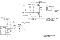
Here is the modified schematic (edited in none other than windows paint. Uzzors2k gets all credit for this schematic - its his work, sorry your copyright is missing mate - I used the left hand bit to do the copy/pasting!)
This should work correctly yes? I've spent a lot of time working out how a comparator works, and really I should know - I am an amateur radio operator after all - had to study this stuff to pass. Also renewed my knowledge of voltage dividers.
As far as I can tell the TL431 (which can be replaced by a LM336-2.5V, I hope), feeds the non inverting input, and when the voltage across either divider becomes greater than 2.5V, at the inverting pin, the comparator switches state, turning on the transistor and stopping charge.
Also I assume that switch is wired as normally closed, and pressing it / toggling it (the charge switch) allows the comparator to take over, charging the caps.
Otherwise the circuit would start charging unless the button is held down / switch is in the wrong position.
For substitution of parts due to what we have here at jaycar:
IRFP250: IRFP540
Bridge (on output) RGP10J : 4 x 1000v fast diodes
Indicator circuit: 100V panel meter (digital) with 1M + 100K resistor + 25k trimpot as voltage divider for the meter.
The trimpot will allow metering to be calibrated against a multimeter from 87V to 105V. So if I am looking at 430v on my meter, I want to adjust my panel meter to read 43.00 volts. (thus turning the 100volt meter into a 1kv one :P)
Any thought? have I made any errors here?
As an aside, I intend to use my bank for launching hard drive platters. I have 10 2400uf 450V capacitors to play with (and yes I know 2.43 kj is lethal, so have a smaller 330uf 450 v cap to experiment with until all my saftey precautions are in place!). Also some fun blowing up soft drink cans and bits of wire wouldn't go astray. Better get some ear defenders, leather gloves and some saftey glasses!
Cheers
Ben
Re: Bens foray into building a cap bank with uzzors charger
currentkills91, Fri Jun 17 2011, 10:49PM
I like what you've done, and it should work, but you don't really need the second trimmer. Just add the second resistor to the same pot, and switch between the resistors. :)
currentkills91, Fri Jun 17 2011, 10:49PM
I like what you've done, and it should work, but you don't really need the second trimmer. Just add the second resistor to the same pot, and switch between the resistors. :)
Re: Bens foray into building a cap bank with uzzors charger
vk2fro, Sat Jun 18 2011, 12:22AM
hey thanks for the reply - I thought "duh yeah dont need the second trimmer" then it dawned on me why its there -
We're charging caps, and if a marginal cap is in the bank ready to blow as soon as you go over 450V its better to have a trimmer per voltage range. The setting on the 950 v range may be different to the setting on the 450v range (My system will use logic and 2 big contactors to rearrange the cap bank from parrallel to series). I failed to mention that the range switch is part of a multipole relay, one of the sets changing the range on the charger, the other throwing the contactors.
I may need to include some logic to prevent this contact actioning unless the caps are discharged to a safe level). Or just a big sign on the control cabinet "DO NOT THROW RANGE SWITCH IN CHARGED STATE!" ;)
Am going to try and get some nice industrial saftey switches for the unit, and house the control panel in a seperate cabinet, so the operator can stand well back from exploding wires and flying hard drive platters. Will fit voltmeters to both bank and control box for saftey.
Re: Bens foray into building a cap bank with uzzors charger
currentkills91, Sat Jun 18 2011, 01:58AM
Hmm, sounds interesting :D How big you want the switches to be? I might be able to help on those :D
currentkills91, Sat Jun 18 2011, 01:58AM
Hmm, sounds interesting :D How big you want the switches to be? I might be able to help on those :D
Re: Bens foray into building a cap bank with uzzors charger
vk2fro, Sat Jun 18 2011, 09:27AM
This is a typical press switch

The press button depresses into the shroud around the button, preventing it being pressed accidentally (for example, by a dropped object, or someone leaning on the console). The ones I am after are backlit (and obviously dont need to carry anywhere near as much voltage or current - the contactors and relays will handle that).
vk2fro, Sat Jun 18 2011, 09:27AM
This is a typical press switch

The press button depresses into the shroud around the button, preventing it being pressed accidentally (for example, by a dropped object, or someone leaning on the console). The ones I am after are backlit (and obviously dont need to carry anywhere near as much voltage or current - the contactors and relays will handle that).
Re: Bens foray into building a cap bank with uzzors charger
currentkills91, Sun Jun 19 2011, 03:22AM
Well, I don't have anything like that. Radioshack sells some switches with covers over them - These - probably not what your looking for, but they would have the same concept really.
currentkills91, Sun Jun 19 2011, 03:22AM
Well, I don't have anything like that. Radioshack sells some switches with covers over them - These - probably not what your looking for, but they would have the same concept really.
Re: Bens foray into building a cap bank with uzzors charger
vk2fro, Mon Jun 20 2011, 02:48PM
yep - I have a missile switch for use as the pre firing switch - it'll disconnect the charging circuitry and enable the fire button / remote button.
vk2fro, Mon Jun 20 2011, 02:48PM
yep - I have a missile switch for use as the pre firing switch - it'll disconnect the charging circuitry and enable the fire button / remote button.
Re: Bens foray into building a cap bank with uzzors charger
vk2fro, Thu Jun 23 2011, 09:02AM
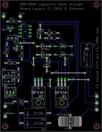
Well guys, what do you think of my little fiddle in Eagle cad?
I've designed up a board to accomodate a range of tank cap and inductor sizes, and has plenty of space for heatsinks on the mosfets (I got lazy too with compacting my components LOL).
I'd say keeping it like this gives a reasonable voltage standoff - hence I I didnt pack components in too tightly. Although the switch is located on board, I'd prefer to mount this and the 1 meg resistor off board.
Cheers
Ben

Re: Bens foray into building a cap bank with uzzors charger
currentkills91, Thu Jun 23 2011, 11:06AM
Looks like its coming along nicely :D
currentkills91, Thu Jun 23 2011, 11:06AM
Looks like its coming along nicely :D
Re: Bens foray into building a cap bank with uzzors charger
Forty, Thu Jun 23 2011, 04:16PM
very nice. i designed a board for just the zvs part, didn't even attempt the regulator bit. make sure you put in some beefy traces for the high current areas, wouldn't want to print that nice board and have parts of it melt. i agree that placing the 1M resistor off board is a good idea, that way you don't have any high voltage on your board. use insulating pads for the fet heatsinks too, i've noticed you can get shocked by touching the sinks if they're not insulated.
Re: Bens foray into building a cap bank with uzzors charger
vk2fro, Thu Jun 23 2011, 06:13PM
Version 2.0 - heavier traces, board slightly reorganised, and parts labelled properly (2 ic's and a transistor).
Comments? :)
Once you all think its looking good, I'll head over to the "hackers space" (a workshop a few suburbs over) and knock up a board :)
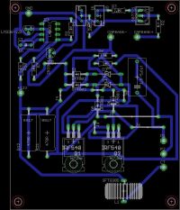
edit: BUM! forgot to rename the fast diodes - they ARENT 1N4004's - theyre FR307 1000V diodes. The two zener's are 5 watt jobs. Can you tell I overspec my parts?? ;)
vk2fro, Thu Jun 23 2011, 06:13PM
Version 2.0 - heavier traces, board slightly reorganised, and parts labelled properly (2 ic's and a transistor).
Comments? :)
Once you all think its looking good, I'll head over to the "hackers space" (a workshop a few suburbs over) and knock up a board :)

edit: BUM! forgot to rename the fast diodes - they ARENT 1N4004's - theyre FR307 1000V diodes. The two zener's are 5 watt jobs. Can you tell I overspec my parts?? ;)
Re: Bens foray into building a cap bank with uzzors charger
Forty, Thu Jun 23 2011, 07:00PM
as long as you've checked over the circuit a few times to make sure everything is correct, i'd say go for it.
Forty, Thu Jun 23 2011, 07:00PM
as long as you've checked over the circuit a few times to make sure everything is correct, i'd say go for it.
Re: Bens foray into building a cap bank with uzzors charger
vk2fro, Fri Jun 24 2011, 10:38PM
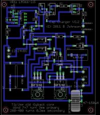
Heres version 2.2; now I have all my parts. The solder pads for Vin and the transformer fit the PCB headers perfectly on the 1:1 printout, along with all my diodes once I changed them to the correct device size.
Note most of the 45° angle turns have now gone, and the board has even SHRUNK by 1Cm :) The very busy section up near the comparator has also been made less busy, which should make for less chance of getting a solder bridge / bum board from the fab place.
I have created gerbers and have studied the circuit to make sure nothing has been miswired. I'm going to get itstore to make the boards ($25 bux for 10 is cheepo!)
Now just have to A) wait for bank balance to have money in it, and B) wait for my darn caps and IRF540's to turn up (bloody ebay!)
Cheers
Ben

Re: Bens foray into building a cap bank with uzzors charger
Forty, Sat Jun 25 2011, 12:15AM
get a few more posts (site rules) and you can likely sell some of your extra boards on here to make some money back.
Forty, Sat Jun 25 2011, 12:15AM
get a few more posts (site rules) and you can likely sell some of your extra boards on here to make some money back.
Re: Bens foray into building a cap bank with uzzors charger
vk2fro, Sat Jun 25 2011, 11:26AM
Good thinking - I can probably sell them as kits, with the PCB, major components, and leave the variable components (voltage divider resistors, resonance cap) up to the builder (as these components vary).
The majority of people will only want one voltage, but thats easily settled, omit one voltage divider resistor and replace the switch with a wire link.
I have just added metering - the cheap LED 200V DC meters on ebay will do the trick- even stuffed an LM7805 on board to power it :) By changing the sense resistor on the board, a variety of voltages can be obtained from the Meter In pad on the pcb. Right now I have a 0-200v meter on the way, so I set the resistor to divide input voltage by 10. This will give a reading of 90 volts at 900volts across the bank. First thing I will do is snip the anode lead of the decimal point on the meter ;) They have a ground that is common with the input (measured) voltage, so only need 3 connections.
I considered powering the meter from the cap bank charge, but at 900 volts, the zener would be small, but the pass resistor would be a huge 50watt job. It would have been nice though, the meter would display voltage in the bank, even with the power off, as such, doubling as a "bank has charge" indicator.
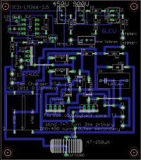
This thing is probably going to go through a few revisions before its time to have the boards made - major changes to 3.0 include fixing the mosfets vertically, addition of metering output. Also pad spacing between I/O's allows for the use of the nice PCB mount screw terminal connectors jaycar sells (they appear to fit nice on the 1:1 printout anyway :P)
Heres version 3.0.

Re: Bens foray into building a cap bank with uzzors charger
Forty, Sat Jun 25 2011, 05:21PM
you can get those terminal connectors on bgmicro for a lot cheaper. although i don't know about shipping costs to australia.
Forty, Sat Jun 25 2011, 05:21PM
you can get those terminal connectors on bgmicro for a lot cheaper. although i don't know about shipping costs to australia.
Re: Bens foray into building a cap bank with uzzors charger
vk2fro, Sat Jun 25 2011, 06:10PM
hehe too late - already got em - and yeah shipping - probably get them 3 weeks later - got mine from jaycar in one day. :)
vk2fro, Sat Jun 25 2011, 06:10PM
hehe too late - already got em - and yeah shipping - probably get them 3 weeks later - got mine from jaycar in one day. :)
Re: Bens foray into building a cap bank with uzzors charger
vk2fro, Mon Jun 27 2011, 06:32AM
Drat - cant add an attachment to my previous post or I would have edited it instead of double posting.
Look what turned up today
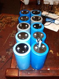
Sitting on top in the forground is a PC psu cap - these things are huge. Each is rated at 2.4mF 450b (525 surge), which nets me a bank of 24mF at 450V or 12mF at 900V :)
I will start by adding a rotary switch to my charger, and setting it up for 80,160,320 and 450, and reform these before banking them up - will do them one at a time. For lower voltages (12 v) I have 4 7ah gel batteries. I'll just tack one on after the other in series to get to ~ 50 v
of course when I can afford it I'll be buying another 30 caps, along with an ESR meter so I can check them all, and arrange them in two parrallel strings of 20, for a whopping total of 10kJ ish :)
vk2fro, Mon Jun 27 2011, 06:32AM
Drat - cant add an attachment to my previous post or I would have edited it instead of double posting.
Look what turned up today

Sitting on top in the forground is a PC psu cap - these things are huge. Each is rated at 2.4mF 450b (525 surge), which nets me a bank of 24mF at 450V or 12mF at 900V :)
I will start by adding a rotary switch to my charger, and setting it up for 80,160,320 and 450, and reform these before banking them up - will do them one at a time. For lower voltages (12 v) I have 4 7ah gel batteries. I'll just tack one on after the other in series to get to ~ 50 v
of course when I can afford it I'll be buying another 30 caps, along with an ESR meter so I can check them all, and arrange them in two parrallel strings of 20, for a whopping total of 10kJ ish :)
Re: Bens foray into building a cap bank with uzzors charger
vk2fro, Thu Jul 14 2011, 05:21AM
Since I cant attach another pic to my previous post, I apologise for triple posting.
Heres my final revision of the cap charger board in the flesh!
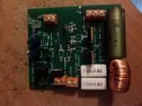
Observant viewers will notice the fast diodes are missing. They're too big for the boards holes. Since I dont have a 0.8mm mini drill, I will need to wait until I get one to finish adding the diodes.
As I STILL havent found a busted TV to rip the flyback out of, testing cant go ahead at the moment anyway.
If all works well, I might offer the other 7 boards (I'm keeping 3) as a kit with all components included in the buy sell section, provided my post count is high enough as mentioned earlier. You just need to supply the flyback transformer and a 12V power source.
vk2fro, Thu Jul 14 2011, 05:21AM
Since I cant attach another pic to my previous post, I apologise for triple posting.
Heres my final revision of the cap charger board in the flesh!

Observant viewers will notice the fast diodes are missing. They're too big for the boards holes. Since I dont have a 0.8mm mini drill, I will need to wait until I get one to finish adding the diodes.
As I STILL havent found a busted TV to rip the flyback out of, testing cant go ahead at the moment anyway.
If all works well, I might offer the other 7 boards (I'm keeping 3) as a kit with all components included in the buy sell section, provided my post count is high enough as mentioned earlier. You just need to supply the flyback transformer and a 12V power source.
Re: Bens foray into building a cap bank with uzzors charger
Forty, Fri Jul 15 2011, 01:17AM
looks very nice.
I can't believe you could design and make that, but don't have an extra flyback transformer, lol.
I don't think it technically has to be a flyback core, any ferrite core should do, given that you can fit your windings in it.
Forty, Fri Jul 15 2011, 01:17AM
looks very nice.
I can't believe you could design and make that, but don't have an extra flyback transformer, lol.
I don't think it technically has to be a flyback core, any ferrite core should do, given that you can fit your windings in it.
Re: Bens foray into building a cap bank with uzzors charger
vk2fro, Fri Jul 15 2011, 02:37AM
I'm surprised too - usually I have 1 or two flyback transformers hanging around. I will have a couple of transformers next week so all is good (some busted TV's to rip into)
edit:
I'm still working on this folks. I have 2 TVs now to gut the EHT transformers out of, for their cores, just waiting on some other components to arrive.
I have selected a 200 watt 10K ohm discharge resistor. Now just need to find a nice big contactor to switch it in when the switch on the control box is dialed to "dump" :)
The resistor should dump the bank in 5 minutes. A circuit will keep power from the 12V source to the led meter until the bank is below 12V, so its basically "while that meter is lit, stay away" :)
Edit:
A week or so later and television number one has been delivered, and has had its mainboard stripped from it. Amoungst other nice parts, I have one intact flyback. A second TV will be on its way in a few days. First edit was meant to mention "I have 2 TV's to gut being delivered by friends". One has turned up :)
All thats left to do with the telly is neck the tube and toss it into the bin.
Waiting for: Copper, SCR Clamp (on its way), plexi box, and a bigger control console box :P
Re: Bens foray into building a cap bank with uzzors charger
vk2fro, Sat Oct 01 2011, 06:56AM
Well folks, progress!
I've found a local company who can make up my bus bars. I've also found a silicon chip article that entails a cap reformer circuit which is intelligent (uses a pic micro) and probably a good idea as I dont know the history of my caps, and dont want one to go boom near me.
I'll put the cap reformer kit inside a large plastic toolbox, which will also house the cap under test, and sit it outside. Since it runs off 12v, I'll pop a car battery nearby to power it.
My SCR has arrived, along with its clamp and a shedload of other bits and pieces.
I still need to order my bus bars, wind my transformer (I got the core out of a flyback today using a pair of needlenose pliers to remove the clip, and zippo cigarette lighter fluid to dissolve the glue. A AAA battery makes a great plunger to push the core out of the FBT :) I have some 3M acetate overhead projctor transparancy to use as insulation between the secondary windings. (conveniently pinched by a friend from his work LOL)
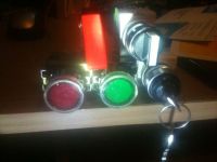
I also got some nice switches for the control panel, and a nice sloping panel box for the control cabinet that has one little problem! TOO SMALL *doh!* It'll get used for another project though, so I have to go back to RS components and order its bigger brother. (the box is not deep enough for my switches). I also got a 200 watt (!) 10K aluminium clad resistor. Its as big as a sausage roll! It will be my "dump" resistor should I choose not to fire the bank.
TO DO:
1. Order a freewheeling diode of ebay (big bugger)
2. Finish adding the components to the PCB (on their way from ebay)
3. Wind the transformer, replace globes in press buttons with LEDs
4. Build the control console
5. Build the SC cap reformer and reform my caps
6. Build cap bank box, order bus bar, attach caps to bar
7. Reform 11 more caps and add them to the bank.
7 will come later when I have spare funds to buy the extra caps. They will bring the bank total power to 5kj, which should be MORE than enough for a home version of the geek groups "Thumper" :)

Re: Bens foray into building a cap bank with uzzors charger
Forty, Sun Oct 02 2011, 10:34PM
I haven't looked around on ebay yet for diodes, so i'm not sure if this will help, but I did find this:

Forty, Sun Oct 02 2011, 10:34PM
I haven't looked around on ebay yet for diodes, so i'm not sure if this will help, but I did find this:

Re: Bens foray into building a cap bank with uzzors charger
vk2fro, Tue Oct 11 2011, 05:12AM
Thanks forty - that looks the business and cheaper than stuff I've seen on ebay (I dont really need a puck diode).
Might order 2 of them. My fast diodes turned up so I have fitted them to the PCB. All I am waiting on now is the 110K resistors (got 3000 assorted resistors from ebay) and a 5K trimpot.
The circuit will function without them, they are only the meter output, but I'd rather have the board finished ready for installation.
I also need to find a vibratory horn (for the firing alarm)
I also need to get off me bum and wind the step up transformer :)
Re: Bens foray into building a cap bank with uzzors charger
vk2fro, Fri Oct 21 2011, 02:18AM
Hi guys
Further updates. I've ordered copper bus bar for my caps, along with a larger sloping panel box so I can get the control panel built.
I need some suggestion for the IO socket. It will carry low current (tops 300ma) at 12V to power relays in the cap bank box, for charging, bleeding, firing, and disconnection of the charger from the bank. I assume an 8 pin din will be suitable for this task? The incoming 12V will be fused with a 1A fuse, the max the control box will draw is 600ma, thats with the three illuminated switches lit, and the display, along with the trigger handpiece button (spectator control) lit. This is an impossible situation, as the charge light will immediatly go out once the selector switch is moved from charge to fire. Likewise, the remote and bleed/fire lights go out when the selector switch is moved to "charge".
So is an 8pin din suitable for this purpose. The bank will have its own inbuilt SLA batteries, and a key that needs to be inserted to power the box. (a shorted 30A pair of andersons).
Without the control box connected, the bank box will be in a state of no charge, no fire, bleed resistor connected. This is with or without the "arming" anderson key inserted.
As well, a 4 pin (as found on CB radios) microphone socket and plug will interconnect the trigger remote to the control box, and a bnc will connect the up to 90VDC (10:1) from the voltage divider on the bank to the display board.
The only thing going back to the control box that is over 50v is the low current feedback voltage off the voltage divider, everything else is 12V or below. (5v for the display board etc).
Any suggestions of easily obtainable connectors in australia would be appreciated.
Oh, and I wound my transformer secondary onto a nice little former, and then test fitted the ferrite and clips, and sat there with a satisfied grin, only to notice that there was NO room on it for a primary :P God i was so pi$$ed! I'll be sticking with the flyback core :)
Re: Bens foray into building a cap bank with uzzors charger
vk2fro, Tue Nov 15 2011, 08:26AM
Bus bars look good - solid copper (and cost a small fortune LOL)
Now need a drill press and can get started making the bank proper :)

edit:
found a simplex 4040/vibratone 350 horn on ebay!! now I have a similar alarm to TGG, but this ones 24V ac, so I can drive it with a baby inverter and a transformer (they're cheaper than making a dedicated 24V AC inverter for 12V)
edit 2: looks like I made an error. The horn has arrived. Its 24VDC, so thats easy as I already have a 12-24Vdc converter that has enough current to run it.
I built a timer module to blast the horn at one second bursts. So I just hold down the alarm button and it will automatically do its thing. I finished the inverter (yep transformer finally wound) and fixed an error on the pcb (Which was fatal when the first one got plugged up to 12v), so have ordered a new set of PCB's. These have the bonus of the transformer being onboard, and the hv bridge. They only have one range though - 900V. I've decided not to go with bus bar shifters to make the system dual range (i.e. switch fom series to parallel for 450v and vice versa for 900V). The circuit will however, be adjustable from 50v to 1200 volts, so should be suited to anyone who wants to build one. (will sell them as kits once I've tested them). The hysterisis on the lm 393 has been improved with a 555 timer and relay (for user isolation). Once a charged state is reached, the charger portion is disabled for 5 seconds, to prevent the board oscillating as the voltage rises above and drops below the target voltage. The transformer is based on a philips FX2440 core which will mount right on the board.
Trigger board for the big scr is also on its way as well. You feed it 12V, and to fire, you short 2 pins. Its a seperate board so it can be mounted close to the firing SCR, and thus reduce the chance of false triggering by noise from the inverter board.
vk2fro, Tue Nov 15 2011, 08:26AM
Bus bars look good - solid copper (and cost a small fortune LOL)
Now need a drill press and can get started making the bank proper :)

edit:
found a simplex 4040/vibratone 350 horn on ebay!! now I have a similar alarm to TGG, but this ones 24V ac, so I can drive it with a baby inverter and a transformer (they're cheaper than making a dedicated 24V AC inverter for 12V)
edit 2: looks like I made an error. The horn has arrived. Its 24VDC, so thats easy as I already have a 12-24Vdc converter that has enough current to run it.
I built a timer module to blast the horn at one second bursts. So I just hold down the alarm button and it will automatically do its thing. I finished the inverter (yep transformer finally wound) and fixed an error on the pcb (Which was fatal when the first one got plugged up to 12v), so have ordered a new set of PCB's. These have the bonus of the transformer being onboard, and the hv bridge. They only have one range though - 900V. I've decided not to go with bus bar shifters to make the system dual range (i.e. switch fom series to parallel for 450v and vice versa for 900V). The circuit will however, be adjustable from 50v to 1200 volts, so should be suited to anyone who wants to build one. (will sell them as kits once I've tested them). The hysterisis on the lm 393 has been improved with a 555 timer and relay (for user isolation). Once a charged state is reached, the charger portion is disabled for 5 seconds, to prevent the board oscillating as the voltage rises above and drops below the target voltage. The transformer is based on a philips FX2440 core which will mount right on the board.
Trigger board for the big scr is also on its way as well. You feed it 12V, and to fire, you short 2 pins. Its a seperate board so it can be mounted close to the firing SCR, and thus reduce the chance of false triggering by noise from the inverter board.
Re: Bens foray into building a cap bank with uzzors charger
vk2fro, Mon Nov 26 2012, 08:44PM
Hi folks - this project has been on hold up until now - and now I am having SCR issues.
Each module that I build I test to ensure I dont blow up expensive components (like my hockey puck SCR). I built the SCR trigger circuit on this page:
http://www.powerlabs.org/pssecc.htm
and replaced the trigger switch with a relay so an AVR can trigger it. When I measured the voltage across the gate output (which would normally connect to the gate of the big SCR) and ground, I'm seeing 0V when powered on, and a few millivolts (e.g. 7.6mV) when I fire the relay. Shouldn't I be seeing a few volts here?
Print this page