
ARC STARTER AND STABILIZER - COMPLETED
Newton Brawn, Fri Apr 01 2011, 10:00PMHi !
Here the complete arc starter to be attached to a buzzbox, tig, or a plasma cutter.
Description:
]arc_starter_original_complete_w-rev2_in_pdf.pdf[/ file]
Drawings:
]des_arc_starter_and_stabilizer_r2.pdf[/file]
]des_sssg_schematics_r2.pdf[/file]
]des_tungsten_carbide_spark_gap_r3.pdf[/file]
]des_pulse_transformer__coupling_coil_r2.pdf[/ file]
]des_hv_glass_capacitor__r2.pdf[/file]
Pictures:
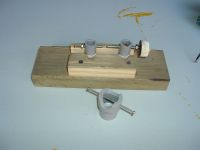
Parafernalia to measure the HV pulses and spark gap used in begin of project.
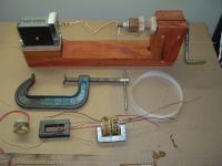
Device to wind the pulse transformer - a turn counter and cranckcase. Also a C clamp to hold the device in the table, polyester paper to insulate the layers of the coil, a ferrite core from a tv, a coil after the impregnation.
[/img]]
There are more pictures and a video.
Regards
Newton
Re: ARC STARTER AND STABILIZER - COMPLETED
Ash Small, Sat Apr 02 2011, 06:02AM
Very nice work Newton. Do you have any photos of the complete unit?
I'm making some new heatsinks to upgrade my rectifier at the moment and I hope to get my HF arcstarter down here soon (it's in storage 200 miles away at the moment, along with my buzzbox).
Once I've done that I'll post some details of mine, which is simpler, but runs continuously.
Re: ARC STARTER AND STABILIZER - COMPLETED
Newton Brawn, Sun Apr 03 2011, 11:49PM
Hi Ash Small !
SIm, I have several pictures showing the device under test. It is a assemble not 100% beatiful, but just to put the components together and allow changes in te schematic.
I have a short video, "15+kV in the hands", however I could not attache to the forum. Maybe I can send direct to you
I have tested other circuits simpler tham this one, let me know the schematic of your arc starter.
Regard
Newton
Pictures:
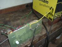
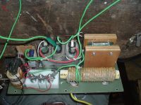
Arc Starter Under Test
Back Picture
Tungsten Carbide Spark Gap


Re: ARC STARTER AND STABILIZER - COMPLETED
Ash Small, Mon Apr 04 2011, 03:01PM
I'll try to draw a circuit from memory later (it's ten years since built it).
In the meantime I'll upload an animated GIF that I created from a basic 3D model I drew when designing a case for it.
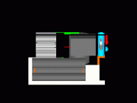
(EDIT: Looks like you need to 'click' on the above image to see the animation)
The case is about 12"X12"X18".
I'll start by decribing the layout of components on the front panel.
First, there are the two input and two output glands for the welding current, along with 240V in and argon in/out.
There is the argon flowmeter/controller in the centre, on/off switch on the upper right, and a 'power on' indicator and coloured lens through which I can see the sparkgap, for positive conformation that it is functioning. (the sparkgap is an unsuppressed automotive spark plug).
The three long cylindrical components on the left hand side at the bottom are the hand-rolled HV capacitors. Two of these form part of the HF choke (low pass filter), the other forms part of the spark tank circuit.
Above these are, at the rear, the heatsink cooled by two computer case fans (one blowing, one sucking) which houses the 2N3055 transistor that switches the flyback transformer. (There is a cutout in the back panel for cooling, along with louvres in the sides of the case).
The rest of the switching circuit (two resistors) is housed in front of the heatsink, above the HV capacitors. (along with the flyback transformer, with a ten turn primary and four turn feedback winding)
The box-shaped item at the right lower rear is the 12V wall-wart that privides power to the switching circuit for the flyback, and also powers the cooling fans on the transistor heatsink..
In front of this, (lower right centre) is the choke, which, along with two of the HV capacitors, stops the HF getting back into the rectifier and buzzbox. (The choke is wound on a 50Hz toroidal transformer core)
The component at the left front is the air cored transformer that superimposes the HF onto the welding current. This is arranged in a different orientation to the choke in order to minimize any interference between these two components.
I'll try to provide a circuit diagram and more details later.
(work in progress......)
Ash Small, Mon Apr 04 2011, 03:01PM
I'll try to draw a circuit from memory later (it's ten years since built it).
In the meantime I'll upload an animated GIF that I created from a basic 3D model I drew when designing a case for it.

(EDIT: Looks like you need to 'click' on the above image to see the animation)
The case is about 12"X12"X18".
I'll start by decribing the layout of components on the front panel.
First, there are the two input and two output glands for the welding current, along with 240V in and argon in/out.
There is the argon flowmeter/controller in the centre, on/off switch on the upper right, and a 'power on' indicator and coloured lens through which I can see the sparkgap, for positive conformation that it is functioning. (the sparkgap is an unsuppressed automotive spark plug).
The three long cylindrical components on the left hand side at the bottom are the hand-rolled HV capacitors. Two of these form part of the HF choke (low pass filter), the other forms part of the spark tank circuit.
Above these are, at the rear, the heatsink cooled by two computer case fans (one blowing, one sucking) which houses the 2N3055 transistor that switches the flyback transformer. (There is a cutout in the back panel for cooling, along with louvres in the sides of the case).
The rest of the switching circuit (two resistors) is housed in front of the heatsink, above the HV capacitors. (along with the flyback transformer, with a ten turn primary and four turn feedback winding)
The box-shaped item at the right lower rear is the 12V wall-wart that privides power to the switching circuit for the flyback, and also powers the cooling fans on the transistor heatsink..
In front of this, (lower right centre) is the choke, which, along with two of the HV capacitors, stops the HF getting back into the rectifier and buzzbox. (The choke is wound on a 50Hz toroidal transformer core)
The component at the left front is the air cored transformer that superimposes the HF onto the welding current. This is arranged in a different orientation to the choke in order to minimize any interference between these two components.
I'll try to provide a circuit diagram and more details later.
(work in progress......)
Re: ARC STARTER AND STABILIZER - COMPLETED
Newton Brawn, Mon Apr 04 2011, 04:50PM
Hi All
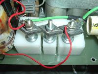
It appears that we can not open the last picture , so I m attaching again.
Regards
Newton Brawn, Mon Apr 04 2011, 04:50PM
Hi All
It appears that we can not open the last picture , so I m attaching again.
Regards

Re: ARC STARTER AND STABILIZER - COMPLETED
Newton Brawn, Sat Apr 09 2011, 08:54PM
Ash Small ,
What bring my attention is yours hand made capacitors....Can you provide a good description of its construction ???
Please let me know the schematic of your arc stater, I am really interested on it.
Regards
EDIT: Change of contraction to construction
Re: ARC STARTER AND STABILIZER - COMPLETED
Ash Small, Sun Apr 10 2011, 02:30AM
I'm planning to make some more capacitors this week, so I'll write it up and provide some photos.
Ash Small, Sun Apr 10 2011, 02:30AM
I'm planning to make some more capacitors this week, so I'll write it up and provide some photos.
Re: ARC STARTER AND STABILIZER - COMPLETED
Ash Small, Sun Apr 10 2011, 04:45PM
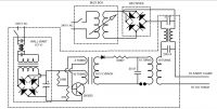
The World's Simplest HF DC TIG welder (schematic).
I built this ten years ago, but I'm pretty certain it is accurate.
(not sure if the second capacitor (50 nano) on the HF choke is required, or if the 'mains protection choke' on the wall wart is required, I added them as a precaution, so, in theory, it could be even simpler.
I've not tried other values for capacitors, or number of turns on air core transformer, as it worked OK first time I tried it (if it ain't broke, don't fix it), but knowing what I know now, I'd probably try some different values. I think the value of the resistor was 330 K Ohms (it was 330 something, I think)
I also might add some protection for the 2N3055 transistor. (I forgot to add the two PC fans cooling the transistor heatsink)

Re: ARC STARTER AND STABILIZER - COMPLETED
Newton Brawn, Wed Apr 13 2011, 02:24PM
Ash;
Following the World's Simplest HF DC TIG welder (schematic as previous thread ):
I am also not shure about the real need of the iron core bifilar choke on the output of the rectifier ON PREVENTING THE HV molesting the rectifiers.
Following the schema you can see that the HF from the coupling coil can reach very easy the rectifiers and the secondary of welder transformer. This is because the choque capacitance between turns and other stray components.
A capacitor 0.2 ~~ 2uF from the + of the rectifier to ground and other cap of same value from - of rectifier to ground will reduce the HV HF to very low magnitude, avoiding the HF bad effects on rectifies and buzzbox components.
Miller HF15, HF251 and several other machines do not use bifilar choke. Just caps to block the HF.
Note that in the previous thread schema the bifilar choque shall be coiled with wire size suitable for high current.
Also a DC choke just after the rectifier bridge is fine to smooth the rectifier 120Hz pulsing current, giving some help stabilizing the arc.
The values 330Kohms and 0.02uF cap look ok. One discharge evey 5 ~~10 milesecond, controled by the adjustment of gap distance of spark gap. The result is HF pulses not synchronized with the pulsing dc output of the buzzbox... Some misfire during the stabilizing process.
Next time, I wiil show a simpler arc starter ckt
Regards
Newton
Re: ARC STARTER AND STABILIZER - COMPLETED
Ash Small, Wed Apr 13 2011, 02:43PM
I think the frequency is higher than 5-10 milliseconds. The resistor plays no part in determining frequency, it simply blocks the current circulating in the tank from getting back to the secondary of the flyback. (it follows the path of least resistance).
Frequency is determined by the 20 nano farad capacitor and inductance of the primary of the air core transformer, which I wasn't able to measure when I built it (ten turns 25 mm diameter by ~120 long).
At least, this was the theory I used when I designed it.
Ash Small, Wed Apr 13 2011, 02:43PM
Newton Brawn wrote ...
.
The values 330Kohms and 0.02uF cap look ok. One discharge evey 5 ~~10 milesecond, controled by the adjustment of gap distance of spark gap. The result is HF pulses not synchronized with the pulsing dc output of the buzzbox... Some misfire during the stabilizing process.
.
.
The values 330Kohms and 0.02uF cap look ok. One discharge evey 5 ~~10 milesecond, controled by the adjustment of gap distance of spark gap. The result is HF pulses not synchronized with the pulsing dc output of the buzzbox... Some misfire during the stabilizing process.
.
I think the frequency is higher than 5-10 milliseconds. The resistor plays no part in determining frequency, it simply blocks the current circulating in the tank from getting back to the secondary of the flyback. (it follows the path of least resistance).
Frequency is determined by the 20 nano farad capacitor and inductance of the primary of the air core transformer, which I wasn't able to measure when I built it (ten turns 25 mm diameter by ~120 long).
At least, this was the theory I used when I designed it.
Re: ARC STARTER AND STABILIZER - COMPLETED
Newton Brawn, Thu Apr 14 2011, 12:44AM
Yes, I agree that the pulse frequency is higher, in the range of megahertz. The discharge of the cap through the coil produce a momentary oscillation that finishes as soon the cap is discharged.
More precise:
Coil inductance = N^2 n D^2 / (18D + 40D) =
= 10^2 x 1^2 /( 18 x 1 + 40 x 4.7) = 0.49uH
Pulse frequency = 1/(2 x pi x (L xC)^1/2 =
= 1/ (2 x pi x(0.49 x 0.02)^1/2 = 1.6mHz
This pulse is the result of fast discharge of the cap through the air gap and primary air core coil.
As soon the cap is discharged, the oscillation stop and the rectifier and the 330kohm resistor starting to charge the cap. This charging takes time.
The time required to charge the cap to 63% of its full voltage is dictaded by the RC constant, this case 6.6miliseconds.
I considered the transistor circuit strong enough to charge the cap easilly.
Since a good practice is set the gap 50~~70 % of cap full voltage, the repetition of each oscilation is in the range of 5 ~~10 ms.
All above are a theorectical manipulation. Small deviations may occurs.
Regards
EDIT: please note that the above calculation applies only to the TRANSISTORIZED circuit posted by Ash Small on april 10.
Re: ARC STARTER AND STABILIZER - COMPLETED
Newton Brawn, Fri Jul 22 2011, 04:55PM
Hi !
Please see the EDIT note posted by Newton doing clarifications on the last post.
Regards
Newton Brawn, Fri Jul 22 2011, 04:55PM
Hi !
Please see the EDIT note posted by Newton doing clarifications on the last post.
Regards
Re: ARC STARTER AND STABILIZER - COMPLETED
Ash Small, Fri Jul 22 2011, 05:10PM
I've recently been reading about the 'loose coupling' that transfers energy from the primary to the secondary. Is it possible to work out how many oscillations it would take to transfer all the energy from each charging of the capacitor to the secondary.
I appreciate that the secondary circuit isn't tuned to the primary, so any advice regarding this would also be appreciated.
(I have now got the HV TIG welder here, I'm just building a new rectifier before I start using it/modifying it again.)
Re: ARC STARTER AND STABILIZER - COMPLETED
Newton Brawn, Thu Nov 17 2011, 03:24AM
Hi !
Just to reply some emails regarding the spark gap construction.
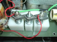
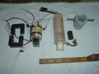
See attached picture of the parts used in the Arc Starter
At right you can see the spark gap using a pvc pipe and 2 mild steel bolts. This spark gap was used in the begining of the development of the circuit, it works very well. It should be noted that the energy dissipated is very low, due to only two syncronized pulses in each period of 60Hz. No temperature rise was noted.
Any questions, let me know .
Regards
Newton
Newton Brawn, Thu Nov 17 2011, 03:24AM
Hi !
Just to reply some emails regarding the spark gap construction.
See attached picture of the parts used in the Arc Starter
At right you can see the spark gap using a pvc pipe and 2 mild steel bolts. This spark gap was used in the begining of the development of the circuit, it works very well. It should be noted that the energy dissipated is very low, due to only two syncronized pulses in each period of 60Hz. No temperature rise was noted.

Any questions, let me know .
Regards
Newton
Re: ARC STARTER AND STABILIZER - COMPLETED
Rick, Sat Dec 24 2011, 08:59AM
Newton:
I hope you'll entertain a question from one who isn't highly knowlegeable about electronics. I'm trying to duplicate your arc starter circuit and have built the components per your descriptions. I'm now trying to make the sssg but am confused by the two wiring diagrams. The sssg diagram shows the aircore coil as part of the sssg, but the diagram of the whole circuit shows it between the RL and CD. Could you please clarify this for me? Also, is the RL resistor the one shown in the sssg diagram mounted on an angle going into the pot? Thank you.
Rick A
Re: ARC STARTER AND STABILIZER - COMPLETED
Newton Brawn, Tue Dec 27 2011, 08:47PM
Hi Rick A !
Thanks for your review and comments !
You are 1000 % correct.
My mistake is re " consistence of information" .
If L1 is appearing in the drawing des_arc_starter_and_stabilizer_r2.pdf
it shall not appear in the drawing des_sssg_schematics_r2.pdf.
The duplication of information allways generate confusion.
The L1 function is limit the di/dt during of discharging of CD to avoid damage in the SCR. L1 is not critical, 5 to 12uH is ok. The important is to be in series with CD and SCR anode.
In assembling or in electrical wiring, you can assembly L1 following the first drawing or as shown in the second drawing. ( or even adding TWO air core inductors, one L1 following the first dwg, and a second air core inductor as shown in the second draring ! - the circuit will work fine.)
You wrote:
Not really, the air core inductor is shown in both drawings in serie with CL, CD, LP,and SSSG. So, the L1 functin off limiting SCR di/dt is enforced.
Let me know more doubts, I will be happy in provide answers
Regards
Newton
Newton Brawn, Tue Dec 27 2011, 08:47PM
Hi Rick A !
Thanks for your review and comments !
You are 1000 % correct.
My mistake is re " consistence of information" .
If L1 is appearing in the drawing des_arc_starter_and_stabilizer_r2.pdf
it shall not appear in the drawing des_sssg_schematics_r2.pdf.
The duplication of information allways generate confusion.
The L1 function is limit the di/dt during of discharging of CD to avoid damage in the SCR. L1 is not critical, 5 to 12uH is ok. The important is to be in series with CD and SCR anode.
In assembling or in electrical wiring, you can assembly L1 following the first drawing or as shown in the second drawing. ( or even adding TWO air core inductors, one L1 following the first dwg, and a second air core inductor as shown in the second draring ! - the circuit will work fine.)
You wrote:
The sssg diagram shows the aircore coil as part of the sssg, but the diagram of the whole circuit shows it between the RL and CD.
Not really, the air core inductor is shown in both drawings in serie with CL, CD, LP,and SSSG. So, the L1 functin off limiting SCR di/dt is enforced.
Also, is the RL resistor the one shown in the sssg diagram mounted on an angle going into the pot?As shown in the drawings the position of RL is correct. RL mission is to limit the CL inrush current when you connect the circuit in the 230V line.
Let me know more doubts, I will be happy in provide answers
Regards
Newton
Re: ARC STARTER AND STABILIZER - COMPLETED
Rick, Fri Dec 30 2011, 07:23AM
Newton:
Thank you for the clarification. I'm just afraid to wire things up wrong and fry some of the components.
I'm also wondering if this circuit will work OK on 120 volts. As I understand it, your 220v is a 220v live wire and a neutral, whereas ours in the US is two 120v live wires 180* out of phase and a neutral, so I can only get a true 220v by running my 120 through a step-up transformer. We'll see!
Rick A.
Re: ARC STARTER AND STABILIZER - COMPLETED
Newton Brawn, Thu Jan 12 2012, 12:56AM
Hi Rick A.
Do not worry !
SINGLE PHASE SUPPLY SITUATION:
(The power outlet in your shop is 120 or 220~240V, or 125-0-125V, 220V at the lines, 50~60 Hz)
Since the arc starter is connected in the same power line of the buzzbox, the arc starter spark will be sinchronyzed with the buzzbox. Also the arc starter spark will be delayed of 25=35 degreees, provinding the proper ignition of the main arc.
As published the circuit works fine in 120V, Try it . If the spark at the gaps are less than 2.00mm you may increase the pulse energy:
1- the capacitor CD could be 0.94 uF (two 0.47 in parallel ) or one 0.94 x 2000V from a microwave oven.
2- the primary coil of T1, may have a tap at the 18th turn. for better voltage ratio.
Let me know the progress of the construction, send pics of your machine!
Regards
Newton
Re: ARC STARTER AND STABILIZER - COMPLETED
Redstone, Thu Jan 26 2012, 04:01PM
proper ignition? why would it matter? maybe if your running under current and have to keep it starting. but other wise who cares. misfires will work right?
Redstone, Thu Jan 26 2012, 04:01PM
proper ignition? why would it matter? maybe if your running under current and have to keep it starting. but other wise who cares. misfires will work right?
Re: ARC STARTER AND STABILIZER - COMPLETED
Newton Brawn, Sat Jan 28 2012, 01:36AM
D Rosey:
The concept of the apparatus:
1 - The buzzbox is a 50~75Vac transformer with high serial reactance in order to control the welding current. The buzzbox provides 60Hz main power to the welding arc. Under some conditions (very low welding current, operator"s hability) the welding arc stinguish, interrupting the welding process. Also, as the buzzbox supplies AC current that cross zero current at 120 times per second, the welding arc also may be interrupted 120 times per minute.
2- When the arc starter is coupled with the buzzbox, the arc starter provides 120 pulses per second superimposed upon the buzzbox supply. These pulses are enough to start the ignition of the main arc after each zero current pass. This assure the main arc stays alive producing heath for the welding.
The pulses provided by the arc starter are 10-15kV, 1-2 microseconds, VERY LOW energy 0.005J, in such way that you may touch the welding electrode without fill the electric shock.
A more detailed information you may read at US Patent # 2880376.
Any concern, let me know.
Regards
Newton

Re: ARC STARTER AND STABILIZER - COMPLETED
Tony Matt, Fri Jun 29 2012, 09:29PM
Hi Newton!
Do you have measured the capacitance of the window glass HV capacitors?
Any idea about the glass dielectric constant ?
Cheers
Tony Matt, Fri Jun 29 2012, 09:29PM
Hi Newton!
Do you have measured the capacitance of the window glass HV capacitors?
Any idea about the glass dielectric constant ?
Cheers
Re: ARC STARTER AND STABILIZER - COMPLETED
Newton Brawn, Sun Jul 01 2012, 09:30PM
Hi Tony!
Yes, the capacitor capacitance was measured before energization and also measured some time after the capacitor be running in pulse work.
I have found no changes in the capacitance. The window glass capacitor capacitance is stable, even when working long time with pulses.
The window glass (the cheapest flat glass) that I have used in Canada and Brazil has a dielectric constant of 8.9 to 9.2.
The electrodes are made of 0.015~0.02 mm aluminun foil that my wife use in the kitchen ... I have built some caps with thicker electrode and the result was not good, some corona inside the dielectric.
The leads are aluminun foil used in construction for roof flashing, 0.2mm thicker.
Let me know any info about your glass capacitor .
Regards
Re: ARC STARTER AND STABILIZER - COMPLETED
Tony Matt, Thu Mar 09 2017, 02:55AM
Hi Newton,
The circuit looks as 2 tesla circuits connected in series .
Is it possible?
Cheers
Tony Matt, Thu Mar 09 2017, 02:55AM
Hi Newton,
The circuit looks as 2 tesla circuits connected in series .
Is it possible?
Cheers
Re: ARC STARTER AND STABILIZER - COMPLETED
Newton Brawn, Fri Mar 10 2017, 11:51PM
Tony,
Yes, there are 2 tesla circuits in the schematic.
The first tesla is compound by CD, SSSG and T1. We may say that SSSG is sparkgap. The voltage line (220V) discharge through SSSG (triac) providing a pulse through CD and the primary of T1.
The second tesla is done by CT, GAP and TT.
The secondary of T1 charges CT then the GAP discharge CT through the primary of TT. The pulse resulted by this discharged is increased by TT providing 15kV to the its secondary. As the secondary of TT is in series with the buzzbox and torch, the welding electrode drives a spark to the welding work.
It should be noted that in a period of 16 milliseconds ( one 60Hz period ) the circuit provides 2 or 4 pulses. The pulses are synchronized with the torch ac voltage.
Regards
Re: ARC STARTER AND STABILIZER - COMPLETED
Newton Brawn, Wed May 15 2019, 08:31PM
Hi all members
please let me know how i can get all drawings listed in the article "arc starter and stabilizer .." by Newton Brwwn
regards
Newton.
Newton Brawn, Wed May 15 2019, 08:31PM
Hi all members
please let me know how i can get all drawings listed in the article "arc starter and stabilizer .." by Newton Brwwn
regards
Newton.
Print this page