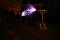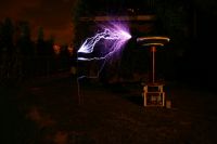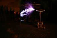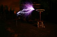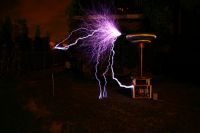
Huge DRSSTC Project
Dzejwor, Fri Mar 18 2011, 10:37PMHi. I plain to build next DRSSTC. This time something like steve's drsstc2. At first I have question about secondary and frez. Steve says on his website that he used 8inch pipe and 26awg wire and wound 2300 turns also wtites that the dimensions of toploads are 26"x4.5" and 44"x9" He writes that the resonance is approximately 45kHz but I get around 38kHz with those dimensios I think this is too low frez for this coil. Next question is MMC. I have 75pcs of CDE942C20P15K. What is better configuration of those caps - lower capacity higher voltage (5 in series and 15 strings 450n/10kV) or higher capacity lower voltage (4 in series 15 strings or more 563n/8kV with 15 strings of 4). I plain to push around 1200A in primary at 700-800V DC on the bridge. I plain to use predikter and CM300DY24 IGBTs. I don't have an idea for gate driver yet but I probably use step down GDT - something like 2:1:1:1:1 or 4:1:1:1:1 povered by intermediate mosfet bridge with another gdt. I dont want to use swithing power supplies and I'm not entirely convinced of the solid state gate drivers like steve do. Next I want to know what is the difference betwen CM300 igbts produced by Powerex and Mitsubishi. From what I usually see people use Powerex - why ? I have bricks from Mitsubishi - datasheets of Powerex and Mitsubishi are identical.
Re: Huge DRSSTC Project
Gregory, Fri Mar 18 2011, 11:45PM
Hey man, good talk about this because I am starting my new coil that is equal to your with same configuration and same IGBTs!!!
1 - The frequency never is low, the lower the better for yours IGBTs!
2 - The better configuration is the higher voltage AND the higher capacitance (if you want big arcs, for this size of coil use 500nF or more!), later I show how to calculate the MINIMUM MMC voltage.
3 - In my system I plan to use step-down GDT too: 2:1:1:1:1 with 48v at primary, it will have ~24V at gates. For me GDT is better, more simples and more reliability!
4 - I will use the same IGBT.. I don't know exactly what are the differences but I think that the powerex have more internal substrate it means that it will handle better the "overdrive". (we will run 1200A in a 600A device..)
**2** - To calculate the minimum MMC voltage you need to know the frequency you will run this, you said 38kHz I wil usel it for example:
First you calculate the MMC resistance (this resistance * the current that will generate the high voltage across it), the AC resistance of a capacitor is called *reactance* and can be calculated by this formula: ** Xc = 1 / (2*PI*F*C) **
Now you have the MMC AC resistance, using the standard ohm law you can discovery the voltage across the tank.
Knowing you said that will run 1200A (the result is more accuracy with the RMS current) and imagine you use 500nF MMC:
Xc = 1 / (2*PI*F*C)
Xc = 1 / (6.28 * 38*10^3 * 5 * 10^-7)
Xc = 8.37 ohm
Now we know that a 500nF MMC at 38kHz have an AC resistance of 8,37ohm
using ohm law:
U = 8.37 * 1200A
U = 10044V
Your MMC will have 10kV across the terminals!
Re: Huge DRSSTC Project
Dzejwor, Sat Mar 19 2011, 11:56AM
So I need more caps to build 10kV/540n MMC. I stil dont know what primary form is beter for this size of coil. I wonder between the cylindrical and conical. Conical look nice but is much more dificult to wind and I don't know how to define coupling. Cylindrical is easy to made. And next question - can I use wire with double (heavy) insulation or can it cause a significant deterioration in the secondary parameters ? (I have problem with buy wire with single insulation)
Re: Huge DRSSTC Project
Gregory, Sat Mar 19 2011, 03:48PM
1 - Yeah, the better for you is buy more caps
2 - I think that in my system I will use conical primary, I think is the best relation between k and flash-over problem. For calculate you can use the JavaTC, search in google.
3 - About the wire I don't know that is the differences of double insulation
Re: Huge DRSSTC Project
Steve Ward, Fri Mar 25 2011, 05:42PM
Though my website doesnt show it, all of my new coil designs use flat primaries. The coupling is generally high enough, and it has the best control of electric fields near the bottom of the coil, avoiding annoying flash-over between coils.
Also correct that the Fres stated at 45khz is off, its more like 41khz in real life (the actual # of turns is not counted, just calculated, so maybe its wrong). My DRSSTC-2 now uses a flat primary coil, ~10.5" ID and 23" OD with 9 turns of 3/8" copper tube. The smaller tube is actually about the same AC resistance as the 5/8" stuff i used originally, but with much less surface area to radiate heat i now must run water through the tubing to cool it. The original MMC made from the 942C series .15uF 2kV caps, has long since failed from overvoltage. I was running strings of 4 in series, but my the peak voltage across the caps was 9kV, so this was too much stress. The coil often is used for shows now, and its MMC has a 24kVDC rating, and operates at ~11kV peak, far higher reliability.
I made an experimental coil once with a 12" tube and 24awg wire, it resonated at ~35khz and with a flat primary achieved coupling of ~.18. This coil gave better performance with 12 foot sparks at 1500A primary current and ~5 - 8 kW (real power, not kVA) at 150-300bps. It also used a 1.25uF tank capacity and a short ON time of just 4 or 5 RF cycles. This mode of operation seemed efficient for long sparks with higher BPS, below ~150BPS the spark length would drop off dramatically, which might be considered a drawback.


Re: Huge DRSSTC Project
Dzejwor, Fri Mar 25 2011, 08:34PM
Nice to see your reply here Steve. Where do you get those big epson B25856 caps? I already have 90pcs of 942C and I realy dont want to kill them because they are very hard to buy and expensive in my country – not only 942C but generally capacitors suitable for drsstc. Largest expense in any of my coil, it is the capacitors. I build 540n/10kV cap and try to run my coil at 40-45kHz. Your flat primary looks very good. I try to make flat for my coil but I have some questions. First I dont like square bases but this square turn look cool I plain to build round so I make round safety turn too. I dont want to pump water through the winding for cooling so I use 15mm tubing (This is the typical diameter in my country what is near to your 5/8". The next available is 18mm). Plastic sheet on primary is only for visual or for flash-over protection ? Is there a simple method of determining the coupling ? For example when I use cylindrical primary I have around .18 if secondary starts at the same point where is the top end of primary. Ofcourse diameter of primary is important too – usualy around 2times bigger than secondary in my coils. I can calculate coupling using javatc but I don’t know how much it agrees with the real world.
I made some calculations using javatc and I get coupling around 0.133 with flat primary like Steve's but using 15mm (~5/8") copper and 0.3" space betwen turns - outer diameter increased to 27" with 9 turns and slightly smaller inner diameter. I have a little more Inductance. I plain to use dual toploads because I lkie them - they are look better than single topload ;) So my coil look now as follows:
primary:
ID: 10.3"
OD: 27"
9 Turns of 15mm (~5/8") tubing
Seconndary:
200mm (~8") PVC tube
~2300 turns of 26AWG copper wire
120cm (~47") height
Bigger topload:
Minor diameter: 6"
Major diameter: 43.3"
Smaller topload:
Minor diameter: 5"
Major diameter: 27.5"
Tank cap:
90psc of942C - 540n/10kV
Bridge and electronics:
2xCM300DY24
4x 3300u/450V electrolytics configured to 3300u/900V
2x 5uF/1kV Wima MKP snubbers
8or9x 100V TVS in series at all four IGBT's in bridge
Three phase supply with full wave rectifier - it should give around 600DCV with low pulsation. In future I maybe change them to the inverter supplying ~800VDC
Hammertone predikter drive with intermediate mosfet bridge and 2:1:1:1:1 GDT
Dzejwor, Fri Mar 25 2011, 08:34PM
Nice to see your reply here Steve. Where do you get those big epson B25856 caps? I already have 90pcs of 942C and I realy dont want to kill them because they are very hard to buy and expensive in my country – not only 942C but generally capacitors suitable for drsstc. Largest expense in any of my coil, it is the capacitors. I build 540n/10kV cap and try to run my coil at 40-45kHz. Your flat primary looks very good. I try to make flat for my coil but I have some questions. First I dont like square bases but this square turn look cool
 I plain to build round so I make round safety turn too. I dont want to pump water through the winding for cooling so I use 15mm tubing (This is the typical diameter in my country what is near to your 5/8". The next available is 18mm). Plastic sheet on primary is only for visual or for flash-over protection ? Is there a simple method of determining the coupling ? For example when I use cylindrical primary I have around .18 if secondary starts at the same point where is the top end of primary. Ofcourse diameter of primary is important too – usualy around 2times bigger than secondary in my coils. I can calculate coupling using javatc but I don’t know how much it agrees with the real world.
I made some calculations using javatc and I get coupling around 0.133 with flat primary like Steve's but using 15mm (~5/8") copper and 0.3" space betwen turns - outer diameter increased to 27" with 9 turns and slightly smaller inner diameter. I have a little more Inductance. I plain to use dual toploads because I lkie them - they are look better than single topload ;) So my coil look now as follows:
primary:
ID: 10.3"
OD: 27"
9 Turns of 15mm (~5/8") tubing
Seconndary:
200mm (~8") PVC tube
~2300 turns of 26AWG copper wire
120cm (~47") height
Bigger topload:
Minor diameter: 6"
Major diameter: 43.3"
Smaller topload:
Minor diameter: 5"
Major diameter: 27.5"
Tank cap:
90psc of942C - 540n/10kV
Bridge and electronics:
2xCM300DY24
4x 3300u/450V electrolytics configured to 3300u/900V
2x 5uF/1kV Wima MKP snubbers
8or9x 100V TVS in series at all four IGBT's in bridge
Three phase supply with full wave rectifier - it should give around 600DCV with low pulsation. In future I maybe change them to the inverter supplying ~800VDC
Hammertone predikter drive with intermediate mosfet bridge and 2:1:1:1:1 GDT
Re: Huge DRSSTC Project
Dzejwor, Thu Jun 30 2011, 10:57AM
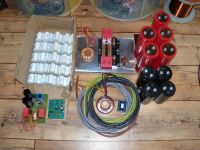
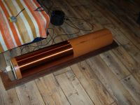
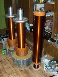
Hi. I colected some stuff and little changed parameters of my ciol. Now I have 100pcs of CDE and my MMC will be 600n/10kV. I get bigger electrolytic caps - 8200uF/400V and decided to make 4:1:1:1:1 GDT not 2:1:1:1:1 as I say before. Now I have finished secondary and collected all parts of electronic. I need to make toploads and primary and ofcourse put it all together I add some photos of my stuff
Dzejwor, Thu Jun 30 2011, 10:57AM
Hi. I colected some stuff and little changed parameters of my ciol. Now I have 100pcs of CDE and my MMC will be 600n/10kV. I get bigger electrolytic caps - 8200uF/400V and decided to make 4:1:1:1:1 GDT not 2:1:1:1:1 as I say before. Now I have finished secondary and collected all parts of electronic. I need to make toploads and primary and ofcourse put it all together
 I add some photos of my stuff


Re: Huge DRSSTC Project
Mads Barnkob, Thu Jun 30 2011, 01:32PM
I noticed that internal current limiting isn't mentioned anywhere in the datasheet for the CM300DY24, does this mean that it is born without it?
Mads Barnkob, Thu Jun 30 2011, 01:32PM
I noticed that internal current limiting isn't mentioned anywhere in the datasheet for the CM300DY24, does this mean that it is born without it?
Re: Huge DRSSTC Project
Kizmo, Thu Jun 30 2011, 02:51PM
Ward actually tested what this brick can survive in more or less typical drsstc conditions:

Kizmo, Thu Jun 30 2011, 02:51PM
Mads Barnkob wrote ...
I noticed that internal current limiting isn't mentioned anywhere in the datasheet for the CM300DY24, does this mean that it is born without it?
It does. I noticed that internal current limiting isn't mentioned anywhere in the datasheet for the CM300DY24, does this mean that it is born without it?
Ward actually tested what this brick can survive in more or less typical drsstc conditions:

Re: Huge DRSSTC Project
Finn Hammer, Thu Jun 30 2011, 02:52PM
Dzejwor,
Great to see the Predikter on a pro. quality board.
The predikter was designed to be used with discrete gate driver boards, using optical isolation on the timing signals. Due to a faulty gate driver design, I never dared to use the original gate drivers with any real power, so instead I used 1:4 gate transformer and intermediate bridge.
This solution has drawbacks, the main one being that the predikter puts out a very short, IRRC 10nS, pulse, after the last cycle in a burst. It is due to a delay on the interrupter pin, which allows the oscillator input to turn the gate driver chip "on" just briefly before it is turned "off" by the interrupter pin. This short pulse was drowned in delay on the optical link, but with a gate transformer it transfers enough energy to the gate transformer to create a huge and long ringing oscillation which looks really bad.
I fear that it could turn on the gates unsequenced.
Both Daniel's Diablo Tonnere and Thumper use this drive scheme, and we damped the oscillation with a 5W (I think 50ohm) resistor across the outputs. Not elegant, but it works..
There are 2 possible solutions, the one I prefer is to use the new Gate driver boards that I have designed, and I will let you have the design if you want to use them. Discrete gate driver boards means that you don't have to fiddle with gate resistor/diode networks, and you can really dial in the perfect non-ringing switch times.
Cheers, Finn Hammer
EDIT, I just notice that you have experience with the Predikter already. Did we talk about these issues already? Did you notice the "trapped ripple " ringing in the gate transformers?
-Finn
Re: Huge DRSSTC Project
Dzejwor, Thu Jun 30 2011, 09:26PM
Hi Finn
Yes I noticed this issue and I use damping resistors too - as you say: not so elegant but it works wery well. Somehow I can't trust the semiconductor gate drivers - I don't know why but I prefer old GDT's they are simple and there is nothing what can fail. But ofcourse if something go wrong this time I build your gatedrivers if you shared it for me. I have three other coils with Predikter and all work perfect - two big what you can see at photo and third small. That small coil work with predikter and ~ 180kHz Frez. Only thing what I needed to change is burden network connected to CTs.
Dzejwor, Thu Jun 30 2011, 09:26PM
Hi Finn
Yes I noticed this issue and I use damping resistors too - as you say: not so elegant but it works wery well. Somehow I can't trust the semiconductor gate drivers - I don't know why
 but I prefer old GDT's they are simple and there is nothing what can fail. But ofcourse if something go wrong this time I build your gatedrivers if you shared it for me. I have three other coils with Predikter and all work perfect - two big what you can see at photo and third small. That small coil work with predikter and ~ 180kHz Frez. Only thing what I needed to change is burden network connected to CTs.
Re: Huge DRSSTC Project
Dzejwor, Mon Jul 18 2011, 10:26AM
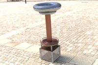
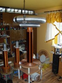
So I spent some time with SolidWorks and my coil should look like this:
Now I have finished bridge and MMC:
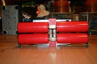
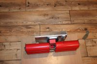
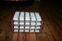
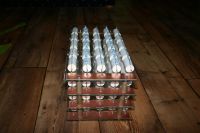
Dzejwor, Mon Jul 18 2011, 10:26AM
So I spent some time with SolidWorks and my coil should look like this:

Now I have finished bridge and MMC:


Re: Huge DRSSTC Project
Dzejwor, Thu Aug 11 2011, 03:40PM
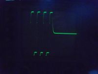
Finally, I ran all the electronics. Everything look good and work perfect. I probably get first light today or tomorow . But some things still are not leave me in peace. At first gate waveforms. They are look good for me but what is good for CM300 IGBTs ? I know I must turn off fast and turn on slow... But what is slow and not too slow ? Second thing is a crossconduction. How to measure it and what is good (It never be 0A ... ). Third thing is a current leading circuit. I testet a lot of inductors of diferent types and values but it still works best with a piece of wire coil wound on a finger. What exact inductor I should use for ~42kHz to get ~2uS current leading.
Some new pictures of my setup:
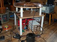
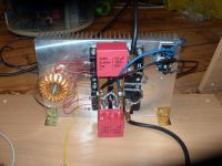
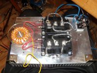
And CM300 Gate waveform - not so good quality
Dzejwor, Thu Aug 11 2011, 03:40PM
Finally, I ran all the electronics. Everything look good and work perfect. I probably get first light today or tomorow
 . But some things still are not leave me in peace. At first gate waveforms. They are look good for me but what is good for CM300 IGBTs ? I know I must turn off fast and turn on slow... But what is slow and not too slow ? Second thing is a crossconduction. How to measure it and what is good (It never be 0A ... ). Third thing is a current leading circuit. I testet a lot of inductors of diferent types and values but it still works best with a piece of wire coil wound on a finger. What exact inductor I should use for ~42kHz to get ~2uS current leading.
 Some new pictures of my setup:


And CM300 Gate waveform - not so good quality

Re: Huge DRSSTC Project
dude_500, Fri Aug 12 2011, 03:29AM
I definitely prefer optical and powered gate drivers over GDT's. I was able to tweak out just about all ringing, even on the first cycles. At full bus voltage, it only rings about 50V above bus. I've just never found this kind of timing precision to be possible on a GDT.
I also notice that brief gate pulse at the end of each interrupt cycle. It does propogate to my gates, but I've never seen it cause any problems, and surprisingly it doesn't ring at all at the nanoseconds later turn off.
It took a bit of doing to get the drivers working, but after about 2 months of R&D (and literally about 25 etched board prototypes), I now I have a flawless gate driver on a single sided board that screws to my IGBT's, has dropout protection to kill the whole coil softly, almost no ground loops, and transient protections everywhere possible. I've driven that coil to 5000A peak (don't even ask what was going through my mind when I drove it that high severely out of tune) on CM600's (on a prediktor driver), which burned out due to crappy 60hz GDT power supplies that weren't rated for the standoff when bus reached 1000V. I now have a bridge on 1700V/1000A bricks with isolated switching supplies for all four gate drivers. Hoping to fire that bridge up soon.
Bottom line, I hate GDT's and absolutely love discreet isolated gate drivers. I even used gate drive chips on a mini TO247 coil that fits an entire driver on a small computer heatsink.
dude_500, Fri Aug 12 2011, 03:29AM
Finn Hammer wrote ...
Dzejwor,
Great to see the Predikter on a pro. quality board.
The predikter was designed to be used with discrete gate driver boards, using optical isolation on the timing signals. Due to a faulty gate driver design, I never dared to use the original gate drivers with any real power, so instead I used 1:4 gate transformer and intermediate bridge.
This solution has drawbacks, the main one being that the predikter puts out a very short, IRRC 10nS, pulse, after the last cycle in a burst. It is due to a delay on the interrupter pin, which allows the oscillator input to turn the gate driver chip "on" just briefly before it is turned "off" by the interrupter pin. This short pulse was drowned in delay on the optical link, but with a gate transformer it transfers enough energy to the gate transformer to create a huge and long ringing oscillation which looks really bad.
I fear that it could turn on the gates unsequenced.
Both Daniel's Diablo Tonnere and Thumper use this drive scheme, and we damped the oscillation with a 5W (I think 50ohm) resistor across the outputs. Not elegant, but it works..
There are 2 possible solutions, the one I prefer is to use the new Gate driver boards that I have designed, and I will let you have the design if you want to use them. Discrete gate driver boards means that you don't have to fiddle with gate resistor/diode networks, and you can really dial in the perfect non-ringing switch times.
Cheers, Finn Hammer
EDIT, I just notice that you have experience with the Predikter already. Did we talk about these issues already? Did you notice the "trapped ripple " ringing in the gate transformers?
-Finn
I definitely prefer optical and powered gate drivers over GDT's. I was able to tweak out just about all ringing, even on the first cycles. At full bus voltage, it only rings about 50V above bus. I've just never found this kind of timing precision to be possible on a GDT.
I also notice that brief gate pulse at the end of each interrupt cycle. It does propogate to my gates, but I've never seen it cause any problems, and surprisingly it doesn't ring at all at the nanoseconds later turn off.
It took a bit of doing to get the drivers working, but after about 2 months of R&D (and literally about 25 etched board prototypes), I now I have a flawless gate driver on a single sided board that screws to my IGBT's, has dropout protection to kill the whole coil softly, almost no ground loops, and transient protections everywhere possible. I've driven that coil to 5000A peak (don't even ask what was going through my mind when I drove it that high severely out of tune) on CM600's (on a prediktor driver), which burned out due to crappy 60hz GDT power supplies that weren't rated for the standoff when bus reached 1000V. I now have a bridge on 1700V/1000A bricks with isolated switching supplies for all four gate drivers. Hoping to fire that bridge up soon.
Bottom line, I hate GDT's and absolutely love discreet isolated gate drivers. I even used gate drive chips on a mini TO247 coil that fits an entire driver on a small computer heatsink.
Re: Huge DRSSTC Project
Arcstarter, Fri Aug 12 2011, 05:04AM
Looks great so far
You do have some overshoot on the gates. While it may not be problematic, i always try to get as close to a perfect square as i can. The leads on your GDT (especially primary) are somewhat long, so that could be causing the overshoot.
The rise time also looks a tiny bit slower than ideal, which also may not be a problem, but i really split hairs when it comes to the health of bricks. You seem to have some resistors in series with the primary, though i may be wrong. I would omit those, unless you get unbearable ringing without them. It takes a fair bit of peak power to drive a gate that is around 50-100nf. A slower rise time could just generate more heat, which while may not really cause problems, could require you to use an otherwise unnecessary amount of cooling.
Arcstarter, Fri Aug 12 2011, 05:04AM
Looks great so far

You do have some overshoot on the gates. While it may not be problematic, i always try to get as close to a perfect square as i can. The leads on your GDT (especially primary) are somewhat long, so that could be causing the overshoot.
The rise time also looks a tiny bit slower than ideal, which also may not be a problem, but i really split hairs when it comes to the health of bricks. You seem to have some resistors in series with the primary, though i may be wrong. I would omit those, unless you get unbearable ringing without them. It takes a fair bit of peak power to drive a gate that is around 50-100nf. A slower rise time could just generate more heat, which while may not really cause problems, could require you to use an otherwise unnecessary amount of cooling.
Re: Huge DRSSTC Project
Finn Hammer, Fri Aug 12 2011, 06:48AM
I use 5.5uH of these @34kHz, and there should be ample delay in the predikter board for that, even at higher frequencies.
This type of coils come from many different manufacturers, but they all seem to work fine. I like them since the coil is shielded inside the ferrite loop.
Cheers, Finn Hammer
Finn Hammer, Fri Aug 12 2011, 06:48AM
Dzejwor wrote ...
What exact inductor I should use for ~42kHz to get ~2uS current leading.
What exact inductor I should use for ~42kHz to get ~2uS current leading.
I use 5.5uH of these
 @34kHz, and there should be ample delay in the predikter board for that, even at higher frequencies.
This type of coils come from many different manufacturers, but they all seem to work fine. I like them since the coil is shielded inside the ferrite loop.
Cheers, Finn Hammer
Re: Huge DRSSTC Project
Finn Hammer, Fri Aug 12 2011, 07:25AM
My latest setup also includes discrete gate drivers, isolated with optocouplers on the signal, which solves the problem with the rookie peak at the end of each cycle. Boards are powered with discrete boost converters to insure full supply even at brownout.
However, all this finery, I think it reveals my level of OCD instead of the "let good enough be good enough" attitude of those builders whose coils are making sparks all day
End of rant, Finn Hammer
Finn Hammer, Fri Aug 12 2011, 07:25AM
dude_500 wrote ...
I definitely prefer optical and powered gate drivers over GDT's. I was able to tweak out just about all ringing, even on the first cycles. At full bus voltage, it only rings about 50V above bus. I've just never found this kind of timing precision to be possible on a GDT.
I also notice that brief gate pulse at the end of each interrupt cycle. It does propogate to my gates, but I've never seen it cause any problems, and surprisingly it doesn't ring at all at the nanoseconds later turn off.
It took a bit of doing to get the drivers working, but after about 2 months of R&D (and literally about 25 etched board prototypes), I now I have a flawless gate driver on a single sided board that screws to my IGBT's, has dropout protection to kill the whole coil softly, almost no ground loops, and transient protections everywhere possible. I've driven that coil to 5000A peak (don't even ask what was going through my mind when I drove it that high severely out of tune) on CM600's (on a prediktor driver), which burned out due to crappy 60hz GDT power supplies that weren't rated for the standoff when bus reached 1000V. I now have a bridge on 1700V/1000A bricks with isolated switching supplies for all four gate drivers. Hoping to fire that bridge up soon.
Bottom line, I hate GDT's and absolutely love discreet isolated gate drivers. I even used gate drive chips on a mini TO247 coil that fits an entire driver on a small computer heatsink.
My latest setup also includes discrete gate drivers, isolated with optocouplers on the signal, which solves the problem with the rookie peak at the end of each cycle. Boards are powered with discrete boost converters to insure full supply even at brownout.
However, all this finery, I think it reveals my level of OCD instead of the "let good enough be good enough" attitude of those builders whose coils are making sparks all day

End of rant, Finn Hammer
Re: Huge DRSSTC Project
Herr Zapp, Fri Aug 12 2011, 07:30PM
Finn -
Probably not really accurate to label OC Engineering as a "disorder".
Possibly OCEP (obsessive/compulsive Engineering perfection) or OCES (obsessive/compulsive Engineering sophistication).
Herr Zapp
Herr Zapp, Fri Aug 12 2011, 07:30PM
Finn -
Probably not really accurate to label OC Engineering as a "disorder".
Possibly OCEP (obsessive/compulsive Engineering perfection) or OCES (obsessive/compulsive Engineering sophistication).
Herr Zapp
Re: Huge DRSSTC Project
Arcstarter, Fri Aug 12 2011, 08:44PM
Arcstarter, Fri Aug 12 2011, 08:44PM
Finn Hammer wrote ...
I use 5.5uH of these @34kHz, and there should be ample delay in the predikter board for that, even at higher frequencies.
This type of coils come from many different manufacturers, but they all seem to work fine. I like them since the coil is shielded inside the ferrite loop.
Cheers, Finn Hammer
What i did was take one of those can type variable inductors with the ferrite tuning slug (this one has static and magnetic shielding) and rewound it with 24 turns of 32 gauge. It seems to have a good tuning range for my IGBT and frequency, and the tuning slug about right in the middle is where the phase lead seems to be perfect. I used a 4.7 ohm 1-2w carbon film shunt resistor in series with said inductor.Dzejwor wrote ...
What exact inductor I should use for ~42kHz to get ~2uS current leading.
What exact inductor I should use for ~42kHz to get ~2uS current leading.
I use 5.5uH of these
 @34kHz, and there should be ample delay in the predikter board for that, even at higher frequencies.
This type of coils come from many different manufacturers, but they all seem to work fine. I like them since the coil is shielded inside the ferrite loop.
Cheers, Finn Hammer
Re: Huge DRSSTC Project
Dzejwor, Fri Aug 12 2011, 08:46PM
So I can't make shorter connection betwen GDT and driver but i can (and I do) shorter connections betwen gdt and gates. Now I have 10ohm gate resistors bypased by 1N5819diodes. I dont have any resistance in series with primary but I have parallel - must have it to dump ringing after last cycle. I have three other coils with predikter here and all have this dumping resistors at gdt primary. I have 4:1:1:1:1 GDT and its impedance can be too high I have around 20 turns on huge TX52 core made of 3E25 ferrite - it is probably strongly oversized but as I alaways say - better too big than too small

Re: Huge DRSSTC Project
Dzejwor, Tue Aug 16 2011, 09:28PM
So my first light was delayed by bad weather and rain I ran my coil first time today and I'm not especially satisfied with the results. I dont know how exact tune that coil. I set the ocd to 1kA but current wont ringup as high. Now I can only put ~250VAC from the variac maybe this is my problem - too low bus voltage. Can someone show me proper primary current waveform with the secondary ? I see something strange - ringdown after last cucle looks like it has changed the phase after some cycles. I dont have picture but I get when i run next time - maybe tomorow if not it will rain. I add vide from today:

Re: Huge DRSSTC Project
Goodchild, Wed Aug 17 2011, 03:19PM
That looks ok, I bet you just need more bus voltage! I run 650VDC on my big DRSSTC to get 12 feet.
Here is a proper DRSSTC ring up and ring down with no secondary in place
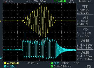
The changing phase you see at the end is the point at which the IGBTs stop driving and the diodes start back rectifying the energy left in the tank circuit back into the bus capacitor.
Keep in mind though that the ring up and ring down with charge depending on how you have it tuned and the coupling factor.
Good luck with next test!
Goodchild, Wed Aug 17 2011, 03:19PM
Dzejwor wrote ...
So my first light was delayed by bad weather and rain I ran my coil first time today and I'm not especially satisfied with the results. I dont know how exact tune that coil. I set the ocd to 1kA but current wont ringup as high. Now I can only put ~250VAC from the variac maybe this is my problem - too low bus voltage. Can someone show me proper primary current waveform with the secondary ? I see something strange - ringdown after last cucle looks like it has changed the phase after some cycles. I dont have picture but I get when i run next time - maybe tomorow if not it will rain. I add vide from today:
So my first light was delayed by bad weather and rain I ran my coil first time today and I'm not especially satisfied with the results. I dont know how exact tune that coil. I set the ocd to 1kA but current wont ringup as high. Now I can only put ~250VAC from the variac maybe this is my problem - too low bus voltage. Can someone show me proper primary current waveform with the secondary ? I see something strange - ringdown after last cucle looks like it has changed the phase after some cycles. I dont have picture but I get when i run next time - maybe tomorow if not it will rain. I add vide from today:

That looks ok, I bet you just need more bus voltage! I run 650VDC on my big DRSSTC to get 12 feet.
Here is a proper DRSSTC ring up and ring down with no secondary in place

The changing phase you see at the end is the point at which the IGBTs stop driving and the diodes start back rectifying the energy left in the tank circuit back into the bus capacitor.
Keep in mind though that the ring up and ring down with charge depending on how you have it tuned and the coupling factor.
Good luck with next test!
Re: Huge DRSSTC Project
Dzejwor, Wed Aug 17 2011, 06:02PM
Yes I know this but I see something diferent than in my other coils in current ringdown. I show this later now I go outside to make some tests with doubler and higher bus voltage. Ofcourde my waveforms without primary are good.
Dzejwor, Wed Aug 17 2011, 06:02PM
Yes I know this but I see something diferent than in my other coils in current ringdown. I show this later now I go outside to make some tests with doubler and higher bus voltage. Ofcourde my waveforms without primary are good.
Re: Huge DRSSTC Project
Dzejwor, Wed Aug 17 2011, 07:12PM
If I put secondary in place I have something like this it is strange to me in other coils I always had diferent ringdown - like without primary but with notches. I twas get at around 100V bus voltage.
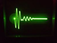
My scope fails again but it's not important now this is time base generator.
So I test rail voltage up to the 660V with no problems using voltage doubler but I stil need more tunning. I cant break 2.5m (8.2 feet). Video from today tests:
Dzejwor, Wed Aug 17 2011, 07:12PM
If I put secondary in place I have something like this it is strange to me in other coils I always had diferent ringdown - like without primary but with notches. I twas get at around 100V bus voltage.

My scope fails again but it's not important now this is time base generator.
So I test rail voltage up to the 660V with no problems using voltage doubler but I stil need more tunning. I cant break 2.5m (8.2 feet). Video from today tests:

Re: Huge DRSSTC Project
Gregory, Wed Aug 17 2011, 11:27PM
You only need more tune. Appear that you need to low your primary fres to get in tune, allowing the corona charge to put it in tune
Gregory, Wed Aug 17 2011, 11:27PM
You only need more tune. Appear that you need to low your primary fres to get in tune, allowing the corona charge to put it in tune
Re: Huge DRSSTC Project
Goodchild, Thu Aug 18 2011, 12:02AM
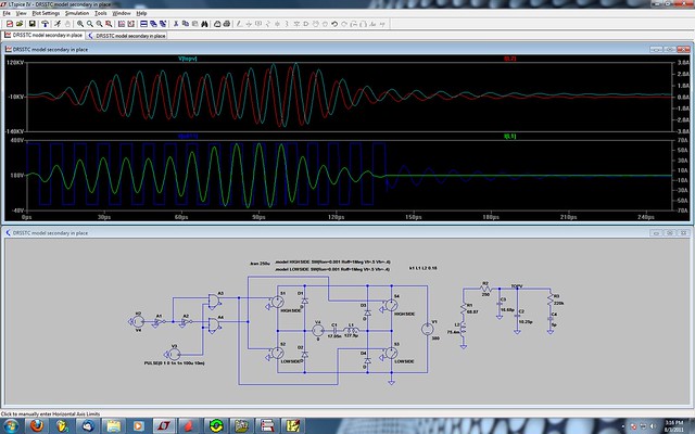
I agree with Gregory, tuning is most likely your issue. If tuned and coupled in particulate ways you can see "notches" form in the primary current similar to what you are seeing now. These notches would only occur with the secondary in place because it's a function of coupling and tuning and not just one.
You can see a notch starting to form in primary current in this simulation of a DR:

Re: Huge DRSSTC Project
StevenCaton, Sat Aug 20 2011, 08:59PM
Dang Eric, there you go again whippin out ur complicated simulations.
StevenCaton, Sat Aug 20 2011, 08:59PM
Dang Eric, there you go again whippin out ur complicated simulations.

Re: Huge DRSSTC Project
Dzejwor, Fri Aug 26 2011, 07:31PM
So after some tests I came to the conclusion that my waveforms are not as good as I thought before. I have some bad oscilations at output voltage and slev rate on the gates are to low - 500ns falltime and around 2uS rise time. So I must redesign GDT or whole gate driver but I dont know how. What is the best way to make goodworking GDT ? I think my core is not so good for this job. I use TX58/41/18 made of 3E25 material - They work wery good in my smalest coils. Here is core datasheet and material
What material will be better ? I can get 3C90 or 3F3 other will be dificult to buy in my country Is there a better method of winding 4:1:1:1:1 GDT ? I make four twisted pairs of wires and twist them together. one wire of each pair is my secondary second is part of four times longer primary. I see Finn's GDTs and they look similar.
Dzejwor, Fri Aug 26 2011, 07:31PM
So after some tests I came to the conclusion that my waveforms are not as good as I thought before. I have some bad oscilations at output voltage and slev rate on the gates are to low - 500ns falltime and around 2uS rise time. So I must redesign GDT or whole gate driver but I dont know how. What is the best way to make goodworking GDT ? I think my core is not so good for this job. I use TX58/41/18 made of 3E25 material - They work wery good in my smalest coils. Here is core datasheet
 and material
What material will be better ? I can get 3C90 or 3F3 other will be dificult to buy in my country
 Is there a better method of winding 4:1:1:1:1 GDT ? I make four twisted pairs of wires and twist them together. one wire of each pair is my secondary second is part of four times longer primary. I see Finn's GDTs and they look similar.
Re: Huge DRSSTC Project
Goodchild, Sat Aug 27 2011, 06:10AM
Steve you know how much I love my squiggly lines...
Goodchild, Sat Aug 27 2011, 06:10AM
SteveCaton wrote ...
Dang Eric, there you go again whippin out ur complicated simulations.
Dang Eric, there you go again whippin out ur complicated simulations.

Steve you know how much I love my squiggly lines...

Print this page
