
Vacuum Rectifiers X-rays report
radhoo, Sat Jan 15 2011, 11:20PMSee the following posts for the lastest results. Here is just a quick insight of the current status:
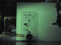
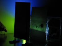
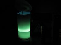
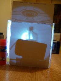
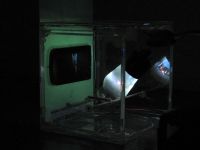
Photo 1: 2X2 tube, inverse polarization (HV+ to Tube pins, HV- to Anode) 50KV, 15 s exposure, f/3.5, ISO 100.
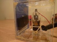
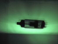
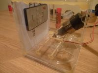
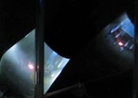
Photo 2: same, different setup
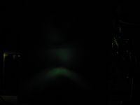
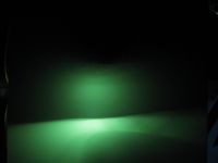
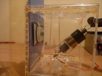
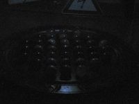
Photo 3: determining the x-ray distribution field test
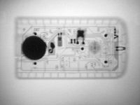
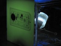
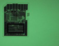
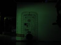
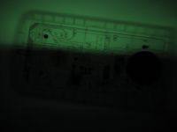
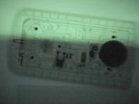
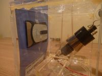
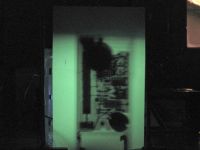
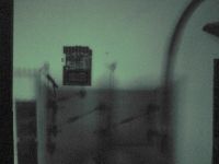
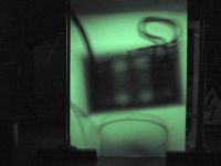
Photo 1&2: The same remote control while being illuminated by the 2X2
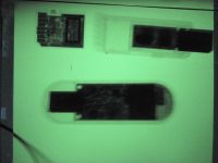
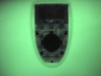
Photo 3: SDCard
Comments: For this thread I will be using various vacuum rectifier tubes, for the purpose of checking the X-Ray emission in cases of over-voltage. I will try to indicate the field distribution, best angles, and other details, but these take a lot of time, so this thread is work under progress.
Each of my experiments will be indexed like 01, 02, etc. I will also indicate the tube used, the voltage level, whether it was connected in normal polarization (meaning the Supply HV+ goes to tubes Anode) or inverse polarization (HV+ goes to the tube's bottom pins, connected together, and HV- goes to the Tube's anode). Also photography details such as fluorescent screen type, camera, exposure times, will be indicated.
Safety: There will be an entire post dedicated to safety below, however I should point out that all my tests are performed remotely, and the camera is set on a tripod, with a timer. I also use a few dosimeters to at least indicate the presence of x-rays, since they are not well suited for dosing the emission: Radex 1706 (30keV minimum sensitivity), Terra-P, Kvarts DRSB01, CDV 700.
Power supply : I'm currently using my DIY 50KV Variable supply:
 (ZVS+Multiplier in paraffin). For all the tests below, unless otherwise indicated, the complete system is powered from a regulated variable DC supply (
  ), currently set at 12V (20amps max). Very little power , this could easily run on battery!
01.First Tests
Note: This first test uses a 2X2 connected in normal polarization.
Objective 1: demonstrate x-ray emission.
Objective 2: Verify the x-ray level is suitable for photography
Thanks for Proud Mary for discussing the characteristics of the 2x2 Russian rectifier:

I recently acquired a few of these tubes, so I run a few tests of over-volting them using my 50KV supply:
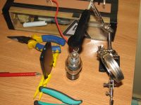
The system was triggered remotely, from safe distance (more then 6 meters) with concrete walls in between. The camera used to capture the results is a Canon S2 IS, operated using the timer function. The camera was set on a tripod, at 1.5meters away from the 2X2, and the zoom set to maximum. Focus was set to manual.
For these first tests, a limiting resistor was added in series with the supply. The tube's anode was connected to positive.
A Radex 1706 dosimeter, set in close proximity of the tube (15cm), indicated more the 800uSv/h in just 3 seconds of operation. At aprox. 80cm, the value dropped to 200uSv/h (Background level 0.13uSv/h). At two meters, the Radex was still detecting a high level. The datasheet of this dosimeter indicates it is capable of detecting X-rays of minimum 30keV.
The purpose of these tests was to determine if a radiography is at least possible using this setup. Fluorescent screens of 4 different types where used:
1. A first test, to see if the fluorescent screen emits any light:
8 seconds exposure, f/3.5 (not so good camera), ISO 400 (very noisy on this camera).
2. An object (a remote control) was added between the 2X2 and the fluorescent screen. For all the pictures here, the fluorescent screen was placed immediately after the remote control, and the distance from the tube was 5-8cm:
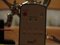
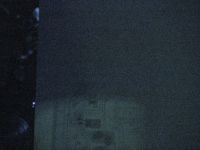
Exposure: 10s , f/3.5, ISO 400 , Green emitting fluorescent screen 1 (will add type later)
3. Using a blue emitting fluorescent screen:
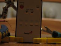
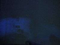
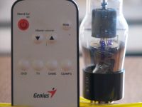
Exposure: 10s , f/3.5, ISO 400 (Bad, bad camera).
4.Another one:
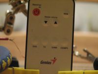


Exposure: 15s , f/3.5, ISO 400
TODO:
- a lot!
- build a container for the 2x2, filled with oil for cooling, since the tube is getting quite hot even if operated for only a few seconds
- try the tube with reversed polarity
- use lead sheet over the oil container and tube, with a small orifice to control the emission geometry
- place a micro-ampmeter in series with this setup
- dare to use the DSLR for a few shots? or maybe not.
- measure the radiation levels, in relation with the distance - estimate the safety levels
- build a few more detectors
- or -
put all the setup in a lead box.
- get a better x-ray tube
- is there anything else? comments? thanks!
Re: Vacuum Rectifiers X-rays report
radhoo, Sun Jan 16 2011, 10:55AM
[-]
radhoo, Sun Jan 16 2011, 10:55AM
[-]
Re: Vacuum Rectifiers X-rays report
Proud Mary, Sun Jan 16 2011, 11:32AM
If the figure of 800 μSv/h at 15cm is roughly correct, and you do have 50kV on the diode anode, then the field emission current through the 2X2 is much less than 1μA.
The X-ray energy response of GM tubes below 100keV is very non-linear, so your actual dose rate may be smaller than this. It says a lot for the intensifying screen that it is able to function with such low fluence.
You may be able to influence the electron stream with one or more strong external magnets, and so give the beam better directional properties.
The image curvature or convexity at the upper edge shows the shadow the anode bell very clearly, as I showed you some weeks ago in a diagram.
I am intrigued by the fate of electrons hitting the very edge of the anode bell at a 'grazing' incidence.
PS Added Later. Don't forget you can use an ordinary mechanic's feeler gauge set as a penetrameter, or use strips of ordinary kitchen aluminium foil in layers if your rays are too soft even for the thinnest of the steel feeler gauges.
Re: Vacuum Rectifiers X-rays report
vircator, Sun Jan 16 2011, 03:39PM
Can you point us to a source for the Fluorescent screens you used? Thanks
vircator, Sun Jan 16 2011, 03:39PM
Can you point us to a source for the Fluorescent screens you used? Thanks
Re: Vacuum Rectifiers X-rays report
radhoo, Sun Jan 16 2011, 03:58PM
radhoo, Sun Jan 16 2011, 03:58PM
vircator wrote ...
Can you point us to a source for the Fluorescent screens you used? Thanks
They were taken out of X-ray cassettes. You can find them on Ebay or maybe you have a friend doctor (thanks vasil).Can you point us to a source for the Fluorescent screens you used? Thanks
Re: Vacuum Rectifiers X-rays report
radhoo, Mon Jan 17 2011, 12:17AM
02.Experiment inverse polarization
Note: Tube used 2X2. The tube was position at a very small angle from the screen plan normal, at a distance of 4cm.
Objective: compare the normal polarization emission with inverse polarization
The first image was taken with the 2X2 tube powered by connecting HV+ to Anode. The second picture has the connections reversed, the 2X2 has the anode connected to HV- , and the bottom pins connected together to HV+. The difference is obvious.
So using this reversed connection, here are some results:

The quality is good enough to actually use this radiograph for seeing the internals. A very cheap solution for a reasonably good image.
The 2X2 gets hot very quickly, the 15seconds needed for camera exposure are the maximum I would go for. Putting it under oil would improve this issue.
radhoo, Mon Jan 17 2011, 12:17AM
02.Experiment inverse polarization
Note: Tube used 2X2. The tube was position at a very small angle from the screen plan normal, at a distance of 4cm.
Objective: compare the normal polarization emission with inverse polarization
The first image was taken with the 2X2 tube powered by connecting HV+ to Anode. The second picture has the connections reversed, the 2X2 has the anode connected to HV- , and the bottom pins connected together to HV+. The difference is obvious.


So using this reversed connection, here are some results:


The quality is good enough to actually use this radiograph for seeing the internals. A very cheap solution for a reasonably good image.

The 2X2 gets hot very quickly, the 15seconds needed for camera exposure are the maximum I would go for. Putting it under oil would improve this issue.
Re: Vacuum Rectifiers X-rays report
Wolfram, Mon Jan 17 2011, 07:42AM
That's not bad at all. It's the best result I've seen from operating a rectifier tube in cold cathode mode.
Wolfram, Mon Jan 17 2011, 07:42AM
That's not bad at all. It's the best result I've seen from operating a rectifier tube in cold cathode mode.
Re: Vacuum Rectifiers X-rays report
radhoo, Mon Jan 17 2011, 12:06PM
Here is the last radiograph, with the exposure/gamma/brightness adjusted by software:

radhoo, Mon Jan 17 2011, 12:06PM
Anders M. wrote ...
That's not bad at all. It's the best result I've seen from operating a rectifier tube in cold cathode mode.
Thank you, Anders M., I can only take your words as an encouragement to move further.That's not bad at all. It's the best result I've seen from operating a rectifier tube in cold cathode mode.
Here is the last radiograph, with the exposure/gamma/brightness adjusted by software:

Re: Vacuum Rectifiers X-rays report
radhoo, Mon Jan 17 2011, 12:40PM
03.6LJ6A (lead glass)
Note: n/a
Objective: Use a 6LJ6A shunt with Lead Glass in inverse polarization setup with the 50KV source and check the x-ray emission as recorded by the camera . No dosimeter data available here.
Result: No emission -or- emission too weak.
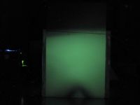
The two objects are seen on the fluorescent screen, only as shadows, from the UV light generated inside the tube.
radhoo, Mon Jan 17 2011, 12:40PM
03.6LJ6A (lead glass)
Note: n/a
Objective: Use a 6LJ6A shunt with Lead Glass in inverse polarization setup with the 50KV source and check the x-ray emission as recorded by the camera . No dosimeter data available here.


Result: No emission -or- emission too weak.
The two objects are seen on the fluorescent screen, only as shadows, from the UV light generated inside the tube.
Re: Vacuum Rectifiers X-rays report
radhoo, Mon Jan 17 2011, 01:05PM
04.Some "measurements"
Note: Tube 2X2 in normal polarization at 50KV.
While waiting for a proper lead box to encapsulate this x-ray machine, here are some measurements. Unfortunately they seem to be quite unreliable. I might say that the best detector at this point, seems to be the fluorescent screen+camera. One of my new tests will be a box made of fluorescent screens, with tube placed inside, to be a better idea of the field distribution and intensity.
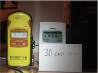
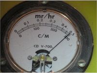
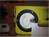
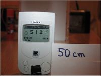
These devices are not suited for dosing the X-Rays, they might work for detecting them, but might not work at all. So they have to be considered unreliable.
Picture 1: Radex 1706 and Terra-P Geiger Counters at 30 cm . The Radex seems to get saturated very quickly.
Picture 2: A CDV 700 Geiger counter set to x100 Scale.
Picture 3: A CDV 717 Ionisation chamber detector, set to x0.1 Scale, and placed at 15cm from 2X2.
Picture 4: The Radex 1706 at 50cm going for saturation
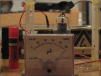
Picture 5: A 100uAmpmeter connected in series, goes past scale. Note the circuit is as follows:
(-)Bipolar HV Supply 50KV (+) ----> HV Limiting resistor ----> 2X2 Tube anode
|
|------> 100uAmpmeter--------------------------------> 2X2 Bottom pins together.
Could use some suggestions here. Thanks!
radhoo, Mon Jan 17 2011, 01:05PM
04.Some "measurements"
Note: Tube 2X2 in normal polarization at 50KV.
While waiting for a proper lead box to encapsulate this x-ray machine, here are some measurements. Unfortunately they seem to be quite unreliable. I might say that the best detector at this point, seems to be the fluorescent screen+camera. One of my new tests will be a box made of fluorescent screens, with tube placed inside, to be a better idea of the field distribution and intensity.


These devices are not suited for dosing the X-Rays, they might work for detecting them, but might not work at all. So they have to be considered unreliable.
Picture 1: Radex 1706 and Terra-P Geiger Counters at 30 cm . The Radex seems to get saturated very quickly.
Picture 2: A CDV 700 Geiger counter set to x100 Scale.
Picture 3: A CDV 717 Ionisation chamber detector, set to x0.1 Scale, and placed at 15cm from 2X2.
Picture 4: The Radex 1706 at 50cm going for saturation

Picture 5: A 100uAmpmeter connected in series, goes past scale. Note the circuit is as follows:
(-)Bipolar HV Supply 50KV (+) ----> HV Limiting resistor ----> 2X2 Tube anode
|
|------> 100uAmpmeter--------------------------------> 2X2 Bottom pins together.
Could use some suggestions here. Thanks!
Re: Vacuum Rectifiers X-rays report
radhoo, Mon Jan 17 2011, 02:06PM
05.A Field distribution test
Note: A 2X2 Tube in inverse polarization at 50KV, placed with the anode towards the fluorescent screen (perpendicular on the screen's surface):
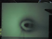
Distance between tube end and screen: 3cm .
Comments: if the central black spot is probably a shadow caused by the metallic anode cap, then what is the bigger concentric shadow ring?
radhoo, Mon Jan 17 2011, 02:06PM
05.A Field distribution test
Note: A 2X2 Tube in inverse polarization at 50KV, placed with the anode towards the fluorescent screen (perpendicular on the screen's surface):


Distance between tube end and screen: 3cm .
Comments: if the central black spot is probably a shadow caused by the metallic anode cap, then what is the bigger concentric shadow ring?
Re: Vacuum Rectifiers X-rays report
radhoo, Mon Jan 17 2011, 02:32PM
I already said that IMO the CCDs + fluorescent screens offer a great potential in detecting and dosing the X-rays. Here's the last image again, with two levels of segmentation (threshold) applied. In image processing, threshold is a segmentation process in which only the pixels with a high enough intensity pass (bigger then the configured threshold) and are market as white, the others are market as black.
So by adjusting the threshold it is possible to observe the more intense spots as captured by the digital camera. This not only shows where the field is more intense, but it also helps in observing the distribution field. As stated previously, a needed next step is to enclose the tube totally in Fluorescent material, and to record a 360 degrees image.
With the image above, it is possible to observe the tube has a stronger emission in the left half, then it has in the right one as per the presented position:



Central picture shows the area with the most intense emission.
radhoo, Mon Jan 17 2011, 02:32PM
I already said that IMO the CCDs + fluorescent screens offer a great potential in detecting and dosing the X-rays. Here's the last image again, with two levels of segmentation (threshold) applied. In image processing, threshold is a segmentation process in which only the pixels with a high enough intensity pass (bigger then the configured threshold) and are market as white, the others are market as black.
So by adjusting the threshold it is possible to observe the more intense spots as captured by the digital camera. This not only shows where the field is more intense, but it also helps in observing the distribution field. As stated previously, a needed next step is to enclose the tube totally in Fluorescent material, and to record a 360 degrees image.
With the image above, it is possible to observe the tube has a stronger emission in the left half, then it has in the right one as per the presented position:


Central picture shows the area with the most intense emission.
Re: Vacuum Rectifiers X-rays report
Proud Mary, Mon Jan 17 2011, 03:07PM
I don't think it right to call any of these indications 'measurements.' You have used equipment which you knew to be unsuited to the measurement of X-rays below 50keV, and now you ask why the indications on these useless instruments are all in disagreement.
The best use for the yellow brick with the handle on it? Paint it black and use it as a weight for eel fishing in the Dunărea.
Proud Mary, Mon Jan 17 2011, 03:07PM
radhoo wrote ...
04.Some measurements
04.Some measurements
I don't think it right to call any of these indications 'measurements.' You have used equipment which you knew to be unsuited to the measurement of X-rays below 50keV, and now you ask why the indications on these useless instruments are all in disagreement.
The best use for the yellow brick with the handle on it? Paint it black and use it as a weight for eel fishing in the Dunărea.
Re: Vacuum Rectifiers X-rays report
radhoo, Mon Jan 17 2011, 03:32PM
Even if the indications are totally inaccurate, the values indicated are related to the distance, so I can at least see where the field is not so hot/active/counts producing.
radhoo, Mon Jan 17 2011, 03:32PM
Proud Mary wrote ...
I don't think it right to call any of these indications 'measurements.' You have used equipment which you knew to be unsuited to the measurement of X-rays below 50keV, and now you ask why the indications on these useless instruments are all in disagreement.
The best use for the yellow brick with the handle on it? Paint it black and use it as a weight for eel fishing in the Dunărea.
Besides the saturation in close proximity of the tube, I had some good use of the RD1706: Moving it further allowed this detector/indicator to function a little better: By doing so, the RD1706 showed an expected lower radiation level, as per the distance increment. It also has a very loud beep that goes on as soon as I power the tube which is also useful as a warning. I don't think it right to call any of these indications 'measurements.' You have used equipment which you knew to be unsuited to the measurement of X-rays below 50keV, and now you ask why the indications on these useless instruments are all in disagreement.
The best use for the yellow brick with the handle on it? Paint it black and use it as a weight for eel fishing in the Dunărea.
Even if the indications are totally inaccurate, the values indicated are related to the distance, so I can at least see where the field is not so hot/active/counts producing.
Re: Vacuum Rectifiers X-rays report
Proud Mary, Mon Jan 17 2011, 03:49PM
I think these experiments mapping the X-ray emission lobes of the 2X2 are both new and excellent, but you must sort out your dosimetry and shielding issues or your fingers will turn into bratwurst, my friend:

Proud Mary, Mon Jan 17 2011, 03:49PM
I think these experiments mapping the X-ray emission lobes of the 2X2 are both new and excellent, but you must sort out your dosimetry and shielding issues or your fingers will turn into bratwurst, my friend:

Re: Vacuum Rectifiers X-rays report
radhoo, Mon Jan 17 2011, 04:19PM
A bit offtopic but,
All tests are performed remotely. Basically the setup is in a different room, 6 meters from where I am, two walls in between, one of them made of concrete and steel 15cm tick. So my fingers should stay safe. If there was a such a risk, I would never run these tests.
Re: Vacuum Rectifiers X-rays report
Proud Mary, Tue Jan 18 2011, 04:02PM
Those bratwurst do look good, don't they?
Thinking about the concentric shadow surrounding the anode shadow in your radiograph, I wonder if it can be the longitudinal shadow of the anode bell from X-ray photons produced by field electron impacts on the circular shielding plate?
It certainly is an interesting feature worth investigating. If you have a good magnet, and place it near the shielding plate it might cause sufficient disturbance of the field emission electrons to show up on the radiograph
Proud Mary, Tue Jan 18 2011, 04:02PM
Those bratwurst do look good, don't they?

Thinking about the concentric shadow surrounding the anode shadow in your radiograph, I wonder if it can be the longitudinal shadow of the anode bell from X-ray photons produced by field electron impacts on the circular shielding plate?
It certainly is an interesting feature worth investigating. If you have a good magnet, and place it near the shielding plate it might cause sufficient disturbance of the field emission electrons to show up on the radiograph
Re: Vacuum Rectifiers X-rays report
radhoo, Tue Jan 18 2011, 05:42PM
I have a few Neodymium n48 magnets, that I can use for this purpose. Probably this evening I will run some more tests.
Some other ideas:
- re-test my NaI scintillation probe with this x-ray emitting setup
- try to identify a correlation between photon energy and : 1) pixel intensity in camera images -or- 2) scintillation amplitude (in an effort to get the dosimetry on the right direction) . There are issues with both I will see what I can come up with.
- test some other vacuum rectifier tubes (I got a few, hope there are some without lead glass as well).
- use aluminum foil for hardening the beam and see how that works .
Interesting to see how well the lead-glass works for shielding! See the 03.6LJ6A above.
Re: Vacuum Rectifiers X-rays report
Arcstarter, Tue Jan 18 2011, 08:50PM
Great thread, Radu! This thread will be priceless for the project i am working on, which is an experimental x-ray machine like yours, with a high voltage stabilizer. I would like to get some rectifier tubes and test them as you did, too. Also, i have newfound motivation for the project, i think i'd like to go melt some lead now
Good luck!
Arcstarter, Tue Jan 18 2011, 08:50PM
Great thread, Radu! This thread will be priceless for the project i am working on, which is an experimental x-ray machine like yours, with a high voltage stabilizer. I would like to get some rectifier tubes and test them as you did, too. Also, i have newfound motivation for the project, i think i'd like to go melt some lead now

Good luck!
Re: Vacuum Rectifiers X-rays report
Proud Mary, Tue Jan 18 2011, 09:09PM
If the 2X2 anode is made of molybdenum or nickel - which is quite probable - you will see one of the reasons why the X-ray output in the 'normal' tube polarity is so weak.
With a Mo anode, the bremsstrahlung is not plentiful, and the Kα emission only just on the edge of possible transmission through the glass.

And if the anode is nickel, the Kα emission won't even get through the glass envelope:

Notice that there is no photon emission at all between about 40keV and 55keV for either metal - a very common phenomenon.
If we believe the worst of Cold War propaganda, and imagine that these Soviet 2X2s had an anode made from old scrap iron, we have
the same picture:

Proud Mary, Tue Jan 18 2011, 09:09PM
If the 2X2 anode is made of molybdenum or nickel - which is quite probable - you will see one of the reasons why the X-ray output in the 'normal' tube polarity is so weak.
With a Mo anode, the bremsstrahlung is not plentiful, and the Kα emission only just on the edge of possible transmission through the glass.

And if the anode is nickel, the Kα emission won't even get through the glass envelope:

Notice that there is no photon emission at all between about 40keV and 55keV for either metal - a very common phenomenon.
If we believe the worst of Cold War propaganda, and imagine that these Soviet 2X2s had an anode made from old scrap iron, we have
the same picture:

Re: Vacuum Rectifiers X-rays report
radhoo, Wed Jan 19 2011, 09:32AM
@Arcstarter, thanks, make sure those stabilizers you're planning to use don't have lead glass. I was surprised to see how efficient they are in blocking my 50keV x-rays.
@Proud Mary, There is iron inside, I saw this when doing the neodymium magnets test, not sure if it's the entire anode bell - but I don't think so, since the attraction was weak - probably I was sensing just the steel wires holding the internals together. Do you perhaps have another chart showing the emissions for tungsten? Got something here: , this sure explains the big difference in choosing the anode.
For inverse polarization, I wonder how quickly the filament will get destroyed after these tests. And I'm guessing the electrons have one single favorite spot.
Time to post some new results, I got the field distribution shape, and it looks very good!
radhoo, Wed Jan 19 2011, 09:32AM
@Arcstarter, thanks, make sure those stabilizers you're planning to use don't have lead glass. I was surprised to see how efficient they are in blocking my 50keV x-rays.
@Proud Mary, There is iron inside, I saw this when doing the neodymium magnets test, not sure if it's the entire anode bell - but I don't think so, since the attraction was weak - probably I was sensing just the steel wires holding the internals together. Do you perhaps have another chart showing the emissions for tungsten? Got something here:
 , this sure explains the big difference in choosing the anode.
 For inverse polarization, I wonder how quickly the filament will get destroyed after these tests. And I'm guessing the electrons have one single favorite spot.
Time to post some new results, I got the field distribution shape, and it looks very good!
Re: Vacuum Rectifiers X-rays report
radhoo, Wed Jan 19 2011, 11:22AM
06.A Field distribution test
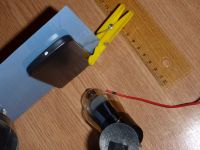
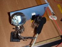
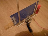
Note: A 2X2 Tube in inverse polarization at 50KV. Setup looks like this:
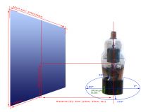
Test1: The Z(vertical) axis:
Here is the last image again, with exposure/brightness increased in software:
Conclusion: As expected, on the vertical axis, the radiation is higher at the same level the anode is (the tungsten filament, under the bell). The bell doesn't make any difference, in fact the radiation is higher where the bell is (it passes straight through).
Test 2: First 360° (X/Y) distribution results
The same setup was used and four images of the fluorescent screen where taken with tube at A=0° , A=90°, A=180°, A=270°. Distance from the tube was D=6 cm (another test with D=10cm was performed, but with the same results).
It was very important not to move the camera at all , not to change any distances, fluorescent screen position, etc, so the results would be comparable. Here are the 4 shots, with exposure/brightness improvement:
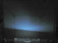
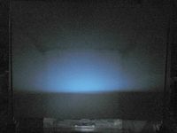
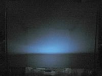
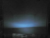
And after Segmentation Threshold was applied (Level=140):
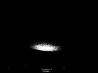
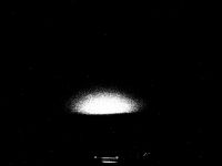
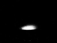

Here's is the tube, at 0°,90°,180°,270° in the same positions used to generate the images above:
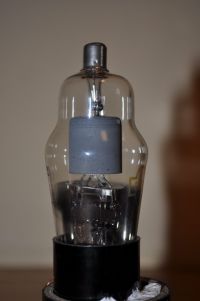
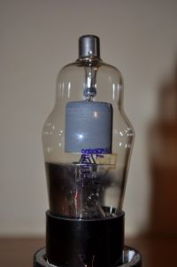
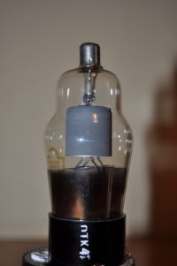
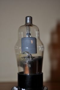
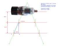
Conclusions:The field distribution is uniform. The small changes in shape are only caused by the small metal plate, under the bell (easily visible by comparing the tube images with the blue fluorescent images). The source of radiation resulting from the 2X2 tube, should be visualized as a HOT, vertical rod, places inside the Bell. This rod, is , of course, the tungsten filament positioned vertically. The metallic bell produces almost no perturbation on the x-ray escaping it, however the small metal plate, under the bell is a strong blocker (it is not steel! what metal could that be?)
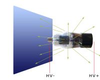
LE: the reason we get less radiation under the bell level is not entirely related to the small metallic plate, but also to the electric field distribution that causes the X-ray emissions: The electrons move from the bell to the inner tungsten filament, and produce x-rays, so we only get them between the bell and the internal filament. The metallic plate only blocks/attenuates a small ammount of rays that are oriented to the bottom of the tube. Most of them however are emitted perpendicular on the filament direction. X-RAY emission is therefore distributed like this:
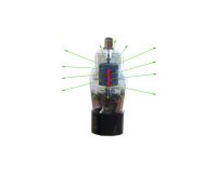
The blue arrows are the electron paths, and the greens are the photons emitted. The internal filament represented in red is connected to HV+ and the external bell is connected to HV-.
Test 3: Another approach to 360° (X/Y) field distribution verification
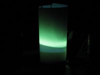
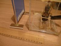
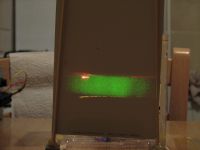
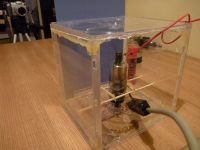
A simpler test was performed, by surrounding the 2X2 with a tube made out of fluorescent material. Some extra attention was payed to keeping the 2X2 as close a possible to the center of the outer tube:

Segmentation on the fluorescent screen images:



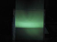
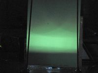
A very nice cylindrical,uniform emission field! The projected band appears to be quite narrow, related to the size of the vertical tungsten filament inside the tube. The picture to the right was added to observe the position of the tube elements as compared to the fluorescence projected on the intensifier screen.
This nice emission field can be used to project good quality radiographs, using this very cheap vacuum tube - the 2X2 .
The only concern is that the emission is radial (cylindrical shape with the center in the tungsten filament) but with some geometry knowledge unaltered, flat projections, can be obtained.
radhoo, Wed Jan 19 2011, 11:22AM
06.A Field distribution test
Note: A 2X2 Tube in inverse polarization at 50KV. Setup looks like this:

Test1: The Z(vertical) axis:


Here is the last image again, with exposure/brightness increased in software:

Conclusion: As expected, on the vertical axis, the radiation is higher at the same level the anode is (the tungsten filament, under the bell). The bell doesn't make any difference, in fact the radiation is higher where the bell is (it passes straight through).
Test 2: First 360° (X/Y) distribution results
The same setup was used and four images of the fluorescent screen where taken with tube at A=0° , A=90°, A=180°, A=270°. Distance from the tube was D=6 cm (another test with D=10cm was performed, but with the same results).
It was very important not to move the camera at all , not to change any distances, fluorescent screen position, etc, so the results would be comparable. Here are the 4 shots, with exposure/brightness improvement:


And after Segmentation Threshold was applied (Level=140):


Here's is the tube, at 0°,90°,180°,270° in the same positions used to generate the images above:


Conclusions:The field distribution is uniform. The small changes in shape are only caused by the small metal plate, under the bell (easily visible by comparing the tube images with the blue fluorescent images). The source of radiation resulting from the 2X2 tube, should be visualized as a HOT, vertical rod, places inside the Bell. This rod, is , of course, the tungsten filament positioned vertically. The metallic bell produces almost no perturbation on the x-ray escaping it, however the small metal plate, under the bell is a strong blocker (it is not steel! what metal could that be?)
LE: the reason we get less radiation under the bell level is not entirely related to the small metallic plate, but also to the electric field distribution that causes the X-ray emissions: The electrons move from the bell to the inner tungsten filament, and produce x-rays, so we only get them between the bell and the internal filament. The metallic plate only blocks/attenuates a small ammount of rays that are oriented to the bottom of the tube. Most of them however are emitted perpendicular on the filament direction. X-RAY emission is therefore distributed like this:

The blue arrows are the electron paths, and the greens are the photons emitted. The internal filament represented in red is connected to HV+ and the external bell is connected to HV-.
Test 3: Another approach to 360° (X/Y) field distribution verification
A simpler test was performed, by surrounding the 2X2 with a tube made out of fluorescent material. Some extra attention was payed to keeping the 2X2 as close a possible to the center of the outer tube:


Segmentation on the fluorescent screen images:


A very nice cylindrical,uniform emission field! The projected band appears to be quite narrow, related to the size of the vertical tungsten filament inside the tube. The picture to the right was added to observe the position of the tube elements as compared to the fluorescence projected on the intensifier screen.
This nice emission field can be used to project good quality radiographs, using this very cheap vacuum tube - the 2X2 .
The only concern is that the emission is radial (cylindrical shape with the center in the tungsten filament) but with some geometry knowledge unaltered, flat projections, can be obtained.
Re: Vacuum Rectifiers X-rays report
Proud Mary, Wed Jan 19 2011, 11:24AM
X-ray production efficiency is roughly kV x Z x 10E-6, where Z is the Atomic Number - 74 in the case of W.
For an anode voltage less than 69.5 kV, there can be no K-characteristic radiation from a tungsten target, as the incident electron energy must exceed the K-shell binding energy for emission to occur.

This paper contains some very interesting observations on W target emission:
Soole BW The Attenuation of X-Radiation Generated at Constant Potentials Sufficient to Excite K-Radiation in a Tungsten Target Phys. Med. Biol., 1971, Vol. 16, No. 3, 427-437

But let's not jump to conclusions that the emission comes from W! Certainly the heater filaments will be either W, or a W/Mo alloy, but there are other metals besides in the construction of the valve.
Edit: You were posting yours above, while I was writing this.
You have made a very good job of this Radhu. Excellent!
Proud Mary, Wed Jan 19 2011, 11:24AM
X-ray production efficiency is roughly kV x Z x 10E-6, where Z is the Atomic Number - 74 in the case of W.
For an anode voltage less than 69.5 kV, there can be no K-characteristic radiation from a tungsten target, as the incident electron energy must exceed the K-shell binding energy for emission to occur.

This paper contains some very interesting observations on W target emission:
Soole BW The Attenuation of X-Radiation Generated at Constant Potentials Sufficient to Excite K-Radiation in a Tungsten Target Phys. Med. Biol., 1971, Vol. 16, No. 3, 427-437

But let's not jump to conclusions that the emission comes from W!
 Certainly the heater filaments will be either W, or a W/Mo alloy, but there are other metals besides in the construction of the valve.
 Edit: You were posting yours above, while I was writing this.
You have made a very good job of this Radhu. Excellent!
Re: Vacuum Rectifiers X-rays report
radhoo, Wed Jan 19 2011, 11:39AM
07.Magnetic field influence
Note: A 2X2 Tube in inverse polarization at 50KV. A very strong Neodymium magnet was placed outside the tube, right next to the bell:
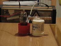
I took three pictures:
1) with the north pole of the magnet set towards the tube
2) without magnet
3) with the south pole of the magnet oriented towards the tube
The results:
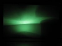
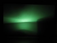
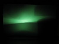
Now the threshold (L=150):



In this setup, the magnet produces no visible influence on the emission field.
I am quite pleased of this method of highlighting the results by using image processing on the fluorescent screen shots. It shows a great potential of observing the x-ray phenomenon in more detail. Segmentation can be binary, as used up until now in my reports, but it can use several threshold levels and multiple colors to indicate various radiation levels. The following example shows two segmentation levels of 180 , corresponding to very intense radiation, and 140, corresponding to a decrease in radiation level:
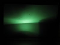

An entire scale of intensities can be built this way with a corresponding color map legend.
radhoo, Wed Jan 19 2011, 11:39AM
07.Magnetic field influence
Note: A 2X2 Tube in inverse polarization at 50KV. A very strong Neodymium magnet was placed outside the tube, right next to the bell:

I took three pictures:
1) with the north pole of the magnet set towards the tube
2) without magnet
3) with the south pole of the magnet oriented towards the tube
The results:


Now the threshold (L=150):


In this setup, the magnet produces no visible influence on the emission field.
I am quite pleased of this method of highlighting the results by using image processing on the fluorescent screen shots. It shows a great potential of observing the x-ray phenomenon in more detail. Segmentation can be binary, as used up until now in my reports, but it can use several threshold levels and multiple colors to indicate various radiation levels. The following example shows two segmentation levels of 180 , corresponding to very intense radiation, and 140, corresponding to a decrease in radiation level:


An entire scale of intensities can be built this way with a corresponding color map legend.
Re: Vacuum Rectifiers X-rays report
Proud Mary, Wed Jan 19 2011, 11:52AM
I feel you should try the magnet experiment again, with the magnets lower down so the magnetic field bisects the open end of the anode bell and the electrode connection leads, where electron field emission is likely to be occurring.
There will be almost no electrons available for interaction with the magnetic field as you show it in the set-up in the picture. The anode bell will shield any electrons flying around inside from the magnetic field.
Re: Vacuum Rectifiers X-rays report
radhoo, Wed Jan 19 2011, 12:00PM
I also need to see the angle at which the narrow emission band expands with distance. This one:
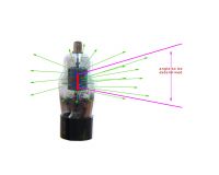
To determine that I will use two fluorescent screen cylinders at a few cm apart.
LE: I will also write a little software to do the segmentation automatically and create a map of colors. If I knew the Fluorescent screen fluorescence coefficient (must be something related to the energy of incident x-ray photon and the amount of visible light emitted), I could link it to the light intensity and compute the x-ray energy of the color map areas.The fluorescence surface would indicate the counts. That would a neat x-ray dosimeter. Eg:
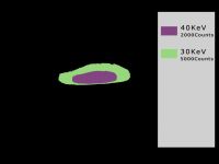
Doing the same thing, but using several camera-captured frames, at a well known time interval, allows the time component to jump in the equation, so the Sv/h can be computed for a given color-map area.
radhoo, Wed Jan 19 2011, 12:00PM
I also need to see the angle at which the narrow emission band expands with distance. This one:

To determine that I will use two fluorescent screen cylinders at a few cm apart.
LE: I will also write a little software to do the segmentation automatically and create a map of colors. If I knew the Fluorescent screen fluorescence coefficient (must be something related to the energy of incident x-ray photon and the amount of visible light emitted), I could link it to the light intensity and compute the x-ray energy of the color map areas.The fluorescence surface would indicate the counts. That would a neat x-ray dosimeter. Eg:

Doing the same thing, but using several camera-captured frames, at a well known time interval, allows the time component to jump in the equation, so the Sv/h can be computed for a given color-map area.
Re: Vacuum Rectifiers X-rays report
Proud Mary, Wed Jan 19 2011, 12:13PM
Radhu, if you use the shadow of a metal washer, you can easily plot the beam divergence, by measuring the amount the washer's circular shadow expands with distance from the valve.
You can also assess the quality of the beam by means of a metal gauze or grill with square holes. Distortion of the squares imaged directly relates to field non-linearity.
Re: Vacuum Rectifiers X-rays report
radhoo, Wed Jan 19 2011, 12:15PM
Indeed, geometry offers endless possibilities to solving a problem.

radhoo, Wed Jan 19 2011, 12:15PM
Indeed, geometry offers endless possibilities to solving a problem.

Re: Vacuum Rectifiers X-rays report
Proud Mary, Wed Jan 19 2011, 12:22PM
I added this to my post above whilst you were posting yours:
You can also assess the quality of the beam by means of a metal gauze or grill with square holes. Distortion of the imaged squares directly relates to field non-linearity.
Proud Mary, Wed Jan 19 2011, 12:22PM
I added this to my post above whilst you were posting yours:
You can also assess the quality of the beam by means of a metal gauze or grill with square holes. Distortion of the imaged squares directly relates to field non-linearity.
Re: Vacuum Rectifiers X-rays report
radhoo, Thu Jan 20 2011, 11:13PM
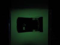
Unfortunately I couldn't find such a metal piece with square holes. I'll see if I find something else. Some more interesting finds are to follow, meanwhile, here are some radiographs I took:
SDCard:
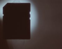

Mogo Bluetooth mouse ( it has a metallic side):
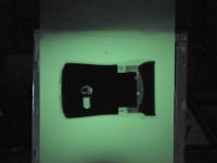
A piece of coral - blocks the rays completely!
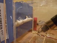
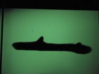
The Kvarts DRSB-01 Dosimeter
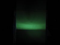
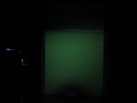
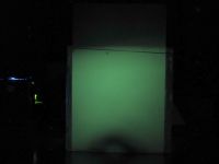
As can be seen in the pictures, the optimal position of the tube is at 45 degrees, with the anode towards the fluorescent screen. This way a maximum uniform illumination surface is obtained (see the nice big square green glow with uniform intensity - less shadows). More on this in the next post.
radhoo, Thu Jan 20 2011, 11:13PM
Unfortunately I couldn't find such a metal piece with square holes. I'll see if I find something else. Some more interesting finds are to follow, meanwhile, here are some radiographs I took:
SDCard:


Mogo Bluetooth mouse ( it has a metallic side):


A piece of coral - blocks the rays completely!


The Kvarts DRSB-01 Dosimeter


As can be seen in the pictures, the optimal position of the tube is at 45 degrees, with the anode towards the fluorescent screen. This way a maximum uniform illumination surface is obtained (see the nice big square green glow with uniform intensity - less shadows). More on this in the next post.
Re: Vacuum Rectifiers X-rays report
Proud Mary, Fri Jan 21 2011, 10:11AM
The random star-like points of light are probably direct X-ray photon strikes on the CCD pixels.
The optimized tube angle suggests to me that the sharp edge of the anode bell is the source of field emission electrons which are impacting on the circular screening plate - though probably there are multiple sources of X-ray emission, some larger than others.
You can image the source directly with an X-ray pinhole camera, but I'd guess that your source is too weak to produce an image in this way
You may be able to improve resolution by means of a hole in a metal plate between the tube and the screen. You could try a hole of 10mm placed directly on the tube glass to start with.
Two or more holes spaced apart would make the simplest form of X-ray collimator.
Re: Vacuum Rectifiers X-rays report
radhoo, Fri Jan 21 2011, 11:29AM
08.Soft vs. Hard X-rays
Note: A 2X2 Tube in inverse polarization at 50KV. At 6cm a green fluorescent screen, with and without aluminum sheet shield.
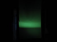
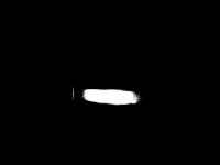
Left picture: Fluorescent screen with Al sheet shield. Right picture: Threshold L=100
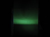
Left picture: Fluorescent screen without any shield. Right picture: Threshold L=100
Conclusion: the amount of soft x-rays seems to be negligible as compared to the hard x-rays. Possible causes: the tube's glass envelope as a blocker -or- the fluorescence produced by the soft-xrays is overwhelmed by the stronger, more intense hard-xray fluorescence.
radhoo, Fri Jan 21 2011, 11:29AM
08.Soft vs. Hard X-rays
Note: A 2X2 Tube in inverse polarization at 50KV. At 6cm a green fluorescent screen, with and without aluminum sheet shield.


Left picture: Fluorescent screen with Al sheet shield. Right picture: Threshold L=100


Left picture: Fluorescent screen without any shield. Right picture: Threshold L=100
Conclusion: the amount of soft x-rays seems to be negligible as compared to the hard x-rays. Possible causes: the tube's glass envelope as a blocker -or- the fluorescence produced by the soft-xrays is overwhelmed by the stronger, more intense hard-xray fluorescence.
Re: Vacuum Rectifiers X-rays report
Proud Mary, Fri Jan 21 2011, 12:01PM
I think you should assume that the glass envelope blocks photons below about 15keV - with possible ranges across 12 - 18keV. So an aluminium filter will not have made much difference.
Expensive lead glass is not likely to have been used in 2X2, which was designed to rectify VRMS 5.5kV max.
The 2X2A iteration was a robust version of 2X2, "for applications critical as to severe shock and vibration" and may have had thicker, more radio-opaque glass, but I am just guessing.
How much the CCCP version followed the US design in glass technology, I have no idea.
Re: Vacuum Rectifiers X-rays report
radhoo, Fri Jan 21 2011, 01:03PM
09.Vertical emission angle
Note: A 2X2 Tube in inverse polarization at 50KV. A fluorescent screen at 6cm and then at 12cm. The tube is positioned vertically, tube's longitudinal axis is parallel to the fluorescent screen plane (see pictures)
Note: The brightness has been increased in software, at 12cm the fluorescence is much fainter than at 6cm.
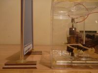
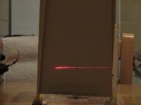
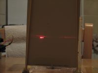
Laser level for bottom and top of 2X2's bell
The measurements:
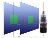
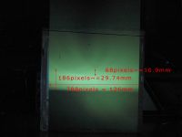
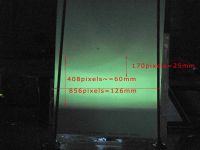
The vertical emission angle is 30°
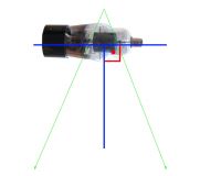
Some excellent news: using the laser level marker and three pictures taken to the same setup (two with laser visible, one with x-ray fluorescence) and software to combine the three images, it can be seen that the vertical's angle bisector is perpendicular on the tube's axis! The origin of the vertical emission angle is at the same height as the center of the bell ( as pictured)
So we got a very well centered / conveniently placed x-ray emission source. Too bad I won't be using it in vertical position. The emission band is too narrow (only 3cm wide at 6 cm away from the tube's center) - good only for tiny objects. See the next post.
radhoo, Fri Jan 21 2011, 01:03PM
09.Vertical emission angle
Note: A 2X2 Tube in inverse polarization at 50KV. A fluorescent screen at 6cm and then at 12cm. The tube is positioned vertically, tube's longitudinal axis is parallel to the fluorescent screen plane (see pictures)


Note: The brightness has been increased in software, at 12cm the fluorescence is much fainter than at 6cm.


Laser level for bottom and top of 2X2's bell
The measurements:


The vertical emission angle is 30°


Some excellent news: using the laser level marker and three pictures taken to the same setup (two with laser visible, one with x-ray fluorescence) and software to combine the three images, it can be seen that the vertical's angle bisector is perpendicular on the tube's axis! The origin of the vertical emission angle is at the same height as the center of the bell ( as pictured)
So we got a very well centered / conveniently placed x-ray emission source. Too bad I won't be using it in vertical position. The emission band is too narrow (only 3cm wide at 6 cm away from the tube's center) - good only for tiny objects. See the next post.
Re: Vacuum Rectifiers X-rays report
radhoo, Fri Jan 21 2011, 01:10PM
radhoo, Fri Jan 21 2011, 01:10PM
Proud Mary wrote ...
The random star-like points of light are probably direct X-ray photon strikes on the CCD pixels.
The optimized tube angle suggests to me that the sharp edge of the anode bell is the source of field emission electrons which are impacting on the circular screening plate - though probably there are multiple sources of X-ray emission, some larger than others.
Hard to tell , when the tube is placed in vertical position, there are strong indications that the center of emission is the center of the bell. Very round, nice, numbers.The random star-like points of light are probably direct X-ray photon strikes on the CCD pixels.
The optimized tube angle suggests to me that the sharp edge of the anode bell is the source of field emission electrons which are impacting on the circular screening plate - though probably there are multiple sources of X-ray emission, some larger than others.
Proud Mary wrote ...
You can image the source directly with an X-ray pinhole camera, but I'd guess that your source is too weak to produce an image in this way
You may be able to improve resolution by means of a hole in a metal plate between the tube and the screen. You could try a hole of 10mm placed directly on the tube glass to start with.
Two or more holes spaced apart would make the simplest form of X-ray collimator.
Thanks, I will try that.You can image the source directly with an X-ray pinhole camera, but I'd guess that your source is too weak to produce an image in this way
You may be able to improve resolution by means of a hole in a metal plate between the tube and the screen. You could try a hole of 10mm placed directly on the tube glass to start with.
Two or more holes spaced apart would make the simplest form of X-ray collimator.
Re: Vacuum Rectifiers X-rays report
radhoo, Fri Jan 21 2011, 01:37PM
09.Emission at 45°
Note: A 2X2 Tube in inverse polarization at 50KV. The tube is inclined, tube's longitudinal axis makes a 45° angle to the fluorescent screen plane (see pictures)
I already uploaded a few radiographs, underlining that the best position in terms of x-ray illuminated surface, but also uniformity of the filed intensity, is when placing the tube at 45°. As a comparison, here are two pictures, one with the tube in vertical stand, and the second with the tube at 45° (the pictures are not altered in software, they are as recorded by the camera):
To compare emission intensity, here are the images again, with Threshold (L=50) applied in software:
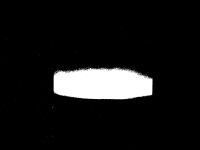
Placing the tube in vertical position offers a very good, strong emission, unfortunately the illuminated surface comes as a narrow band of only 3cm at 6cm away from the tube. On the other hand, placing the tube inclined at 45°, results in a sport-like surface, better suited for illuminating various objects. The only loss is x-ray intensity, but we still have sufficient levels for taking radiographs.
Another big advantage of placing the tube at 45° is the uniformity of the emission: not yet understood why, but I got sharper images with less shadows this way. Here is a comparison:
The first object is a DY86 tube. The emission tube 2x2 was placed in vertical stand.
The second radiograph shows several objects (SDCard, USB Flash, USB WLAN). The tube was placed at 45°.
Comments:
The first radiograph shows blurry edges and shadows. On the other hand, the second radiograph shows very sharp edges, with no shadows.
This uniformity can also be observed in the green fluorescence color - the second picture clearly comes with a smoother, more homogeneous green color - an advantage clearly reflected in the quality of the radiographs.
Pictures of the setup:
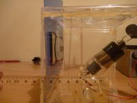
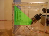
Notice the emission pictured in the last image. The bottom level corresponds to the bell position, while the upper level limit is projected by the small metal plate, under the bell. Rotating the tube produces different top projections, because of the position of the small metal plate (not quite parallel to the bell's bottom surface):
radhoo, Fri Jan 21 2011, 01:37PM
09.Emission at 45°
Note: A 2X2 Tube in inverse polarization at 50KV. The tube is inclined, tube's longitudinal axis makes a 45° angle to the fluorescent screen plane (see pictures)
I already uploaded a few radiographs, underlining that the best position in terms of x-ray illuminated surface, but also uniformity of the filed intensity, is when placing the tube at 45°. As a comparison, here are two pictures, one with the tube in vertical stand, and the second with the tube at 45° (the pictures are not altered in software, they are as recorded by the camera):


To compare emission intensity, here are the images again, with Threshold (L=50) applied in software:


Placing the tube in vertical position offers a very good, strong emission, unfortunately the illuminated surface comes as a narrow band of only 3cm at 6cm away from the tube. On the other hand, placing the tube inclined at 45°, results in a sport-like surface, better suited for illuminating various objects. The only loss is x-ray intensity, but we still have sufficient levels for taking radiographs.
Another big advantage of placing the tube at 45° is the uniformity of the emission: not yet understood why, but I got sharper images with less shadows this way. Here is a comparison:


The first object is a DY86 tube. The emission tube 2x2 was placed in vertical stand.
The second radiograph shows several objects (SDCard, USB Flash, USB WLAN). The tube was placed at 45°.
Comments:
The first radiograph shows blurry edges and shadows. On the other hand, the second radiograph shows very sharp edges, with no shadows.
This uniformity can also be observed in the green fluorescence color - the second picture clearly comes with a smoother, more homogeneous green color - an advantage clearly reflected in the quality of the radiographs.
Pictures of the setup:


Notice the emission pictured in the last image. The bottom level corresponds to the bell position, while the upper level limit is projected by the small metal plate, under the bell. Rotating the tube produces different top projections, because of the position of the small metal plate (not quite parallel to the bell's bottom surface):


Re: Vacuum Rectifiers X-rays report
radhoo, Fri Jan 21 2011, 01:49PM
10.Other vacuum tubes
Note: I will be using several vacuum rectifier tubes or shunts, in inverse polarization at 50KV.
DY86:
Weak, or no emission.
Three other high voltage tubes 3A3, 3CZ3, 6LJ6:
No emission . These 3 tubes all come with lead-glass.
So bottom line is 2X2 is a great tube, both affordable and producing nice amounts of x-rays. Thanks to Proud Mary for the discovery:
radhoo, Fri Jan 21 2011, 01:49PM
10.Other vacuum tubes
Note: I will be using several vacuum rectifier tubes or shunts, in inverse polarization at 50KV.
DY86:


Weak, or no emission.
Three other high voltage tubes 3A3, 3CZ3, 6LJ6:


No emission . These 3 tubes all come with lead-glass.
So bottom line is 2X2 is a great tube, both affordable and producing nice amounts of x-rays. Thanks to Proud Mary for the discovery:

Re: Vacuum Rectifiers X-rays report
radhoo, Fri Jan 21 2011, 02:00PM
Some more images:
A remote control with blue and green fluorescent screen . I prefer the green (Kodak lanex fine):
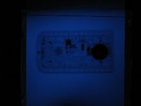
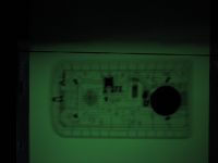
A TV Cascade multiplier and a SD Card (from my first tests - not the best photo)
Another type of TV Cascade multiplier
In case anyone wants me to test the 2X2 with a particular target, just drop a few lines.
radhoo, Fri Jan 21 2011, 02:00PM
Some more images:
A remote control with blue and green fluorescent screen . I prefer the green (Kodak lanex fine):


A TV Cascade multiplier and a SD Card (from my first tests - not the best photo)

Another type of TV Cascade multiplier

In case anyone wants me to test the 2X2 with a particular target, just drop a few lines.
Re: Vacuum Rectifiers X-rays report
Proud Mary, Fri Jan 21 2011, 02:19PM
Have you any minerals or crystals to test for fluorescence, Radhu?
And not forgetting your NaI(Tl) scintillator block.
Proud Mary, Fri Jan 21 2011, 02:19PM
Have you any minerals or crystals to test for fluorescence, Radhu?
And not forgetting your NaI(Tl) scintillator block.
Re: Vacuum Rectifiers X-rays report
radhoo, Fri Jan 21 2011, 02:55PM
I'll be testing the scintillator soon.
radhoo, Fri Jan 21 2011, 02:55PM
Proud Mary wrote ...
Have you any minerals or crystals to test for fluorescence, Radhu?
And not forgetting your NaI(Tl) scintillator block.
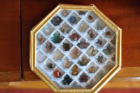
I got a few, from a mine near Antsirabe, Madagascar:Have you any minerals or crystals to test for fluorescence, Radhu?
And not forgetting your NaI(Tl) scintillator block.

I'll be testing the scintillator soon.
Re: Vacuum Rectifiers X-rays report
Proud Mary, Fri Jan 21 2011, 03:04PM
Ah, the benefits of a wide interest in general science!
Some of those mineral specimens are sure to fluoresce.
Proud Mary, Fri Jan 21 2011, 03:04PM
Ah, the benefits of a wide interest in general science!

Some of those mineral specimens are sure to fluoresce.
Re: Vacuum Rectifiers X-rays report
Proud Mary, Fri Jan 21 2011, 05:40PM
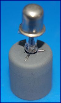
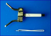
Radhu, I found a box of 2X2As under the stairs, so have sacrificed one to get a decent image of the cathode assembly for you. Comparing this with your angle plot, the rays may well be coming from the oxide cathode.
The misalignment of the cathode occurred while breaking the glass.

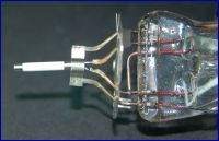
The anode bell is strongly attracted to a magnet - perhaps a nickel alloy. The screening disk is also magnetic.
EDIT: I've thought about what I have called a 'screening disk' and now think it is a heat shield to protect the glass seals from radiant heat.
In an amplifier, one would think of it being an EMI shield, but not in a diode power rectifier like 2X2. The bright reflective surface of the disk supports this interpretation.
Proud Mary, Fri Jan 21 2011, 05:40PM
Radhu, I found a box of 2X2As under the stairs, so have sacrificed one to get a decent image of the cathode assembly for you. Comparing this with your angle plot, the rays may well be coming from the oxide cathode.
The misalignment of the cathode occurred while breaking the glass.


The anode bell is strongly attracted to a magnet - perhaps a nickel alloy. The screening disk is also magnetic.
EDIT: I've thought about what I have called a 'screening disk' and now think it is a heat shield to protect the glass seals from radiant heat.
In an amplifier, one would think of it being an EMI shield, but not in a diode power rectifier like 2X2. The bright reflective surface of the disk supports this interpretation.
Re: Vacuum Rectifiers X-rays report
radhoo, Tue Jan 25 2011, 12:47PM
Well, one way or another, that disk is making the lower part of the x-ray emitting 2X2 useless. But even so, this tube is great.
Thanks for sharing those nice pictures. Here is one with the tube in operation, showing the hot, glowing "cathode" caused by electron bombardment (that sounded very SciFi-ish):
I had little luck with my minerals, I tried a different pack containing mostly quartz based stones, polished nicely in sphere shapes, but will try the one posted above as well:
radhoo, Tue Jan 25 2011, 12:47PM
Well, one way or another, that disk is making the lower part of the x-ray emitting 2X2 useless. But even so, this tube is great.
Thanks for sharing those nice pictures. Here is one with the tube in operation, showing the hot, glowing "cathode" caused by electron bombardment (that sounded very SciFi-ish):


I had little luck with my minerals, I tried a different pack containing mostly quartz based stones, polished nicely in sphere shapes, but will try the one posted above as well:

Re: Vacuum Rectifiers X-rays report
radhoo, Tue Jan 25 2011, 12:51PM
and while the tube is glowing inside , here are some outside results:

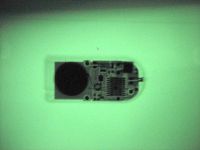
First picture: an audio system IR remote while illuminated by the 2X2 tube
Second picture: a hardware password key
Third: a camera IR remote
I might be able to increase the voltage even further, and run some other tests, if I make a lead box first:
radhoo, Tue Jan 25 2011, 12:51PM
and while the tube is glowing inside , here are some outside results:


First picture: an audio system IR remote while illuminated by the 2X2 tube
Second picture: a hardware password key
Third: a camera IR remote
I might be able to increase the voltage even further, and run some other tests, if I make a lead box first:

Re: Vacuum Rectifiers X-rays report
Proud Mary, Tue Jan 25 2011, 02:44PM
Did you think to wonder when in history the lead shielding Recommendations of the Second International Congress of Radiology were made, Radu?
You can read all about it in the crumbling, yellowed pages of The British Journal of Radiology (1928) 1, 30
I am not saying it is necessarily wrong, but that data of such vintage must be carefully evaluated before putting it to any practical purpose. For example, no duration of exposure is given, a serious omission. Standards of radiological protection have changed dramatically for the better in the last eighty years.
There is an on-line X-ray shielding calculator for lead and other common materials run by the University of Dundee here:
There is a Constant Potential X-Ray Device Dose-Rate and Shielding Calculator at the RadPro site here:
and a dose-rate/distance Inverse Square Law calculator here:
Edit: Afterword on Fluorescent Minerals
Minerals which fluoresce with short wave UV will often fluoresce with X-rays.
This table distinguishes between short wave and long wave UV induced fluorescence:
Mineral UV Fluorescence Colors - Summary Chart is here:
Proud Mary, Tue Jan 25 2011, 02:44PM
radhoo wrote ...
I might be able to increase the voltage even further, and run some other tests, if I make a lead box first:
I might be able to increase the voltage even further, and run some other tests, if I make a lead box first:

Did you think to wonder when in history the lead shielding Recommendations of the Second International Congress of Radiology were made, Radu?
You can read all about it in the crumbling, yellowed pages of The British Journal of Radiology (1928) 1, 30

I am not saying it is necessarily wrong, but that data of such vintage must be carefully evaluated before putting it to any practical purpose. For example, no duration of exposure is given, a serious omission. Standards of radiological protection have changed dramatically for the better in the last eighty years.
There is an on-line X-ray shielding calculator for lead and other common materials run by the University of Dundee here:

There is a Constant Potential X-Ray Device Dose-Rate and Shielding Calculator at the RadPro site here:

and a dose-rate/distance Inverse Square Law calculator here:

Edit: Afterword on Fluorescent Minerals
Minerals which fluoresce with short wave UV will often fluoresce with X-rays.
This table distinguishes between short wave and long wave UV induced fluorescence:
Mineral UV Fluorescence Colors - Summary Chart is here:

Re: Vacuum Rectifiers X-rays report
radhoo, Tue Jan 25 2011, 06:42PM
I will try some uranium glass that puts out a very strong greenish fluorescence under UV light, making sure I block all visible/UV light from the tube with a piece of aluminum foil.
radhoo, Tue Jan 25 2011, 06:42PM
I will try some uranium glass that puts out a very strong greenish fluorescence under UV light, making sure I block all visible/UV light from the tube with a piece of aluminum foil.
Re: Vacuum Rectifiers X-rays report
Proud Mary, Tue Jan 25 2011, 07:11PM
Black card, and heavy black paper of the type called 'cartridge paper,' can be bought from artists' materials shops, and are both very useful in this sort of work. For extra light-proofing, you can use kitchen aluminium foil on the outside, and the black paper inside to reduce reflection of any light leakage left. It is worthwhile having double layers like this in photon counting experiments with photomultipliers.
Softer X-rays may not be able to penetrate the outer layer of a sample, and so produce little fluorescence even when the substance itself is in fact quite fluorescent.
The glow discharge in the 2X2 looks very interesting. When I did my 2X2 experiments, I didn't give it much thought, as I knew much less than I know now. What is it? I don't have an optical spectrometer, and don't fancy trying to use the home made DVD-type spectrometer near an X-ray source. But I have a hunch that the explanation for the plentiful X-ray emission of 2X2 compared with other popular X-ray sources - PD500, 6BK4B etc - will be found in a spectral analysis of the glow discharge.
Proud Mary, Tue Jan 25 2011, 07:11PM
radhoo wrote ...
I will try some uranium glass that puts out a very strong greenish fluorescence under UV light, making sure I block all visible/UV light from the tube with a piece of aluminum foil.
I will try some uranium glass that puts out a very strong greenish fluorescence under UV light, making sure I block all visible/UV light from the tube with a piece of aluminum foil.
Black card, and heavy black paper of the type called 'cartridge paper,' can be bought from artists' materials shops, and are both very useful in this sort of work. For extra light-proofing, you can use kitchen aluminium foil on the outside, and the black paper inside to reduce reflection of any light leakage left. It is worthwhile having double layers like this in photon counting experiments with photomultipliers.
Softer X-rays may not be able to penetrate the outer layer of a sample, and so produce little fluorescence even when the substance itself is in fact quite fluorescent.
The glow discharge in the 2X2 looks very interesting. When I did my 2X2 experiments, I didn't give it much thought, as I knew much less than I know now. What is it? I don't have an optical spectrometer, and don't fancy trying to use the home made DVD-type spectrometer near an X-ray source. But I have a hunch that the explanation for the plentiful X-ray emission of 2X2 compared with other popular X-ray sources - PD500, 6BK4B etc - will be found in a spectral analysis of the glow discharge.
Re: Vacuum Rectifiers X-rays report
radhoo, Wed Jan 26 2011, 11:39AM
I'd say that the first difference between the 2X2 and shunts like PD500, 6BK4B but also 6LJ6A etc, is the target geometry/position.
Instead of having a bottom, small sized filament, the 2X2 comes with an inner, rod like, central / very conveniently placed filament, covered in that white oxide that seems to help a lot - I believe the following features result from this:
- uniform emission with less shadows, when placing the tube at 45degrees the resulting images are well illuminated
- no electron beam focal points that would melt/puncture the filament if it was to be struck directly
I will capture a few close-up pictures of this glow, next time I power the tube. Now that the winter is so harsh I have other electron related problems - making my diesel car start.
Re: Vacuum Rectifiers X-rays report
Proud Mary, Wed Jan 26 2011, 01:32PM
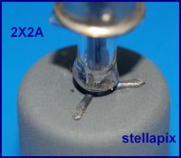
The external diameter of the anode bell is 20mm.
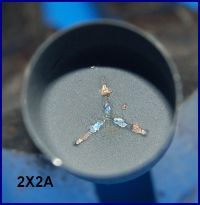
The very slightly elevated and rough spot welds on the inside top of the anode are a possible field emission source.
Proud Mary, Wed Jan 26 2011, 01:32PM

The external diameter of the anode bell is 20mm.


The very slightly elevated and rough spot welds on the inside top of the anode are a possible field emission source.
Re: Vacuum Rectifiers X-rays report
radhoo, Wed Jan 26 2011, 03:14PM
Great pictures.
Does it make sense to find out the anode bell's density?
With a sensitive balance the weight should be no problem. I'm not so sure about the volume, using a liquid and a small graduated container - might require cutting the anode bell in small pieces to fit a small tube. For bigger tubes would be hard to distinguish the levels difference.
That's a fair assumption. But shouldn't that limit the area of the new cathode that gets the electron bombardment? In a picture I took with a different purpose (posted abovE) the internal oxide rod glows intensely. Having such a tiny electron emitters I would have expected to see only the top part of the oxide rod glowing.
What happens under high vacuum anyway: Do electron jump on the shortest path, or there is a diffuse electrical field filling the space between electrodes?
radhoo, Wed Jan 26 2011, 03:14PM
Great pictures.
Does it make sense to find out the anode bell's density?
With a sensitive balance the weight should be no problem. I'm not so sure about the volume, using a liquid and a small graduated container - might require cutting the anode bell in small pieces to fit a small tube. For bigger tubes would be hard to distinguish the levels difference.
Proud Mary wrote ...
The very slightly elevated and rough spot welds on the inside top of the anode are a possible field emission source.
The very slightly elevated and rough spot welds on the inside top of the anode are a possible field emission source.
That's a fair assumption. But shouldn't that limit the area of the new cathode that gets the electron bombardment? In a picture I took with a different purpose (posted abovE) the internal oxide rod glows intensely. Having such a tiny electron emitters I would have expected to see only the top part of the oxide rod glowing.
What happens under high vacuum anyway: Do electron jump on the shortest path, or there is a diffuse electrical field filling the space between electrodes?
Re: Vacuum Rectifiers X-rays report
Proud Mary, Wed Jan 26 2011, 05:07PM
According to Lederer,* cathode oxide coatings consist of mixtures of any of barium, strontium, calcium, and zinc, with mixtures of barium and strontium oxides being by far the most common.
A glance at the characteristic spectra of these four elements suggests that with Va = 40kV only a barium-containing target will emit X-rays energetic enough to escape through the anode bell and the glass envelope. Increasing the anode voltage from c. 38kV to c. 55kV will increase the output fluence of the barium target - the quantity of rays - but will not increase their penetrating power at all. Increasing Va to 65kV will produce little significant increase in penetration, as the graph makes clear. But the extra energy imparted to the electrons will be dissipated as heat in the fragile barium target, and very likely ruin it.

Strontium target: feeble bremmstrahlung and main peak below 15keV

Calcium target: assorted weak peaks over 20keV - a possible contender, but not very likely.

Zn target: feeble bremmstrahlung and peak below 10keV.

Now if you were to gradually reduce the tube voltage to 30kV, if there was a sudden fall in X-ray output once those Ba peaks are past, it would support the barium hypothesis.
The light source may be due to incandescence, as of calcium limelight.
Field Emission is a type of quantum tunneling which occurs at points of very high charge density - as in the needle and flat plate type of cold cathode X-ray source. The needle model goes right down to the nano-scale, with field emission cathodes made of carbon nanotubes now being used in sub-miniature X-ray sources the size of a grain of rice.
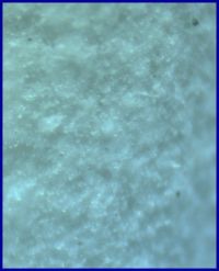
This macro image shows a number of sharp points on the anode spot weld:
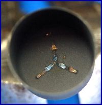
Notice strong shadows of the weld spikes in upper right quadrant of photomicrograph below:
x40 new
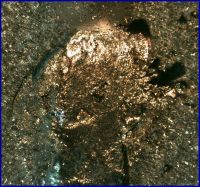
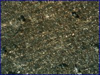
Here are photomicrographs of the anode bell coating at x80 and x200.
x80. Notice volcanic crater with three gas vents in the upper left quadrant. Also diagonal fissure below it. [color]re-done
x200
Note gold-coloured inclusions of unknown significance new
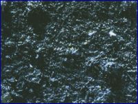
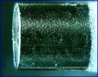
Cathode oxide coat x400 showing unknown inclusions - presumably manufacturing contamination.
The cathode tube, and its supports, are made of a magnetic metal. The damage to the oxide coat was done by Spencer-Wells forceps.
Cathode bare metal tip
x40.
The tungsten-molybdenum alloy heater is insulated with either aluminium oxide - aluminia - or beryllium oxide - beryllia - HAZARD! - but may contain small quantities of other refractory materials necessary to the coating process.* The 2X2As folded heater design was simpler and less expensive to produce than the double helix kind. The rust-coloured markings suggest the presence of iron.
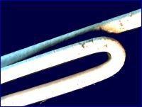
x40
* Shaw GR, Shardlow LR, Heaters & Heater-Cathode Insulation, Vacuum Tube Design, RCA, Privately Printed, 1940, p. 24 et seq.
*Lederer, LE, Filaments and Cathodes Part II, Lecture 2, Vacuum Tube Design, p.11 et seq. Privately printed, RCA, 1940.
Proud Mary, Wed Jan 26 2011, 05:07PM
According to Lederer,* cathode oxide coatings consist of mixtures of any of barium, strontium, calcium, and zinc, with mixtures of barium and strontium oxides being by far the most common.
A glance at the characteristic spectra of these four elements suggests that with Va = 40kV only a barium-containing target will emit X-rays energetic enough to escape through the anode bell and the glass envelope. Increasing the anode voltage from c. 38kV to c. 55kV will increase the output fluence of the barium target - the quantity of rays - but will not increase their penetrating power at all. Increasing Va to 65kV will produce little significant increase in penetration, as the graph makes clear. But the extra energy imparted to the electrons will be dissipated as heat in the fragile barium target, and very likely ruin it.

Strontium target: feeble bremmstrahlung and main peak below 15keV

Calcium target: assorted weak peaks over 20keV - a possible contender, but not very likely.

Zn target: feeble bremmstrahlung and peak below 10keV.

Now if you were to gradually reduce the tube voltage to 30kV, if there was a sudden fall in X-ray output once those Ba peaks are past, it would support the barium hypothesis.
The light source may be due to incandescence, as of calcium limelight.
Field Emission is a type of quantum tunneling which occurs at points of very high charge density - as in the needle and flat plate type of cold cathode X-ray source. The needle model goes right down to the nano-scale, with field emission cathodes made of carbon nanotubes now being used in sub-miniature X-ray sources the size of a grain of rice.
This macro image shows a number of sharp points on the anode spot weld:

Notice strong shadows of the weld spikes in upper right quadrant of photomicrograph below:

x40 new
Here are photomicrographs of the anode bell coating at x80 and x200.

x80. Notice volcanic crater with three gas vents in the upper left quadrant. Also diagonal fissure below it. [color]re-done

x200
Note gold-coloured inclusions of unknown significance new

Cathode oxide coat x400 showing unknown inclusions - presumably manufacturing contamination.
The cathode tube, and its supports, are made of a magnetic metal. The damage to the oxide coat was done by Spencer-Wells forceps.

Cathode bare metal tip

x40.
The tungsten-molybdenum alloy heater is insulated with either aluminium oxide - aluminia - or beryllium oxide - beryllia - HAZARD! - but may contain small quantities of other refractory materials necessary to the coating process.* The 2X2As folded heater design was simpler and less expensive to produce than the double helix kind. The rust-coloured markings suggest the presence of iron.

x40
* Shaw GR, Shardlow LR, Heaters & Heater-Cathode Insulation, Vacuum Tube Design, RCA, Privately Printed, 1940, p. 24 et seq.
*Lederer, LE, Filaments and Cathodes Part II, Lecture 2, Vacuum Tube Design, p.11 et seq. Privately printed, RCA, 1940.
Re: Vacuum Rectifiers X-rays report
radhoo, Fri Jan 28 2011, 09:24AM
do you have a microscope adapter for your SLR?
LE: I might break a tube myself, to try to identify the barium ion using diluted sulfuric acid, when a white precipitate should appear.
radhoo, Fri Jan 28 2011, 09:24AM
do you have a microscope adapter for your SLR?
LE: I might break a tube myself, to try to identify the barium ion using diluted sulfuric acid, when a white precipitate should appear.
Re: Vacuum Rectifiers X-rays report
Proud Mary, Fri Jan 28 2011, 09:50AM
I do have a microscope adapter for my DSLR, but didn't use it for the photomicrographs above, which I took using a 3MP digital eyepiece adapter in a Vickers metallurgical microscope.
Looking at the images in the cold light of day, I can see all their faults, and will replace them one by one with examples of better quality, when I can find the time. I am marking re-done and new images as "redone" and "new" in red.
LE: My own knowledge of chemistry goes little further than mixing up powders to keep slugs out of the cabbages, so I wish you luck with this chemical analysis. But I completely agree that we should try to find a verifiable explanation for 2X2's superior performance compared with PD500, 6BK4B etc.
Proud Mary, Fri Jan 28 2011, 09:50AM
radhoo wrote ...
do you have a microscope adapter for your SLR?
do you have a microscope adapter for your SLR?
I do have a microscope adapter for my DSLR, but didn't use it for the photomicrographs above, which I took using a 3MP digital eyepiece adapter in a Vickers metallurgical microscope.
Looking at the images in the cold light of day, I can see all their faults, and will replace them one by one with examples of better quality, when I can find the time. I am marking re-done and new images as "redone" and "new" in red.
LE: My own knowledge of chemistry goes little further than mixing up powders to keep slugs out of the cabbages, so I wish you luck with this chemical analysis. But I completely agree that we should try to find a verifiable explanation for 2X2's superior performance compared with PD500, 6BK4B etc.
Re: Vacuum Rectifiers X-rays report
Steve Conner, Fri Jan 28 2011, 12:09PM
A very interesting project! :)
The pinhole camera might be worth a try. The "camera" of course is simply a lead sheet with a small hole poked in it. The instructions I saw for making it were to bash an indent in the sheet with a hammer and punch, then cut/file off the little bump that appears on the other side.
From looking at your results, the tube seems to have two point sources inside it. It would be interesting to get a pinhole camera picture of them.
I think the dark ring discussed earlier can be explained by the variation in thickness of the anode bell normal to the direction of the X-rays.
Re: Vacuum Rectifiers X-rays report
Adam Munich, Fri Jan 28 2011, 01:47PM
I'm very impressed with all this testing. You should put this info somewhere on the open interwebs, and not in the for the most part unsearchable depths of this forum.
Adam Munich, Fri Jan 28 2011, 01:47PM
I'm very impressed with all this testing. You should put this info somewhere on the open interwebs, and not in the for the most part unsearchable depths of this forum.
Re: Vacuum Rectifiers X-rays report
Proud Mary, Fri Jan 28 2011, 06:54PM
It's one thing to use a pinhole to image the anode spot of, for example only, a dental tube 70kV/7mA with a dose-rate of 1.5E+004 Sv/hr across the entrance to a pinhole 3cm from the target, (of which, say, 0.1% transits the pinhole) and another to form an image with the tiny fluence of a 2X2A in cold cathode mode and a few tens of microamps of current @40kV. Moreover, a dental tube's roughly conical beam is highly directional, while Radu's experiments suggest that the 2X2A output tends towards the isotropic, with only a small part of its X-ray output available for image formation on a plane surface.
As to the dark ring, I first thought the same as you - that it was the shadow of the anode wall cast by a source coaxial with, and below, the anode bell, but Radu's subsequent experiments suggest a multiple or disseminated locus of emission.
I am now wondering whether a slit formed from two razor blades might be able to form an image from which further deductions could be made.
Proud Mary, Fri Jan 28 2011, 06:54PM
Steve McConner wrote ...
The pinhole camera might be worth a try. The "camera" of course is simply a lead sheet with a small hole poked in it. The instructions I saw for making it were to bash an indent in the sheet with a hammer and punch, then cut/file off the little bump that appears on the other side.
From looking at your results, the tube seems to have two point sources inside it. It would be interesting to get a pinhole camera picture of them.
I think the dark ring discussed earlier can be explained by the variation in thickness of the anode bell normal to the direction of the X-rays.
It's one thing to use a pinhole to image the anode spot of, for example only, a dental tube 70kV/7mA with a dose-rate of 1.5E+004 Sv/hr across the entrance to a pinhole 3cm from the target, (of which, say, 0.1% transits the pinhole) and another to form an image with the tiny fluence of a 2X2A in cold cathode mode and a few tens of microamps of current @40kV. Moreover, a dental tube's roughly conical beam is highly directional, while Radu's experiments suggest that the 2X2A output tends towards the isotropic, with only a small part of its X-ray output available for image formation on a plane surface.
As to the dark ring, I first thought the same as you - that it was the shadow of the anode wall cast by a source coaxial with, and below, the anode bell, but Radu's subsequent experiments suggest a multiple or disseminated locus of emission.
I am now wondering whether a slit formed from two razor blades might be able to form an image from which further deductions could be made.
Re: Vacuum Rectifiers X-rays report
Patrick, Sat Jan 29 2011, 03:57AM
This is a great thread Radhoo!
Patrick, Sat Jan 29 2011, 03:57AM
This is a great thread Radhoo!
Re: Vacuum Rectifiers X-rays report
Proud Mary, Sat Jan 29 2011, 05:58PM
Photomicrographs now amalgamated into post above - please delete this.
Proud Mary, Sat Jan 29 2011, 05:58PM
Photomicrographs now amalgamated into post above - please delete this.
Re: Vacuum Rectifiers X-rays report
Nah, Sat Jan 29 2011, 08:27PM
Try using a 2b21, the "modern" 2x2
Nah, Sat Jan 29 2011, 08:27PM
Try using a 2b21, the "modern" 2x2
Re: Vacuum Rectifiers X-rays report
Patrick, Sat Jan 29 2011, 10:21PM
beryllia salad dressing anyone ?
Patrick, Sat Jan 29 2011, 10:21PM
beryllia salad dressing anyone ?
Re: Vacuum Rectifiers X-rays report
radhoo, Mon Jan 31 2011, 05:33PM
Stella, those are some very nice pictures. I'll get back on this with some more tests an ideas somewhere during this week.
hint: you can use the "preview" option without pressing "Reply", the attachments will get saved, but the message not.
radhoo, Mon Jan 31 2011, 05:33PM
Proud Mary wrote ...
Photomicrographs now amalgamated into post above - please delete this.
Steve, Grenadier, Patrick, Nah thanks!Photomicrographs now amalgamated into post above - please delete this.
Stella, those are some very nice pictures. I'll get back on this with some more tests an ideas somewhere during this week.
hint: you can use the "preview" option without pressing "Reply", the attachments will get saved, but the message not.
Re: Vacuum Rectifiers X-rays report
Nah, Wed Feb 02 2011, 03:40PM
I forgot.
Wonderful work!
I will be sure to be tuned in.
Nah, Wed Feb 02 2011, 03:40PM
I forgot.
Wonderful work!
I will be sure to be tuned in.

Re: Vacuum Rectifiers X-rays report
Proud Mary, Wed Feb 02 2011, 06:57PM
This getter retaining grille is spot welded to the underside of the heat shield, and from an X-ray source perspective suggests the possible existence of additional elements with their own characteristic radiation to add to the output spectrum mix.
The triangle of material missing at right in this macro image of the heat shield was clipped off for destructive testing.
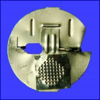
This image at x40 suggests the presence of a once liquid metal on the lips of the perforations.
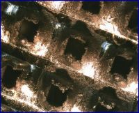
Here at x80 I am still not certain if what we are seeing on the perforation lips is metal that once flowed, or just an artefact of the punch perforation process.
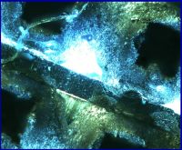
Proud Mary, Wed Feb 02 2011, 06:57PM
This getter retaining grille is spot welded to the underside of the heat shield, and from an X-ray source perspective suggests the possible existence of additional elements with their own characteristic radiation to add to the output spectrum mix.
The triangle of material missing at right in this macro image of the heat shield was clipped off for destructive testing.

This image at x40 suggests the presence of a once liquid metal on the lips of the perforations.

Here at x80 I am still not certain if what we are seeing on the perforation lips is metal that once flowed, or just an artefact of the punch perforation process.

Re: Vacuum Rectifiers X-rays report
Patrick, Thu Feb 03 2011, 06:06AM
In the long long ago, in a Galaxy far away in the San Jose, CA region of the universe, I was a professional NC punch press operator of the Amada Vipros 358, and 558 variety....
What I see in the micrographs looks like chemical artifacts not shearing asssociated with punching, without knowing what the metal composistion is I can't be sure, but I would bet more on there being chemistry (maybe liquid which once flowed) responsible.
Re: Vacuum Rectifiers X-rays report
Proud Mary, Thu Feb 03 2011, 11:49AM
Oi! Paddy! Get back to your own Event Horizon!
As this isn't my thread, I'll just say that I'm planning a few more metallographic experiments in support of Radu's investigation, with greater attention to sample surface preparation, which I hope will clear up the ambiguity in some of these images.
Proud Mary, Thu Feb 03 2011, 11:49AM
Patrick wrote ...
In the long long ago, in a Galaxy far away in the San Jose, CA region of the universe, I was a professional NC punch press operator of the Amada Vipros 358, and 558 variety....
What I see in the micrographs looks like chemical artifacts not shearing asssociated with punching, without knowing what the metal composistion is I can't be sure, but I would bet more on there being chemistry (maybe liquid which once flowed) responsible.
Oi! Paddy! Get back to your own Event Horizon!

As this isn't my thread, I'll just say that I'm planning a few more metallographic experiments in support of Radu's investigation, with greater attention to sample surface preparation, which I hope will clear up the ambiguity in some of these images.
Re: Vacuum Rectifiers X-rays report
radhoo, Fri Feb 11 2011, 07:13PM
radhoo, Fri Feb 11 2011, 07:13PM
Proud Mary wrote ...
As this isn't my thread, I'll just say that I'm planning a few more metallographic experiments in support of Radu's investigation, with greater attention to sample surface preparation, which I hope will clear up the ambiguity in some of these images.
Feel free to post like this was your thread. After all it was your article on 2X2 that started all of this. If there is anything I should put in the first post, let me know. I'm waiting for some neat tubes to continue this thread. Should be here by next week.As this isn't my thread, I'll just say that I'm planning a few more metallographic experiments in support of Radu's investigation, with greater attention to sample surface preparation, which I hope will clear up the ambiguity in some of these images.
Re: Vacuum Rectifiers X-rays report
Proud Mary, Sat Feb 12 2011, 11:50AM
2X2A Crystal formation in getter grill x20
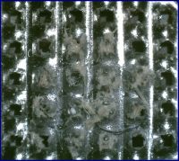
I wonder what these crsytals are. And the white inclusion, third row up from the bottom, third row from the left, that looks to be part of a different crystal system. Could they have formed only once the glass envelope was broken and air was admitted?
And then there's what looks like a piece of wire, partly occulted by the crystals, and which must be some kind of contamination, perhaps at the manufacturing stage. An ultra fine wire it would have to be too.
Funny how I completely missed all this before, but that's what comes from forgetting that it's just as easy to get lost in an infinitely small space as in an infinitely large one.
Proud Mary, Sat Feb 12 2011, 11:50AM
2X2A Crystal formation in getter grill x20

I wonder what these crsytals are. And the white inclusion, third row up from the bottom, third row from the left, that looks to be part of a different crystal system. Could they have formed only once the glass envelope was broken and air was admitted?
And then there's what looks like a piece of wire, partly occulted by the crystals, and which must be some kind of contamination, perhaps at the manufacturing stage. An ultra fine wire it would have to be too.
Funny how I completely missed all this before, but that's what comes from forgetting that it's just as easy to get lost in an infinitely small space as in an infinitely large one.
Re: Vacuum Rectifiers X-rays report
Proud Mary, Sat Feb 12 2011, 10:29PM
2X2A getter grill single crystal bright field technique x200
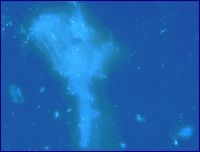
Tentative interpretation: this is a dynamic, evolving system which is still developing.
Krzysztof Penderecki
Proud Mary, Sat Feb 12 2011, 10:29PM
2X2A getter grill single crystal bright field technique x200

Tentative interpretation: this is a dynamic, evolving system which is still developing.
Krzysztof Penderecki

Re: Vacuum Rectifiers X-rays report
Patrick, Sat Feb 12 2011, 10:36PM
Patrick, Sat Feb 12 2011, 10:36PM
Proud Mary wrote ...
2X2A getter grill single crystal bright field technique x200

Tentative interpretation: this is a dynamic, evolving system which is still developing.
Well maybe its absorbing air/water until extinction. Any idea on the identity of the getter and its molar quantity?2X2A getter grill single crystal bright field technique x200

Tentative interpretation: this is a dynamic, evolving system which is still developing.
Re: Vacuum Rectifiers X-rays report
Proud Mary, Sat Feb 12 2011, 11:04PM
Well, it certainly does have a hydrated, water-of-crystallisation look about it, doesn't it?
I'll have to read up about 1940s getter/scavenger practice to guide me in likely directions.
Proud Mary, Sat Feb 12 2011, 11:04PM
Patrick wrote ...
Well maybe its absorbing air/water until extinction. Any idea on the identity of the getter and its molar quantity?
Well maybe its absorbing air/water until extinction. Any idea on the identity of the getter and its molar quantity?
Well, it certainly does have a hydrated, water-of-crystallisation look about it, doesn't it?
I'll have to read up about 1940s getter/scavenger practice to guide me in likely directions.
Re: Vacuum Rectifiers X-rays report
Patrick, Sat Feb 12 2011, 11:17PM
Keep a camera on it and watch it over a few hours, maybe it will grow?
Patrick, Sat Feb 12 2011, 11:17PM
Proud Mary wrote ...
Well, it certainly does have a hydrated, water-of-crystallisation look about it, doesn't it?
It would be a total guess on my part, but it sure strikes me as thin wisps of hydrate crystal type stuff.Well, it certainly does have a hydrated, water-of-crystallisation look about it, doesn't it?
Keep a camera on it and watch it over a few hours, maybe it will grow?
Re: Vacuum Rectifiers X-rays report
Proud Mary, Sat Feb 12 2011, 11:53PM
Lederer, in Contact Potential, Pumps, and Getters RCA, 1940, describes the use of barium-magnesium and barium-aluminium alloy getters, which he says "are brittle at room temperature. It is customary, therefore, to pulverize the alloys and compact the powder into small pellets on a pill press." This description fits the 2X2A case perfectly, as there is a pill shaped pressing on the upper surface of the heat shield above the grill.
As for watching the crystal grow, I have done just that, but not intentionally. I ran a 100 image stack at x1000, which took about ten minutes, but the output image had odd artefacts which you'd only expect to see if the subject had moved during stack compilation. I didn't think that much about it, because it's difficult to avoid vibration altogether at that magnification, making image synthesis problematic for someone with only very basic equipment, and even more basic skills.
Proud Mary, Sat Feb 12 2011, 11:53PM
Patrick wrote ...
Keep a camera on it and watch it over a few hours, maybe it will grow?
Proud Mary wrote ...
Well, it certainly does have a hydrated, water-of-crystallisation look about it, doesn't it?
It would be a total guess on my part, but it sure strikes me as thin wisps of hydrate crystal type stuff.Well, it certainly does have a hydrated, water-of-crystallisation look about it, doesn't it?
Keep a camera on it and watch it over a few hours, maybe it will grow?
Lederer, in Contact Potential, Pumps, and Getters RCA, 1940, describes the use of barium-magnesium and barium-aluminium alloy getters, which he says "are brittle at room temperature. It is customary, therefore, to pulverize the alloys and compact the powder into small pellets on a pill press." This description fits the 2X2A case perfectly, as there is a pill shaped pressing on the upper surface of the heat shield above the grill.
As for watching the crystal grow, I have done just that, but not intentionally. I ran a 100 image stack at x1000, which took about ten minutes, but the output image had odd artefacts which you'd only expect to see if the subject had moved during stack compilation. I didn't think that much about it, because it's difficult to avoid vibration altogether at that magnification, making image synthesis problematic for someone with only very basic equipment, and even more basic skills.
Re: Vacuum Rectifiers X-rays report
Proud Mary, Sun Feb 13 2011, 01:26AM
Aye, Patrick, barium hydroxide octahydrate Ba(OH)2·8H2O is a likely candidate for the crystals - an extremely noxious, toxic substance - though I suppose it could be a complex of barium and magnesium, or barium and aluminium, for all I know. I'm more at home with the preparation of goulash than I am with chemistry!
Proud Mary, Sun Feb 13 2011, 01:26AM
Proud Mary wrote ...
Lederer, in Contact Potential, Pumps, and Getters RCA, 1940, describes the use of barium-magnesium and barium-aluminium alloy getters, which he says "are brittle at room temperature. It is customary, therefore, to pulverize the alloys and compact the powder into small pellets on a pill press." This description fits the 2X2A case perfectly, as there is a pill shaped pressing on the upper surface of the heat shield above the grill.
As for watching the crystal grow, I have done just that, but not intentionally. I ran a 100 image stack at x1000, which took about ten minutes, but the output image had odd artefacts which you'd only expect to see if the subject had moved during stack compilation. I didn't think that much about it, because it's difficult to avoid vibration altogether at that magnification, making image synthesis problematic for someone with only very basic equipment, and even more basic skills.
Patrick wrote ...
Keep a camera on it and watch it over a few hours, maybe it will grow?
Proud Mary wrote ...
Well, it certainly does have a hydrated, water-of-crystallisation look about it, doesn't it?
It would be a total guess on my part, but it sure strikes me as thin wisps of hydrate crystal type stuff.Well, it certainly does have a hydrated, water-of-crystallisation look about it, doesn't it?
Keep a camera on it and watch it over a few hours, maybe it will grow?
Lederer, in Contact Potential, Pumps, and Getters RCA, 1940, describes the use of barium-magnesium and barium-aluminium alloy getters, which he says "are brittle at room temperature. It is customary, therefore, to pulverize the alloys and compact the powder into small pellets on a pill press." This description fits the 2X2A case perfectly, as there is a pill shaped pressing on the upper surface of the heat shield above the grill.
As for watching the crystal grow, I have done just that, but not intentionally. I ran a 100 image stack at x1000, which took about ten minutes, but the output image had odd artefacts which you'd only expect to see if the subject had moved during stack compilation. I didn't think that much about it, because it's difficult to avoid vibration altogether at that magnification, making image synthesis problematic for someone with only very basic equipment, and even more basic skills.
Aye, Patrick, barium hydroxide octahydrate Ba(OH)2·8H2O is a likely candidate for the crystals - an extremely noxious, toxic substance - though I suppose it could be a complex of barium and magnesium, or barium and aluminium, for all I know. I'm more at home with the preparation of goulash than I am with chemistry!
Re: Vacuum Rectifiers X-rays report
plazmatron, Sun Feb 13 2011, 01:28AM
This is a great thread. I have never seen so may x-ray photons emerge from a tube in Field emission mode!
It seems to be surviving long enough for some decent experiments too.
Les
plazmatron, Sun Feb 13 2011, 01:28AM
This is a great thread. I have never seen so may x-ray photons emerge from a tube in Field emission mode!
It seems to be surviving long enough for some decent experiments too.
Les
Re: Vacuum Rectifiers X-rays report
Proud Mary, Sun Feb 13 2011, 01:34AM
You're right, Les, that the abundant emission of these Soviet 2X2As is unusual, and that we should try to explain it. A new destructive test suggests itself: running a 'new old stock' 2X2A in field emission mode for, say, 5 hrs, (or until failure, whichever is sooner) followed by micrographical examination of the valve's internal elements. This should show up as pitting, cracking, fissures, melting, etc where the electrons have been impacting, and so reveal the origin of the X-rays.
I'm working up some dosimetry on 2X2A using the Victoreen Rad-Check Plus, and will have something to show for it in the coming week.
Proud Mary, Sun Feb 13 2011, 01:34AM
plazmatron wrote ...
This is a great thread. I have never seen so may x-ray photons emerge from a tube in Field emission mode!
It seems to be surviving long enough for some decent experiments too.
Les
This is a great thread. I have never seen so may x-ray photons emerge from a tube in Field emission mode!
It seems to be surviving long enough for some decent experiments too.
Les
You're right, Les, that the abundant emission of these Soviet 2X2As is unusual, and that we should try to explain it. A new destructive test suggests itself: running a 'new old stock' 2X2A in field emission mode for, say, 5 hrs, (or until failure, whichever is sooner) followed by micrographical examination of the valve's internal elements. This should show up as pitting, cracking, fissures, melting, etc where the electrons have been impacting, and so reveal the origin of the X-rays.
I'm working up some dosimetry on 2X2A using the Victoreen Rad-Check Plus,
 and will have something to show for it in the coming week.
 Re: Vacuum Rectifiers X-rays report
plazmatron, Sun Feb 13 2011, 07:39PM
Contrary to what you might expect, it doesn't have to be obviously sharp points that are responsible for field emission.
Based on what I have seen here, and my own experiments (building field emission cathodes), it may well be the entire inner surface of the anode bell that is emitting electrons in a very uniform fashion.
As I recall, the last American 2X2 I had, had an obviously pressed thin anode bell, with a turned out edge. The surface was very smooth. However, as is evident is Stellas photomicrographs, the entire surface of the Russian anode bell is very rough, and under magnification somewhat crystalline in appearance. All of those tiny points on the surface of the metal may make ideal field emitters.
Of course, this is just a hypothesis, so I will order a couple off fleabay, remove the anodes, and test them in my vacuum rig.
Les
plazmatron, Sun Feb 13 2011, 07:39PM
Proud Mary wrote ...
You're right, Les, that the abundant emission of these Soviet 2X2As is unusual, and that we should try to explain it. A new destructive test suggests itself: running a 'new old stock' 2X2A in field emission mode for, say, 5 hrs, (or until failure, whichever is sooner) followed by micrographical examination of the valve's internal elements. This should show up as pitting, cracking, fissures, melting, etc where the electrons have been impacting, and so reveal the origin of the X-rays.
You're right, Les, that the abundant emission of these Soviet 2X2As is unusual, and that we should try to explain it. A new destructive test suggests itself: running a 'new old stock' 2X2A in field emission mode for, say, 5 hrs, (or until failure, whichever is sooner) followed by micrographical examination of the valve's internal elements. This should show up as pitting, cracking, fissures, melting, etc where the electrons have been impacting, and so reveal the origin of the X-rays.
Contrary to what you might expect, it doesn't have to be obviously sharp points that are responsible for field emission.
Based on what I have seen here, and my own experiments (building field emission cathodes), it may well be the entire inner surface of the anode bell that is emitting electrons in a very uniform fashion.
As I recall, the last American 2X2 I had, had an obviously pressed thin anode bell, with a turned out edge. The surface was very smooth. However, as is evident is Stellas photomicrographs, the entire surface of the Russian anode bell is very rough, and under magnification somewhat crystalline in appearance. All of those tiny points on the surface of the metal may make ideal field emitters.
Of course, this is just a hypothesis, so I will order a couple off fleabay, remove the anodes, and test them in my vacuum rig.
Les
Re: Vacuum Rectifiers X-rays report
Proud Mary, Sun Feb 13 2011, 09:29PM
Golly, that's very thoughtful of you, Les. Radu will be delighted.
Of course, you're right to suggest that the field emission points need not necessarily be obvious to the naked eye. For the moment, at least, I can't think of any certain means for locating the emission source/s - what I shall call the effective cathode to avoid confusion - but am more confident in finding thermally-induced changes in the micro-topography caused by electron strikes on the effective anode - so long as these aren't so diffuse as to defeat detection with my simple equipment.
If nothing obvious to the microscope appears after a good 'burning in' of the valve - or burning out, as the case may be - then I can etch the surface in the hope of revealing the grain structure and any changes in it, reflection pleochromism under polarised light, and so on. Won't know till we get there.
But it wouldn't be an experiment if we already knew the outcome.
Proud Mary, Sun Feb 13 2011, 09:29PM
plazmatron wrote ...
I will order a couple off fleabay, remove the anodes, and test them in my vacuum rig.
I will order a couple off fleabay, remove the anodes, and test them in my vacuum rig.
Golly, that's very thoughtful of you, Les. Radu will be delighted.

Of course, you're right to suggest that the field emission points need not necessarily be obvious to the naked eye. For the moment, at least, I can't think of any certain means for locating the emission source/s - what I shall call the effective cathode to avoid confusion - but am more confident in finding thermally-induced changes in the micro-topography caused by electron strikes on the effective anode - so long as these aren't so diffuse as to defeat detection with my simple equipment.
If nothing obvious to the microscope appears after a good 'burning in' of the valve - or burning out, as the case may be - then I can etch the surface in the hope of revealing the grain structure and any changes in it, reflection pleochromism under polarised light, and so on. Won't know till we get there.
But it wouldn't be an experiment if we already knew the outcome.

Re: Vacuum Rectifiers X-rays report
plazmatron, Mon Feb 14 2011, 12:08AM
Not at all, I am every bit as curious as everyone else on here. I have just ordered 4 tubes from Lithuania, so they should be here in a week or two.
I will have the opportunity to use whatever anode material I choose. Tungsten will be my first choice, however maybe something with a lower melting point will prove more useful in determining where electron impacts are taking place.
This is a very cool discovery Radhoo!
plazmatron, Mon Feb 14 2011, 12:08AM
Proud Mary wrote ...
Golly, that's very thoughtful of you, Les. Radu will be delighted.
Golly, that's very thoughtful of you, Les. Radu will be delighted.

Not at all, I am every bit as curious as everyone else on here. I have just ordered 4 tubes from Lithuania, so they should be here in a week or two.
Proud Mary wrote ...
Of course, you're right to suggest that the field emission points need not necessarily be obvious to the naked eye. For the moment, at least, I can't think of any certain means for locating the emission source/s - what I shall call the effective cathode to avoid confusion - but am more confident in finding thermally-induced changes in the micro-topography caused by electron strikes on the effective anode - so long as these aren't so diffuse as to defeat detection with my simple equipment.
Of course, you're right to suggest that the field emission points need not necessarily be obvious to the naked eye. For the moment, at least, I can't think of any certain means for locating the emission source/s - what I shall call the effective cathode to avoid confusion - but am more confident in finding thermally-induced changes in the micro-topography caused by electron strikes on the effective anode - so long as these aren't so diffuse as to defeat detection with my simple equipment.
I will have the opportunity to use whatever anode material I choose. Tungsten will be my first choice, however maybe something with a lower melting point will prove more useful in determining where electron impacts are taking place.
This is a very cool discovery Radhoo!

Re: Vacuum Rectifiers X-rays report
radhoo, Mon Feb 14 2011, 10:16AM
Hi Les,
I'd love an uranium anode tube. That would create some very interesting x-rays. Or should I call them Gamma already? Apparently the difference is in the means of producing them, and not the energy.
radhoo, Mon Feb 14 2011, 10:16AM
Hi Les,
plazmatron wrote ...
Not at all, I am every bit as curious as everyone else on here. I have just ordered 4 tubes from Lithuania, so they should be here in a week or two.
If you purchased them from Gintaras (Store KWTubes) it might take a while, I also got my tubes from him, he sells a lot of good stuff, but recently he left for a trip in Cambodia, and no news from him since then. Malaria? hope not.Not at all, I am every bit as curious as everyone else on here. I have just ordered 4 tubes from Lithuania, so they should be here in a week or two.
I'd love an uranium anode tube. That would create some very interesting x-rays. Or should I call them Gamma already? Apparently the difference is in the means of producing them, and not the energy.
Re: Vacuum Rectifiers X-rays report
Proud Mary, Mon Feb 14 2011, 12:51PM
Gintaras is a lover of costly Brompton folding bicycles, and travels round the world to folding bicycle conventions and activities.

Proud Mary, Mon Feb 14 2011, 12:51PM
radhoo wrote ...
If you purchased them from Gintaras (Store KWTubes) it might take a while, I also got my tubes from him, he sells a lot of good stuff, but recently he left for a trip in Cambodia, and no news from him since then. Malaria? hope not.
If you purchased them from Gintaras (Store KWTubes) it might take a while, I also got my tubes from him, he sells a lot of good stuff, but recently he left for a trip in Cambodia, and no news from him since then. Malaria? hope not.
Gintaras is a lover of costly Brompton folding bicycles, and travels round the world to folding bicycle conventions and activities.

Re: Vacuum Rectifiers X-rays report
radhoo, Mon Feb 14 2011, 06:34PM
About Gintaras: Now I understand how does he manage to carry his bike all around the globe. Nice hobby, a bit risky.
I believe I finally have some answers explaining the 2X2 case:
1- I also believe the entire bell surface is an emitter. If this wasn't true, I wouldn't have obtained such an uniform illumination on the fluorescent screen. The emission is stronger at 360degrees around the tube, were the space between the bell and the central filament is shorter, and dims gradually towards the top of the bell. However the illumination remains uniform both on horizontal and vertical plans, as I have shown with all the pictures and measurements above.
2- some information from a Romanian forum, on a thread focused on vacuum tubes: the oxide covering the filament is either barium oxide or strontium oxide. I would assume this is barium, but Proud Mary could help me with a simple chemistry test: put a little piece of the oxide in an colorless flame: barium makes the flame green, while the strontium makes it red.
Barium oxide would be an excellent target for electron bombardment and I believe it can hold more damage than a simple tungsten filament.
3- the metal grill with crystals pictured by Proud Mary under microscope, is used to absorb the remaining gases after the tube has been vacuumed. So the crystals could be the resulting compounds of highly reactive chemicals placed on that plate. I don't think the plate has any influence on the x-ray output.
4- All the above is nothing new for other tubes as well. So what makes the difference?
Take the following picture as a reference:
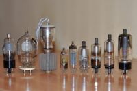
I invite the readers to take a guess on which of the tubes above would make the best X-ray emitter, from left to the right:
2X2 , V1-0.1/30 , VI3-70/30 , DY86, PY88, 3BW2 , 3A3C , 3CZ3 , 6LJ6A
I believe I know the key criteria that causes the abundant emission for the 2X2 (at least as compared to the tubes I currently have). I still need to run some tests to confirm it, so I will get back on this.
radhoo, Mon Feb 14 2011, 06:34PM
About Gintaras: Now I understand how does he manage to carry his bike all around the globe. Nice hobby, a bit risky.
I believe I finally have some answers explaining the 2X2 case:
1- I also believe the entire bell surface is an emitter. If this wasn't true, I wouldn't have obtained such an uniform illumination on the fluorescent screen. The emission is stronger at 360degrees around the tube, were the space between the bell and the central filament is shorter, and dims gradually towards the top of the bell. However the illumination remains uniform both on horizontal and vertical plans, as I have shown with all the pictures and measurements above.
2- some information from a Romanian forum, on a thread focused on vacuum tubes: the oxide covering the filament is either barium oxide or strontium oxide. I would assume this is barium, but Proud Mary could help me with a simple chemistry test: put a little piece of the oxide in an colorless flame: barium makes the flame green, while the strontium makes it red.
Barium oxide would be an excellent target for electron bombardment and I believe it can hold more damage than a simple tungsten filament.
3- the metal grill with crystals pictured by Proud Mary under microscope, is used to absorb the remaining gases after the tube has been vacuumed. So the crystals could be the resulting compounds of highly reactive chemicals placed on that plate. I don't think the plate has any influence on the x-ray output.
4- All the above is nothing new for other tubes as well. So what makes the difference?
Take the following picture as a reference:

I invite the readers to take a guess on which of the tubes above would make the best X-ray emitter, from left to the right:
2X2 , V1-0.1/30 , VI3-70/30 , DY86, PY88, 3BW2 , 3A3C , 3CZ3 , 6LJ6A
I believe I know the key criteria that causes the abundant emission for the 2X2 (at least as compared to the tubes I currently have). I still need to run some tests to confirm it, so I will get back on this.
Re: Vacuum Rectifiers X-rays report
Proud Mary, Mon Feb 14 2011, 07:41PM
One of the Russian kenotrons - 2nd and 3rd from the left, perhaps?
Do keep in mind in your theorising that there a number of distinctly different modes of X-ray production, which for simplicity I'll divide first into 'hard vacuum' and 'soft vacuum' classes.
The high vacuum Coolidge tube with thermionic cathode needs no explanation here, but the earlier unheated Röntgen tubes deserve closer attention:
Introduction to Gas Discharge Tubes and Cold Cathode X-ray Tubes
Oak Ridge University Associates
Regulating Gas Pressure
For proper operation, the gas pressure inside the tube needed to be on the order of 0.2 to 0.5 mm Hg. A tube with higher pressures was too "soft" while a tube with a lower pressure had too "hard" a vacuum. Initially, outgassing from some of the tubes metal components (especially the aluminum) would soften the tube, but over time it was common for the gas pressure to decrease as the residual gas in the tube was adsorbed on the tube’s walls and other components. This hardening of the tube reduced the intensity of the x-rays. At the same time, the x-rays became more penetrating (higher energy).
While the long term trend was towards a hardening of the tube, the pressure in the tubes could vary in an unpredictable fashion over the short term. For example, during use the gas pressure could increase temporarily as the glass wall of the tube heated up and released some of the adsorbed gas.
In general, two methods were employed to correct for the hardening of the tube:
1. The most common method was to add a regulator (side arm) to the tube which contained a material that released a gas when heated, e.g., asbestos impregnated with some chemical such as sodium hydrate or potassium hydrate. Potash and charcoal were also used.
In the simplest designs, the regulator had to be heated directly in a flame. However, the more common self-regulating systems didn't require the operator to do anything. These self-regulating tubes employed a lever (usually a wire) attached at one end to the regulator. The free end was positioned at a specific distance from the connection for the cathode. As the tube hardened, the flow of current from the cathode to the anode decreased. Eventually, the current would jump the spark gap between the cathode connection and the tip of the lever. This caused the material in the regulator to heat up and increase the pressure in the x-ray tube. The sparking ceased when the pressure in the tube was reduced to an acceptable level. If a harder tube (more penetrating x-rays) tube was desired, a large gap was used. For a softer tube (more contrast), a small gap was employed.
2. Another approach, developed by Villard, employed the principle of osmosis. The glass wall was penetrated by a very fine capillary of platinum or palladium. Upon heating the latter to a red glow, hydrogen diffused through the platinum/palladium into the tube and increased the gas pressure.
Now perhaps you will understand my interest in the getter material, and the possible effects it might have on the gas pressure inside the tube. Of course, it may have nothing to do with the 2X2A X-ray production at all - but we should not exclude it as a possible factor without good evidence.
Proud Mary, Mon Feb 14 2011, 07:41PM
radhoo wrote ...
About Gintaras: Now I understand how does he manage to carry his bike all around the globe. Nice hobby, a bit risky.
I believe I finally have some answers explaining the 2X2 case:
1- I also believe the entire bell surface is an emitter. If this wasn't true, I wouldn't have obtained such an uniform illumination on the fluorescent screen. The emission is stronger at 360degrees around the tube, were the space between the bell and the central filament is shorter, and dims gradually towards the top of the bell. However the illumination remains uniform both on horizontal and vertical plans, as I have shown with all the pictures and measurements above.
2- some information from a Romanian forum, on a thread focused on vacuum tubes: the oxide covering the filament is either barium oxide or strontium oxide. I would assume this is barium, but Proud Mary could help me with a simple chemistry test: put a little piece of the oxide in an colorless flame: barium makes the flame green, while the strontium makes it red.
Barium oxide would be an excellent target for electron bombardment and I believe it can hold more damage than a simple tungsten filament.
3- the metal grill with crystals pictured by Proud Mary under microscope, is used to absorb the remaining gases after the tube has been vacuumed. So the crystals could be the resulting compounds of highly reactive chemicals placed on that plate. I don't think the plate has any influence on the x-ray output.
4- All the above is nothing new for other tubes as well. So what makes the difference?
Take the following picture as a reference:

I invite the readers to take a guess on which of the tubes above would make the best X-ray emitter, from left to the right:
2X2 , V1-0.1/30 , VI3-70/30 , DY86, PY88, 3BW2 , 3A3C , 3CZ3 , 6LJ6A
I believe I know the key criteria that causes the abundant emission for the 2X2 (at least as compared to the tubes I currently have). I still need to run some tests to confirm it, so I will get back on this.
About Gintaras: Now I understand how does he manage to carry his bike all around the globe. Nice hobby, a bit risky.
I believe I finally have some answers explaining the 2X2 case:
1- I also believe the entire bell surface is an emitter. If this wasn't true, I wouldn't have obtained such an uniform illumination on the fluorescent screen. The emission is stronger at 360degrees around the tube, were the space between the bell and the central filament is shorter, and dims gradually towards the top of the bell. However the illumination remains uniform both on horizontal and vertical plans, as I have shown with all the pictures and measurements above.
2- some information from a Romanian forum, on a thread focused on vacuum tubes: the oxide covering the filament is either barium oxide or strontium oxide. I would assume this is barium, but Proud Mary could help me with a simple chemistry test: put a little piece of the oxide in an colorless flame: barium makes the flame green, while the strontium makes it red.
Barium oxide would be an excellent target for electron bombardment and I believe it can hold more damage than a simple tungsten filament.
3- the metal grill with crystals pictured by Proud Mary under microscope, is used to absorb the remaining gases after the tube has been vacuumed. So the crystals could be the resulting compounds of highly reactive chemicals placed on that plate. I don't think the plate has any influence on the x-ray output.
4- All the above is nothing new for other tubes as well. So what makes the difference?
Take the following picture as a reference:

I invite the readers to take a guess on which of the tubes above would make the best X-ray emitter, from left to the right:
2X2 , V1-0.1/30 , VI3-70/30 , DY86, PY88, 3BW2 , 3A3C , 3CZ3 , 6LJ6A
I believe I know the key criteria that causes the abundant emission for the 2X2 (at least as compared to the tubes I currently have). I still need to run some tests to confirm it, so I will get back on this.
One of the Russian kenotrons - 2nd and 3rd from the left, perhaps?
Do keep in mind in your theorising that there a number of distinctly different modes of X-ray production, which for simplicity I'll divide first into 'hard vacuum' and 'soft vacuum' classes.
The high vacuum Coolidge tube with thermionic cathode needs no explanation here, but the earlier unheated Röntgen tubes deserve closer attention:
Introduction to Gas Discharge Tubes and Cold Cathode X-ray Tubes
Oak Ridge University Associates
Regulating Gas Pressure
For proper operation, the gas pressure inside the tube needed to be on the order of 0.2 to 0.5 mm Hg. A tube with higher pressures was too "soft" while a tube with a lower pressure had too "hard" a vacuum. Initially, outgassing from some of the tubes metal components (especially the aluminum) would soften the tube, but over time it was common for the gas pressure to decrease as the residual gas in the tube was adsorbed on the tube’s walls and other components. This hardening of the tube reduced the intensity of the x-rays. At the same time, the x-rays became more penetrating (higher energy).
While the long term trend was towards a hardening of the tube, the pressure in the tubes could vary in an unpredictable fashion over the short term. For example, during use the gas pressure could increase temporarily as the glass wall of the tube heated up and released some of the adsorbed gas.
In general, two methods were employed to correct for the hardening of the tube:
1. The most common method was to add a regulator (side arm) to the tube which contained a material that released a gas when heated, e.g., asbestos impregnated with some chemical such as sodium hydrate or potassium hydrate. Potash and charcoal were also used.
In the simplest designs, the regulator had to be heated directly in a flame. However, the more common self-regulating systems didn't require the operator to do anything. These self-regulating tubes employed a lever (usually a wire) attached at one end to the regulator. The free end was positioned at a specific distance from the connection for the cathode. As the tube hardened, the flow of current from the cathode to the anode decreased. Eventually, the current would jump the spark gap between the cathode connection and the tip of the lever. This caused the material in the regulator to heat up and increase the pressure in the x-ray tube. The sparking ceased when the pressure in the tube was reduced to an acceptable level. If a harder tube (more penetrating x-rays) tube was desired, a large gap was used. For a softer tube (more contrast), a small gap was employed.
2. Another approach, developed by Villard, employed the principle of osmosis. The glass wall was penetrated by a very fine capillary of platinum or palladium. Upon heating the latter to a red glow, hydrogen diffused through the platinum/palladium into the tube and increased the gas pressure.
Now perhaps you will understand my interest in the getter material, and the possible effects it might have on the gas pressure inside the tube. Of course, it may have nothing to do with the 2X2A X-ray production at all - but we should not exclude it as a possible factor without good evidence.
Re: Vacuum Rectifiers X-rays report
plazmatron, Mon Feb 14 2011, 09:02PM
Yes, it is also completely possible that this particular make of 2X2's just so happen to have the correct level of vacuum to function as a good old 1900's cold cathode tube. The internal pressure may well be governed by the getter type, as well as the speed at which residual gas atoms are cleaned up, during use. However the envelope really looks to small to be able to pull off such a balancing act with ease.
All quite intriguing!
Les
plazmatron, Mon Feb 14 2011, 09:02PM
Proud Mary wrote ...
Now perhaps you will understand my interest in the getter material, and the possible effects it might have on the gas pressure inside the tube. Of course, it may have nothing to do with the 2X2A X-ray production at all - but we should not exclude it as a possible factor without good evidence.
Now perhaps you will understand my interest in the getter material, and the possible effects it might have on the gas pressure inside the tube. Of course, it may have nothing to do with the 2X2A X-ray production at all - but we should not exclude it as a possible factor without good evidence.
Yes, it is also completely possible that this particular make of 2X2's just so happen to have the correct level of vacuum to function as a good old 1900's cold cathode tube. The internal pressure may well be governed by the getter type, as well as the speed at which residual gas atoms are cleaned up, during use. However the envelope really looks to small to be able to pull off such a balancing act with ease.
All quite intriguing!
Les
Re: Vacuum Rectifiers X-rays report
radhoo, Mon Feb 14 2011, 09:25PM
I understand your interest in the getter, but the medium inside the tube doesn't change much on the short term. So given a particular tube, it will either emit "plentiful" x-rays, or it will not.
Regarding the choice you made, I have to admit that I was eagerly waiting for my new big Russian tubes to arrive. I got them today, and I didn't have to power them to guess something that after a few simple tests, proved to be true. Funny but I picked the small DY86 as a potential candidate, among the other tubes in the picture above. Why? Here are some facts:
11.Other vacuum tubes
Note: Again, I will be using several vacuum rectifier tubes or shunts, in inverse polarization at 50KV.
1) The Russian V1 0.1/30 . I have 4 of these. Here are some results:
TEST A: Tube in vertical position, fluorescent screen in close proximity (2-3cm):
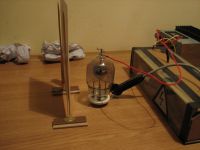
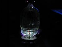

The first pictures shows the setup,
The second and forth pictures show the fluorescent screen while the tube is applied 50KV in inverse polarization (no fluorescence),
The third picture shows a closeup on the tube, while running.
Notice the glass blue fluorescence, seen on other X-ray tubes, is missing! ; instead the bottom of the tube is strongly illuminated. One of my 4 tubes, has a small metal blocker right under the anode bell . Not this one. Wondering why, I turned the tube in horizontal position:
TEST B: Tube in horizontal position, bottom oriented towards fluorescent screen:
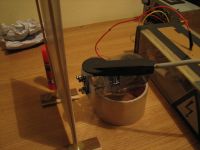

Results? Nothing on the fluorescent screen, after 15seconds of exposure (the same parameters as for the 2X2).
The Radex 1706 was picking up small amounts of radiation. Placed at 3 meters : 0.42uSv/h
2. To make sure that my setup is functioning correctly, I replaced the v1-0.1/30 for the 2X2:
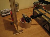
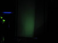
Much better! The Radex 1706 was now indicating 54uSv/h placed in the same place at 3meters . Not reliable but a lot different (good text for a quote :) ).
3. So far so good. I had to try the PY88 . For reasons not related to X-rays, vacuum or tube size, this was unsuitable to test my idea. So going for the next test:
4. The DY86 . I did some tests with this kind of tube some time ago. But now I have another one that seems different. Applying 50KV created a lot of flashovers, a nice show of sparks, putting the tube in real danger. Some tape fixed the problem. Here are some pictures:
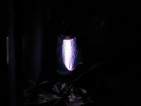
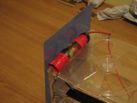
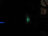
First picture: The tube connected to the supply is covered in sparks
Second picture: Using some tape to better insulate the tube's terminals
Third picture: Some nice fluorescence on the screen, comparable in intensity (energy level) with that produced by the 2X2. Of course, the field is distributed in a narrower shape (among other disadvantages like small tube size: thermal and insulation problems, small vacuum volume inside possible cause for parameters changes in time, etc).
My conclusion
Lately I got used to check the medium inside a sealed tube, for photoelectric effect, using a 405nm laser 5mW laser pointer.
By doing so I quickly was able to distinguish between vacuum tubes and inert gas tubes (like spark gaps or light bulbs).
Not only that, but using a multimeter I had the chance to notice some minimum and maximum values on the voltage outputted by a tube, while illuminated with the UV laser.
This was the first test I did today, to make sure the vacuum inside the new tubes is well preserved.
Here are some maximum voltage values, obtained by continuously changing the laser target (I was usually aiming either the anode or the cathode). No matter what I did, I couldn't get more voltage out of a given tube, using the laser pointer:
2X2 --> 200mV
6LJ6A --> 0.1mV
First V1-0.1/30 --> 0.1mV
Second V1-0.1/30 --> 0.5mV
Third V1-0.1/30 --> 0.1mV
Fourth V1-0.1/30 --> 1mV
PY88 --> 50mV
DY86 --> 300mV!!!
The previously used DY86 --> 0.3mV
Another DY86 with the seal cracked and the metallic surface inside turned white: 0V
So the last property that I believe makes the 2X2 so good at emitting X-Rays, besides the first I discussed in the previous post, is the hard vacuum inside, a feature highlighted by the photoelectric experiment described above.
As can be seen, the big Russian tubes only have a so-called "soft" vacuum inside.
Proud Mary I believe you brought the discussion to the right place, with the article you've quoted.
As for the 2X2, it is presented as a "High-vacuum Rectifier ", a feature that I believe it is responsible for the nice X-ray emission:

I will try to bring more evidence that a simple laser pointer test can indicate whether a vacuum rectifier tube is suitable for X-ray emission, given some preliminary requirements are met like: high-Z target, electrode geometry, etc . For the time I had for this evening's test, this is all I could come with.
radhoo, Mon Feb 14 2011, 09:25PM
I understand your interest in the getter, but the medium inside the tube doesn't change much on the short term. So given a particular tube, it will either emit "plentiful" x-rays, or it will not.
Regarding the choice you made, I have to admit that I was eagerly waiting for my new big Russian tubes to arrive. I got them today, and I didn't have to power them to guess something that after a few simple tests, proved to be true. Funny but I picked the small DY86 as a potential candidate, among the other tubes in the picture above. Why? Here are some facts:
11.Other vacuum tubes
Note: Again, I will be using several vacuum rectifier tubes or shunts, in inverse polarization at 50KV.
1) The Russian V1 0.1/30 . I have 4 of these. Here are some results:
TEST A: Tube in vertical position, fluorescent screen in close proximity (2-3cm):


The first pictures shows the setup,
The second and forth pictures show the fluorescent screen while the tube is applied 50KV in inverse polarization (no fluorescence),
The third picture shows a closeup on the tube, while running.
Notice the glass blue fluorescence, seen on other X-ray tubes, is missing! ; instead the bottom of the tube is strongly illuminated. One of my 4 tubes, has a small metal blocker right under the anode bell . Not this one. Wondering why, I turned the tube in horizontal position:
TEST B: Tube in horizontal position, bottom oriented towards fluorescent screen:


Results? Nothing on the fluorescent screen, after 15seconds of exposure (the same parameters as for the 2X2).
The Radex 1706 was picking up small amounts of radiation. Placed at 3 meters : 0.42uSv/h
2. To make sure that my setup is functioning correctly, I replaced the v1-0.1/30 for the 2X2:


Much better! The Radex 1706 was now indicating 54uSv/h placed in the same place at 3meters . Not reliable but a lot different (good text for a quote :) ).
3. So far so good. I had to try the PY88 . For reasons not related to X-rays, vacuum or tube size, this was unsuitable to test my idea. So going for the next test:
4. The DY86 . I did some tests with this kind of tube some time ago. But now I have another one that seems different. Applying 50KV created a lot of flashovers, a nice show of sparks, putting the tube in real danger. Some tape fixed the problem. Here are some pictures:


First picture: The tube connected to the supply is covered in sparks
Second picture: Using some tape to better insulate the tube's terminals
Third picture: Some nice fluorescence on the screen, comparable in intensity (energy level) with that produced by the 2X2. Of course, the field is distributed in a narrower shape (among other disadvantages like small tube size: thermal and insulation problems, small vacuum volume inside possible cause for parameters changes in time, etc).
My conclusion
Lately I got used to check the medium inside a sealed tube, for photoelectric effect, using a 405nm laser 5mW laser pointer.
By doing so I quickly was able to distinguish between vacuum tubes and inert gas tubes (like spark gaps or light bulbs).
Not only that, but using a multimeter I had the chance to notice some minimum and maximum values on the voltage outputted by a tube, while illuminated with the UV laser.
This was the first test I did today, to make sure the vacuum inside the new tubes is well preserved.
Here are some maximum voltage values, obtained by continuously changing the laser target (I was usually aiming either the anode or the cathode). No matter what I did, I couldn't get more voltage out of a given tube, using the laser pointer:
2X2 --> 200mV
6LJ6A --> 0.1mV
First V1-0.1/30 --> 0.1mV
Second V1-0.1/30 --> 0.5mV
Third V1-0.1/30 --> 0.1mV
Fourth V1-0.1/30 --> 1mV
PY88 --> 50mV
DY86 --> 300mV!!!
The previously used DY86 --> 0.3mV
Another DY86 with the seal cracked and the metallic surface inside turned white: 0V
So the last property that I believe makes the 2X2 so good at emitting X-Rays, besides the first I discussed in the previous post, is the hard vacuum inside, a feature highlighted by the photoelectric experiment described above.
As can be seen, the big Russian tubes only have a so-called "soft" vacuum inside.
Proud Mary I believe you brought the discussion to the right place, with the article you've quoted.
As for the 2X2, it is presented as a "High-vacuum Rectifier ", a feature that I believe it is responsible for the nice X-ray emission:

I will try to bring more evidence that a simple laser pointer test can indicate whether a vacuum rectifier tube is suitable for X-ray emission, given some preliminary requirements are met like: high-Z target, electrode geometry, etc . For the time I had for this evening's test, this is all I could come with.
Re: Vacuum Rectifiers X-rays report
Proud Mary, Mon Feb 14 2011, 10:32PM
Just a short reaction for now, as I am busy:
The appeal of small EHT rectifiers like DY86, and even smaller types like EY51 is that you get a correspondingly smaller anode spot than with, for example, the large EHT shunt stabiliser triodes. I found DY86 to emit X-rays when excited with 40kV, but didn't explore it further because of the flashover problems you've described, and having far better sources to hand.
Your photoelectric experiments are interesting. How much of your measured potential difference could be due to the Seebeck effect? Did you take into account the likely Galvani potential, or 'contact potential' values - the flow of electrons from a low work function metal to a high work function metal - which can be as much as one or two volts in some cases, and is always a factor in thermionic valve design. (You only need think of a permanent bias of 2V on the grid of an audio triode, for example, to see why, but in thermionic diode power rectifiers, compensating for Galvani potential will not have been a design consideration, as it is with multigrid valves) Even the smallest contamination of a metal surface can change its work function by a great amount. As you will know, work function directly affects field emission and so the production of X-rays in our experiment.
Moreover, according to Lederer, (1940 ibid) barium metal evaporates from barium oxide cathodes, and condenses on cooler electrodes in the valve envelope, so wherever electrons are impacting they are probably impacting on a barium nanolayer. I will try to show that this is so with a Gy:kV graph of 2X2A from 15kV - 40kV which will be ready at the weekend.
Re: Vacuum Rectifiers X-rays report
radhoo, Tue Feb 15 2011, 01:23AM
Perhaps I omitted some of the steps of my simple experiment: the bottom pins of the vacuum tube to be tested are connected together, and then to one of the two multimeter probes. The top anode connector goes to the second multimeter probe.
Given an approximately constant room normal temperature no Peltier effect has been observed based on the multimeter readings.
I am not sure about a possible Galvani potential, but in case it exists, it is not to a significant degree: When the multimeter is connected, small charges of 0.1mV can be recorded, but the experiment was not performed in the absence of light so the cause of these small readings is debatable.
Once the multimeter connected, we can ignore the negligible small values as the potential difference is close to 0.
When applying the UV Laser light, a relatively strong electrical field is detected instantaneously. The current persists as long as the target is illuminated and disappears as the laser light is turned off or moved from the conveniently selected target inside the tube.
Using a light source with a bigger wavelength results in smaller voltages . Eg. a green laser (~500nm) will only produce a charge of aprox. 30mV in a 2X2 as compared to the 405nm laser that goes up to 200mV.
In my opinion, these indications go in close correlation with the photoelectric effect, and we do not need to search for other, more complicated approaches to explain the voltage detected.
It also appears that this property is related to the vacuum inside: probably the photons from my laser, with only a few eV energy, are causing the target to emit electrons, that cannot form a current between the two electrodes supervised by the multimeter, unless there is no barrier in the medium inside the tube (gases).
Comparing various tubes with extremely convenient electrode shapes, there seems to be a relation between their "x-ray emitting performance" and the photoelectric effect observed. More tests are needed to support this empirically.
Regarding the barium nano layer, it is very likely to form in these conditions, still there is a problem considering this layer as a source of emission: this layer can't possibly be deposited perfectly uniform, while my previous tests showed the x-rays are emitted uniformly all around the tube. This is why I believe the main source of emission is in the center of the 2X2 tube - more precisely I believe it is the oxide deposited on the central filament

Re: Vacuum Rectifiers X-rays report
Linas, Tue Feb 15 2011, 07:58AM
try to get GP-5 tube

Linas, Tue Feb 15 2011, 07:58AM
try to get GP-5 tube

Re: Vacuum Rectifiers X-rays report
Proud Mary, Tue Feb 15 2011, 09:23AM
Radu, the frequency of the incident light being the same in all cases, are you saying that the magnitude of your photoelectric voltage is related to the work function of the metal surfaces - as in Einstein's photoelectric equations - and that this property can predict the X-ray performance of the tube?
Re: Vacuum Rectifiers X-rays report
Steve Conner, Tue Feb 15 2011, 09:33AM
Well, the only problem I see is that the photoelectric effect is a kind of electron emission. It tests how well the material works as a photocathode.
I don't see any necessary connection between that, and its performance as an anode for X-ray generation, where it's not emitting electrons, but being bombarded by them.
Except in so far as atoms of heavy metals (barium) have characteristic rays of higher energy, so when bombarded with electrons of high enough voltage, they can make lots of hard X-rays that will penetrate the tube glass efficiently. And don't heavy atoms also have a lower work function, because the outer electrons are further from the nucleus and easier to knock off? The old "electric eye" tubes had photocathodes coated in cesium for that reason.
So maybe Radu's method just detects whether there is any barium in the cathode/anode.
Re: Vacuum Rectifiers X-rays report
Proud Mary, Tue Feb 15 2011, 09:59AM
This was my conjecture in my post above (Wed Jan 26 2011, 05:07PM) where I compared and contrasted the characteristic X-ray spectrum of barium, with the spectra of other common cathode coatings, (i.e. of our effective anode) and concluded that - setting aside the continuous radiation - only the strong barium peaks above 30keV could expect to exit the glass envelope in any quantity.
Proud Mary, Tue Feb 15 2011, 09:59AM
Steve McConner wrote ...
Except in so far as atoms of heavy metals (barium) have characteristic rays of higher energy, so when bombarded with electrons of high enough voltage, they can make lots of hard X-rays that will penetrate the tube glass efficiently.
Except in so far as atoms of heavy metals (barium) have characteristic rays of higher energy, so when bombarded with electrons of high enough voltage, they can make lots of hard X-rays that will penetrate the tube glass efficiently.
This was my conjecture in my post above (Wed Jan 26 2011, 05:07PM) where I compared and contrasted the characteristic X-ray spectrum of barium, with the spectra of other common cathode coatings, (i.e. of our effective anode) and concluded that - setting aside the continuous radiation - only the strong barium peaks above 30keV could expect to exit the glass envelope in any quantity.
Re: Vacuum Rectifiers X-rays report
radhoo, Tue Feb 15 2011, 10:25AM
I need to highlight the preliminary requirements mentioned above. I'm not saying that if a vacuum tube provides high voltages when illuminated it will also emit abundant x-rays. Instead I'm saying that high vacuum is what makes the 2X2 so special and that using the photoelectric effect we have a basic test of getting an idea of the gas pressure inside. This test should stand when comparing various rectifier tubes, that have similar metals in their internal electrodes, similar anode/cathode geometry / similar internal pressure and so on. I don't expect my Cesium-photosensitive tube to be a X-ray emitter, even if illuminated by UV produces close to 800mV!.
Actually I didn't give this much importance, until I got the Russian V1-0.1/30 . First I was delighted to see the simple internals, the large anode bell and nice spacing between the components. It also has one very sharp electrode, not connected to anything, except the bottom pin - a lot of potential for particle experiments.
Then putting some light on the anode / cathode inside the bell enclosure, showed very poor photoelectric results. I had a guess this will not work well for x-rays. To support this idea I then took other tubes for a test, and DY86 was an interesting surprise.
radhoo, Tue Feb 15 2011, 10:25AM
Proud Mary wrote ...
Radu, the frequency of the incident light being the same in all cases, are you saying that the magnitude of your photoelectric voltage is related to the work function of the metal surfaces - as in Einstein's photoelectric equations - and that this property can predict the X-ray performance of the tube?
Radu, the frequency of the incident light being the same in all cases, are you saying that the magnitude of your photoelectric voltage is related to the work function of the metal surfaces - as in Einstein's photoelectric equations - and that this property can predict the X-ray performance of the tube?
Steve McConner wrote ...
So maybe Radu's method just detects whether there is any barium in the cathode/anode.
So maybe Radu's method just detects whether there is any barium in the cathode/anode.
radhoo wrote ...
I will try to bring more evidence that a simple laser pointer test can indicate whether a vacuum rectifier tube is suitable for X-ray emission, given some preliminary requirements are met like: high-Z target, electrode geometry, etc . For the time I had for this evening's test, this is all I could come with.
Steve, Proud Mary, I'm not trying to guess the anode metal characteristics using light. More details follow:I will try to bring more evidence that a simple laser pointer test can indicate whether a vacuum rectifier tube is suitable for X-ray emission, given some preliminary requirements are met like: high-Z target, electrode geometry, etc . For the time I had for this evening's test, this is all I could come with.
I need to highlight the preliminary requirements mentioned above. I'm not saying that if a vacuum tube provides high voltages when illuminated it will also emit abundant x-rays. Instead I'm saying that high vacuum is what makes the 2X2 so special and that using the photoelectric effect we have a basic test of getting an idea of the gas pressure inside. This test should stand when comparing various rectifier tubes, that have similar metals in their internal electrodes, similar anode/cathode geometry / similar internal pressure and so on. I don't expect my Cesium-photosensitive tube to be a X-ray emitter, even if illuminated by UV produces close to 800mV!.
Actually I didn't give this much importance, until I got the Russian V1-0.1/30 . First I was delighted to see the simple internals, the large anode bell and nice spacing between the components. It also has one very sharp electrode, not connected to anything, except the bottom pin - a lot of potential for particle experiments.
Then putting some light on the anode / cathode inside the bell enclosure, showed very poor photoelectric results. I had a guess this will not work well for x-rays. To support this idea I then took other tubes for a test, and DY86 was an interesting surprise.
Re: Vacuum Rectifiers X-rays report
Proud Mary, Tue Feb 15 2011, 10:39AM
Radu, Plazmatron may be able to test your vacuum conjecture.
But one thing is certain: the X-ray spectrum of the 2X2A emission will reveal the identity of the elements making up the effective anode.
Proud Mary, Tue Feb 15 2011, 10:39AM
Radu, Plazmatron may be able to test your vacuum conjecture.
But one thing is certain: the X-ray spectrum of the 2X2A emission will reveal the identity of the elements making up the effective anode.
Re: Vacuum Rectifiers X-rays report
radhoo, Tue Feb 15 2011, 11:14AM
That would be great if he could do it. He mentioned a vacuum rig somewhere. Les, can you go as low as 0.2mm Hg as per the article quoted by Proud Mary, describing the Hard vacuum? Do you have uranium, or at least some ore?
Barium produces a green-yellowish color, but still a green, I have some chloride somewhere, I'll see if I can take a photo for comparison.
radhoo, Tue Feb 15 2011, 11:14AM
That would be great if he could do it. He mentioned a vacuum rig somewhere. Les, can you go as low as 0.2mm Hg as per the article quoted by Proud Mary, describing the Hard vacuum? Do you have uranium, or at least some ore?

radhoo wrote ...
...the oxide covering the filament is either barium oxide or strontium oxide. I would assume this is barium, but Proud Mary could help me with a simple chemistry test: put a little piece of the oxide in an colorless flame: barium makes the flame green, while the strontium makes it red.
Proud Mary, could you test this for me using the broken tube's filament? An ordinary butane flame would do. Both barium and strontium are strong flame "pigments" , they have been used in fireworks, so the color should be easily visible....the oxide covering the filament is either barium oxide or strontium oxide. I would assume this is barium, but Proud Mary could help me with a simple chemistry test: put a little piece of the oxide in an colorless flame: barium makes the flame green, while the strontium makes it red.
Barium produces a green-yellowish color, but still a green, I have some chloride somewhere, I'll see if I can take a photo for comparison.
Re: Vacuum Rectifiers X-rays report
Proud Mary, Tue Feb 15 2011, 11:54AM
I'm sure Les can pump down to a much lower gas pressure than that, if neccessary, but how low he'll have to tell you himself.
As for the colourimetric tests, Radu, do you want me to test the coated cathode cylinder, or the insulated filament inside it, as per my photomicrographs above? I will have to wait until night, to be sure of enough darkness to get a good image.
Proud Mary, Tue Feb 15 2011, 11:54AM
radhoo wrote ...
That would be great if he could do it. He mentioned a vacuum rig somewhere. Les, can you go as low as 0.2mm Hg as per the article quoted by Proud Mary, describing the Hard vacuum? Do you have uranium, or at least some ore?
Barium produces a green-yellowish color, but still a green, I have some chloride somewhere, I'll see if I can take a photo for comparison.
That would be great if he could do it. He mentioned a vacuum rig somewhere. Les, can you go as low as 0.2mm Hg as per the article quoted by Proud Mary, describing the Hard vacuum? Do you have uranium, or at least some ore?

radhoo wrote ...
...the oxide covering the filament is either barium oxide or strontium oxide. I would assume this is barium, but Proud Mary could help me with a simple chemistry test: put a little piece of the oxide in an colorless flame: barium makes the flame green, while the strontium makes it red.
Proud Mary, could you test this for me using the broken tube's filament? An ordinary butane flame would do. Both barium and strontium are strong flame "pigments" , they have been used in fireworks, so the color should be easily visible....the oxide covering the filament is either barium oxide or strontium oxide. I would assume this is barium, but Proud Mary could help me with a simple chemistry test: put a little piece of the oxide in an colorless flame: barium makes the flame green, while the strontium makes it red.
Barium produces a green-yellowish color, but still a green, I have some chloride somewhere, I'll see if I can take a photo for comparison.
I'm sure Les can pump down to a much lower gas pressure than that, if neccessary, but how low he'll have to tell you himself.
As for the colourimetric tests, Radu, do you want me to test the coated cathode cylinder, or the insulated filament inside it, as per my photomicrographs above? I will have to wait until night, to be sure of enough darkness to get a good image.
Re: Vacuum Rectifiers X-rays report
radhoo, Tue Feb 15 2011, 12:13PM
Thank you for this test,
Here is one of your quality photos as a reference:

I am interested both in the cathode cylinder, and the insulated filament.
Looking forward to your results, I am really curious what color you will get. I'd put my bet on barium.


radhoo, Tue Feb 15 2011, 12:13PM
Thank you for this test,
Here is one of your quality photos as a reference:

I am interested both in the cathode cylinder, and the insulated filament.
Looking forward to your results, I am really curious what color you will get. I'd put my bet on barium.


Re: Vacuum Rectifiers X-rays report
Proud Mary, Tue Feb 15 2011, 12:38PM
I'll do the flame test tonight after dinner, Radu. If the cathode coating contains strontium as well as barium, I'm not sure what colour we should expect to see with no spectroscope to separate the red from the green. But we'll find out later...
Proud Mary, Tue Feb 15 2011, 12:38PM
I'll do the flame test tonight after dinner, Radu. If the cathode coating contains strontium as well as barium, I'm not sure what colour we should expect to see with no spectroscope to separate the red from the green. But we'll find out later...

Re: Vacuum Rectifiers X-rays report
hboy007, Tue Feb 15 2011, 04:26PM
Sorry for interrupting with a little question:
I just bought a few DY86s for the fun of it. Has anyone tried external electrodes to affect the field inside the tube? Maybe the flashover problems can be alleviated by adding field shaping electrodes.
hboy007, Tue Feb 15 2011, 04:26PM
Sorry for interrupting with a little question:
I just bought a few DY86s for the fun of it. Has anyone tried external electrodes to affect the field inside the tube? Maybe the flashover problems can be alleviated by adding field shaping electrodes.
Re: Vacuum Rectifiers X-rays report
Proud Mary, Tue Feb 15 2011, 05:26PM
Radu I've just spent an hour looking for my other 2X2As and can't find them anywhere, though I know I have at least five, and perhaps more. I'll look for them again later, in some different crates and boxes, but if I have put them away in the wrong place, this may take some time.
Update: I have found one of them in the bottom of a box of photomultipliers, but will save it for my dosimetry experiment at the weekend. I shan't mind butchering it after that, to test the cathode coating, as I have no real use for them.
I am sorry for any disappointment my forgetfulness may have caused.
Re: Vacuum Rectifiers X-rays report
plazmatron, Tue Feb 15 2011, 06:16PM
1x10e-6 torr on a good day. Way harder than the old gas discharge x-ray tubes of antiquity, and plenty hard enough to quantify any field emission characteristics.
That sounds like an excellent idea. I used a pinhole camera to image to focal spot of a diffraction tube, to determine the line focus windows from the spot focus windows.
I think this tube may require an image intensified setup rather than raw film to image the "anode"........runs off to shed....
plazmatron, Tue Feb 15 2011, 06:16PM
Proud Mary wrote ...
I'm sure Les can pump down to a much lower gas pressure than that, if necessary, but how low he'll have to tell you himself.
I'm sure Les can pump down to a much lower gas pressure than that, if necessary, but how low he'll have to tell you himself.
1x10e-6 torr on a good day. Way harder than the old gas discharge x-ray tubes of antiquity, and plenty hard enough to quantify any field emission characteristics.
Steve McConner wrote ...
The pinhole camera might be worth a try. The "camera" of course is simply a lead sheet with a small hole poked in it. The instructions I saw for making it were to bash an indent in the sheet with a hammer and punch, then cut/file off the little bump that appears on the other side.
The pinhole camera might be worth a try. The "camera" of course is simply a lead sheet with a small hole poked in it. The instructions I saw for making it were to bash an indent in the sheet with a hammer and punch, then cut/file off the little bump that appears on the other side.
That sounds like an excellent idea. I used a pinhole camera to image to focal spot of a diffraction tube, to determine the line focus windows from the spot focus windows.
I think this tube may require an image intensified setup rather than raw film to image the "anode"........runs off to shed....
Re: Vacuum Rectifiers X-rays report
Proud Mary, Tue Feb 15 2011, 06:26PM
A splendid idea. Wish I'd thought of it!
Proud Mary, Tue Feb 15 2011, 06:26PM
plazmatron wrote ...
I think this tube may require an image intensified setup rather than raw film to image the "anode"........runs off to shed....
I think this tube may require an image intensified setup rather than raw film to image the "anode"........runs off to shed....
A splendid idea. Wish I'd thought of it!

Re: Vacuum Rectifiers X-rays report
plazmatron, Tue Feb 15 2011, 10:29PM
OK the intensified pinhole camera works fine.
First off we have an image of the focal spot of a small dental x-ray tube (below).
Note, the resolution is good enough that is is obvious the spot is rectangular, corresponding to the spot etched to the anode face
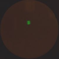
So since I am waiting for KWTubes to send me the 2X2's I thought I would abuse a PD500. It is a poor x-ray emitter, and when driven in field emission mode, emits most of its radiation from near the base of the tube.
Due to the low flux this required a 15 sec exposure of the image intensifier screen.
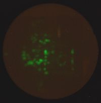
Note the circular structure with two lines either side. This is the end of the heater coil, with metal grid supports either side (hidden visually behind mica end plates!). There are many other emission points from various metal parts near the base of the tube.
For future photos, I will take an AVI and stack the frames, and see if a longer integration period will yield a clearer image.
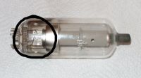
Above is the PD500 with the imaged area circled.
Les
plazmatron, Tue Feb 15 2011, 10:29PM
OK the intensified pinhole camera works fine.
First off we have an image of the focal spot of a small dental x-ray tube (below).
Note, the resolution is good enough that is is obvious the spot is rectangular, corresponding to the spot etched to the anode face

So since I am waiting for KWTubes to send me the 2X2's I thought I would abuse a PD500. It is a poor x-ray emitter, and when driven in field emission mode, emits most of its radiation from near the base of the tube.
Due to the low flux this required a 15 sec exposure of the image intensifier screen.

Note the circular structure with two lines either side. This is the end of the heater coil, with metal grid supports either side (hidden visually behind mica end plates!). There are many other emission points from various metal parts near the base of the tube.
For future photos, I will take an AVI and stack the frames, and see if a longer integration period will yield a clearer image.

Above is the PD500 with the imaged area circled.
Les
Re: Vacuum Rectifiers X-rays report
Proud Mary, Tue Feb 15 2011, 10:34PM
What pd did you put across the PD500, Les?
The imaging of the element supports and leads were my expectation of 2X2As performance, before I saw Radu's results.
Proud Mary, Tue Feb 15 2011, 10:34PM
What pd did you put across the PD500, Les?
The imaging of the element supports and leads were my expectation of 2X2As performance, before I saw Radu's results.
Re: Vacuum Rectifiers X-rays report
plazmatron, Tue Feb 15 2011, 10:40PM
Approx 45kV. (no current measurement I'm afraid, but most assuredly very feeble). It is a really unstable tube driven like this, with occasional x-ray flashes as vacuum breaks down. It was really quite interesting to watch through the pinhole camera.
I was really surprised at the detail, and the number of emission points. It will be interesting to see what happens with the 2X2.
Les
plazmatron, Tue Feb 15 2011, 10:40PM
Proud Mary wrote ...
What pd did you put across the PD500, Les?
What pd did you put across the PD500, Les?
Approx 45kV. (no current measurement I'm afraid, but most assuredly very feeble). It is a really unstable tube driven like this, with occasional x-ray flashes as vacuum breaks down. It was really quite interesting to watch through the pinhole camera.
Proud Mary wrote ...
The imaging of the element supports and leads were my expectation of 2X2As performance, before I saw Radu's results.
The imaging of the element supports and leads were my expectation of 2X2As performance, before I saw Radu's results.
I was really surprised at the detail, and the number of emission points. It will be interesting to see what happens with the 2X2.
Les
Re: Vacuum Rectifiers X-rays report
Proud Mary, Wed Feb 16 2011, 11:50AM
While looking in a box of EHT shunt stabiliers to fish out a PD500 to compare with your image, I found another 2X2A, so I'll still be able to do dosimetry on two of them in my weekend session if the others don't show up, and then butcher one of them to do Radu's flame test.
Looking at the cathode and heater assembly of PD500, it's very clear why the emission is so low - in a word, it's all boxed in by screens and shields. I'll put some pictures up later.
Proud Mary, Wed Feb 16 2011, 11:50AM
plazmatron wrote ...
I was really surprised at the detail, and the number of emission points. It will be interesting to see what happens with the 2X2.
I was really surprised at the detail, and the number of emission points. It will be interesting to see what happens with the 2X2.
While looking in a box of EHT shunt stabiliers to fish out a PD500 to compare with your image, I found another 2X2A, so I'll still be able to do dosimetry on two of them in my weekend session if the others don't show up, and then butcher one of them to do Radu's flame test.
Looking at the cathode and heater assembly of PD500, it's very clear why the emission is so low - in a word, it's all boxed in by screens and shields. I'll put some pictures up later.
Re: Vacuum Rectifiers X-rays report
radhoo, Wed Feb 16 2011, 12:01PM
radhoo, Wed Feb 16 2011, 12:01PM
Proud Mary wrote ...
Looking at the cathode and heater assembly of PD500, it's very clear why the emission is so low - in a word, it's all boxed in by screens and shields. I'll put some pictures up later.
On a smaller scale, it's the same problem with the PY88 .Looking at the cathode and heater assembly of PD500, it's very clear why the emission is so low - in a word, it's all boxed in by screens and shields. I'll put some pictures up later.
Re: Vacuum Rectifiers X-rays report
Proud Mary, Wed Feb 16 2011, 01:00PM
PD500 base internal view
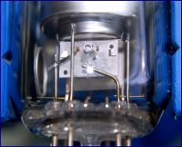
The equalising ring on the left seems to correspond to a nebulous incomplete circle at left in Les's radiograph.
What is the origin of the impacting electrons? Comparing the strong verticals in the radiograph with the vertical supports as we see them here, it seems reasonable to suppose that the electrons must have originated in the conductive metallic getter coat on the inside of the glass.
Proud Mary, Wed Feb 16 2011, 01:00PM
PD500 base internal view

The equalising ring on the left seems to correspond to a nebulous incomplete circle at left in Les's radiograph.
What is the origin of the impacting electrons? Comparing the strong verticals in the radiograph with the vertical supports as we see them here, it seems reasonable to suppose that the electrons must have originated in the conductive metallic getter coat on the inside of the glass.
Re: Vacuum Rectifiers X-rays report
plazmatron, Wed Feb 16 2011, 01:57PM
This is what appeared most confusing to me too. There appears to be no line of sight between the "cathode" and the little bundle of "anodes" at the base of the tube.
The problem with tubes like this is unpredictability of electron paths. This is evident to anyone that has seen the fluorescence on the inside of the glass caused by electron impacts. Not only do they appear quite random, but often these move around , as charges build up on the glass, electrostatically deflecting or reshaping the beams.
Hopefully the emission characteristics of the 2X2 will be a little more sane and easier to understand!
Les
plazmatron, Wed Feb 16 2011, 01:57PM
Proud Mary wrote ...
Looking at the cathode and heater assembly of PD500, it's very clear why the emission is so low - in a word, it's all boxed in by screens and shields..................
....................Wha t is the origin of the impacting electrons? Comparing the strong verticals in the radiograph with the vertical supports as we see them here, it seems reasonable to suppose that the electrons must have originated in the conductive metallic getter coat on the inside of the glass.
This is what appeared most confusing to me too. There appears to be no line of sight between the "cathode" and the little bundle of "anodes" at the base of the tube.
The problem with tubes like this is unpredictability of electron paths. This is evident to anyone that has seen the fluorescence on the inside of the glass caused by electron impacts. Not only do they appear quite random, but often these move around , as charges build up on the glass, electrostatically deflecting or reshaping the beams.
Hopefully the emission characteristics of the 2X2 will be a little more sane and easier to understand!

Les
Re: Vacuum Rectifiers X-rays report
Proud Mary, Wed Feb 16 2011, 02:27PM
On the basis that electrons won't travel any further than they have to, the only explanation for what seems distributed X-ray emission along the entire length of a vertical would be an electron source parallel to it - and hence from the getter on the glass walls.
Using PD500 as an improvised X-ray source, I think it a waste to use it in field emission mode when it is designed to operate at up to 27.5kV @ 1.6mA, and will hold off 45kV in extremis, (according to Note 2 in the Philips datasheet of 1969.) An X-ray shielding warning is printed on the glass. One can raise Va well above 27.5kV by operating the valve in starvation conditions to increase impedance and reduce Ia and so keep Wa within its 40W 'absolute max' dissipation rating. A combination of reduced heater current, and increased grid bias negative makes it possible to operate the valve at 40kV so long as flashover precautions are taken. The much greater anode current (compared with field emission) of the heated valve results in greater X-ray fluence.
Re: Vacuum Rectifiers X-rays report
Nah, Thu Feb 17 2011, 11:13PM
I'm going to ask a stupid question, why can't you use a burned out antique light bulb instead? Would the smaller surface area make a big difference in terms of xray output??
Nah, Thu Feb 17 2011, 11:13PM
I'm going to ask a stupid question, why can't you use a burned out antique light bulb instead? Would the smaller surface area make a big difference in terms of xray output??
Re: Vacuum Rectifiers X-rays report
Proud Mary, Fri Feb 18 2011, 11:49AM
Hi Nah,
thank you for your interest in this thread.
The main interest here is to try and found out why this obsolete HV thermionic diode, 2X2A, seems to produce a higher X-ray output than we would expect when compared with other common HV valve rectifiers of similar vintage. The consensus so far is that it may be due to the presence of barium, but more experiments need to be done to confirm this.
I'm not sure just what you mean by an "antique light bulb," so I'll note that X-rays are even produced by spark discharges in air at atmospheric pressure, but that relatively complex equipment is needed to detect them.
Stella
Proud Mary, Fri Feb 18 2011, 11:49AM
Nah wrote ...
I'm going to ask a stupid question, why can't you use a burned out antique light bulb instead? Would the smaller surface area make a big difference in terms of xray output??
I'm going to ask a stupid question, why can't you use a burned out antique light bulb instead? Would the smaller surface area make a big difference in terms of xray output??
Hi Nah,
thank you for your interest in this thread.
The main interest here is to try and found out why this obsolete HV thermionic diode, 2X2A, seems to produce a higher X-ray output than we would expect when compared with other common HV valve rectifiers of similar vintage. The consensus so far is that it may be due to the presence of barium, but more experiments need to be done to confirm this.
I'm not sure just what you mean by an "antique light bulb," so I'll note that X-rays are even produced by spark discharges in air at atmospheric pressure, but that relatively complex equipment is needed to detect them.
Stella
Re: Vacuum Rectifiers X-rays report
radhoo, Fri Feb 18 2011, 06:49PM
Pictures speak for themselves:
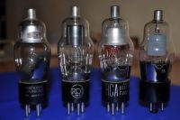
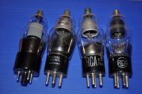
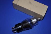
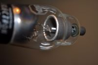
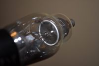
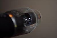
3 American 2X2 variants from different periods and the russian 2X2 I've mostly used in this thread.
I'm going to check the emission in regards to:
- the different Anode bell metal
- the different Anode Bell size
- the different oxide-tube size
- differences in internal pressure, I expect the 1954 to have a softer vacuum and so a poor performance
Regarding the points of emission. The images I took previously show the very uniform emission. Why do I keep insisting on that?
Well its because there are only a few regular geometric shapes/bodies inside the 2X2 tube and those are:
- the anode bell as a closed end cylinder
- the cathode oxide tube
In my opinion these two are responsible for the X-ray emission and the field distribution.
If the x-ray emission resulted from another point inside the tube, than I wouldn't have obtained images like these:


If the source was a single point inside the tube, then we would have seen one (or a few ) brighter spots instead this uniform illumination.
Even further, in "09.Vertical emission angle" I demonstrated the emission is given by a source at the same vertical level as the the oxide tube covering the filament.
These two observations indicate the emission results from a bombardment of the oxide tube by electrons emitted from the WHOLE inner surface of the anode bell. The shape of the two is reflected in the uniform illumination of the fluorescent screen.
Why the oxide tube and not the filament inside?
- Because the tube is a perfect cylinder. If the target was the filament, having the shape of two wires in close proximity, the resulting 360degrees X-ray images (see blue images above) wouldn't have been identical . Instead as the shape of the filament is not geometrically regulated, we would have seen more shadows vs. intense spots and not a uniform distribution of the X-ray emission field all around the tube.
Why all the bell's inside surface is an emitter?
- because the field is stronger near the center of the bell and decreases in a gradient towards the top, where : the distance to the center electrode is bigger, -or- there is not oxide on the top of the cathode tube.
Another possibility regarding the x-ray emission ,but not related to the anode/cathode shape, is that of electrons impacting the glass. As shown here: some tubes took advantage of this property to totally exclude the use of a metallic cathode target, and use glass for x-ray emission.
See the pictures I posted of the operating tube: it has a very strong blue glow.
However , there are some issues with this theory: first because the anode bell works as a shield that would block any inside emission, and than its the polarity applied to the tube. The Anode bell is negative while the internal oxide tube is positive. The electrons would take the opposed path, going towards the center and not the glass walls.
radhoo, Fri Feb 18 2011, 06:49PM
Pictures speak for themselves:


3 American 2X2 variants from different periods and the russian 2X2 I've mostly used in this thread.
I'm going to check the emission in regards to:
- the different Anode bell metal
- the different Anode Bell size
- the different oxide-tube size
- differences in internal pressure, I expect the 1954 to have a softer vacuum and so a poor performance
Regarding the points of emission. The images I took previously show the very uniform emission. Why do I keep insisting on that?
Well its because there are only a few regular geometric shapes/bodies inside the 2X2 tube and those are:
- the anode bell as a closed end cylinder
- the cathode oxide tube
In my opinion these two are responsible for the X-ray emission and the field distribution.
If the x-ray emission resulted from another point inside the tube, than I wouldn't have obtained images like these:


If the source was a single point inside the tube, then we would have seen one (or a few ) brighter spots instead this uniform illumination.
Even further, in "09.Vertical emission angle"
 I demonstrated the emission is given by a source at the same vertical level as the the oxide tube covering the filament.
These two observations indicate the emission results from a bombardment of the oxide tube by electrons emitted from the WHOLE inner surface of the anode bell. The shape of the two is reflected in the uniform illumination of the fluorescent screen.
Why the oxide tube and not the filament inside?
- Because the tube is a perfect cylinder. If the target was the filament, having the shape of two wires in close proximity, the resulting 360degrees X-ray images (see blue images above) wouldn't have been identical . Instead as the shape of the filament is not geometrically regulated, we would have seen more shadows vs. intense spots and not a uniform distribution of the X-ray emission field all around the tube.
Why all the bell's inside surface is an emitter?
- because the field is stronger near the center of the bell and decreases in a gradient towards the top, where : the distance to the center electrode is bigger, -or- there is not oxide on the top of the cathode tube.
Another possibility regarding the x-ray emission ,but not related to the anode/cathode shape, is that of electrons impacting the glass. As shown here:
 some tubes took advantage of this property to totally exclude the use of a metallic cathode target, and use glass for x-ray emission.
See the pictures I posted of the operating tube: it has a very strong blue glow.
However , there are some issues with this theory: first because the anode bell works as a shield that would block any inside emission, and than its the polarity applied to the tube. The Anode bell is negative while the internal oxide tube is positive. The electrons would take the opposed path, going towards the center and not the glass walls.
Re: Vacuum Rectifiers X-rays report
Proud Mary, Fri Feb 18 2011, 07:36PM
It's interesting to compare the Russian and American interpretations of the A-suffix ruggedized 2X2 'For applications critical as to severe shock and vibration.'
The Russians have applied a dark body radiator coating to their 2X2A anode, to reduce its temperature, and hence the heat conducted into the top cap glass seal.
They have shortened the cathode and filament assembly support rods to reduce mechanical advantage on the glass seals, but the price of this has been
the need for a heat shield to deflect radiant heat away from the glass-metal interfaces coming up from the base.
Finally, they have replaced the '4 Small Pin' base with the much more transplantable International Octal base configuration, to carry the design forward into the next generation of thermionic technology.
Re: Vacuum Rectifiers X-rays report
radhoo, Sat Feb 19 2011, 10:16PM
12. 2X2 CCCP vs. USA ??!
Note: 4 variants of the 2X2 Tube has been used. The tubes stand in vertical position. The camera has been set on a tripod, with unchanged parameters (same focus/exposure time/etc). All the tubes has been powered up in inverse polarization, using the same potential difference.
Objective: compare the x-ray emission output by using the fluorescent screen
The tubes used:
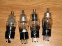
From left to the right:
The russian 2X2 (that I've used several times in this thread).
Three american 2X2 variants, the forth appears to be the oldest (manufactured in 1954)
In the same order, here are the results:
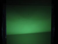
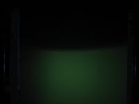

The Russian 2X2 emits the most radiation. Actually the X-ray output a few times the output of the other tubes. An impressive difference.
The setup has not been changed, extra care was taken when replacing the tubes not to change the distances / fluorescent screen position from the camera, so differences in the emission field can also be observed.
The last 2X2, from 1954 seems to have 0 x-ray output (vacuum inside changed because of age? ).
radhoo, Sat Feb 19 2011, 10:16PM
12. 2X2 CCCP vs. USA ??!
Note: 4 variants of the 2X2 Tube has been used. The tubes stand in vertical position. The camera has been set on a tripod, with unchanged parameters (same focus/exposure time/etc). All the tubes has been powered up in inverse polarization, using the same potential difference.
Objective: compare the x-ray emission output by using the fluorescent screen
The tubes used:

From left to the right:
The russian 2X2 (that I've used several times in this thread).
Three american 2X2 variants, the forth appears to be the oldest (manufactured in 1954)
In the same order, here are the results:


The Russian 2X2 emits the most radiation. Actually the X-ray output a few times the output of the other tubes. An impressive difference.
The setup has not been changed, extra care was taken when replacing the tubes not to change the distances / fluorescent screen position from the camera, so differences in the emission field can also be observed.
The last 2X2, from 1954 seems to have 0 x-ray output (vacuum inside changed because of age? ).
Re: Vacuum Rectifiers X-rays report
radhoo, Sat Feb 19 2011, 10:28PM
13. Targets
Note: the camera has been brought dangerously close to the setup, to take photographs of the electron targets:
1) In normal polarization the source is the normal central cathode , and the target the inside of the electron bell
2) In inverse polarization, the source is the inside of the electron bell, and the target the oxide cylinder covering the filament.
The 1954 American 2X2, used in inverse polarization:
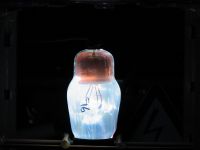
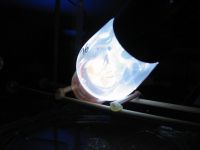
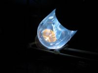
Remember, this tube has very little (if any) x-ray output. Since I used the fluorescent screen for detecting radiation, I used no dosimeter (Radex 1706) in this test scenario. The third picture has the exposure reduced, so you can see the oxide tube getting hot-red because of the electron bombardment. No other component inside the tube seems to be targeted (not even the wires supporting the oxide tube).
Another American 2X2, in inverse polarization, with the oxide tube glowing because of the electrons:
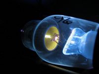
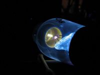
An now, the last tube again, in direct polarization. In only a few seconds (aprox. 6 seconds), the anode bell is incandescent, because now it becomes target of the electrons emitted by the central cathode:
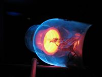
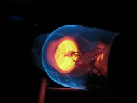
On the other hand, my tests showed that the Russian 2X2 doesn't get incandescent not even after 15 seconds!
Luckily my camera survived the dangerous proximity of the setup, and no arc-overs occurred to it.
radhoo, Sat Feb 19 2011, 10:28PM
13. Targets
Note: the camera has been brought dangerously close to the setup, to take photographs of the electron targets:
1) In normal polarization the source is the normal central cathode , and the target the inside of the electron bell
2) In inverse polarization, the source is the inside of the electron bell, and the target the oxide cylinder covering the filament.
The 1954 American 2X2, used in inverse polarization:


Remember, this tube has very little (if any) x-ray output. Since I used the fluorescent screen for detecting radiation, I used no dosimeter (Radex 1706) in this test scenario. The third picture has the exposure reduced, so you can see the oxide tube getting hot-red because of the electron bombardment. No other component inside the tube seems to be targeted (not even the wires supporting the oxide tube).
Another American 2X2, in inverse polarization, with the oxide tube glowing because of the electrons:


An now, the last tube again, in direct polarization. In only a few seconds (aprox. 6 seconds), the anode bell is incandescent, because now it becomes target of the electrons emitted by the central cathode:


On the other hand, my tests showed that the Russian 2X2 doesn't get incandescent not even after 15 seconds!
Luckily my camera survived the dangerous proximity of the setup, and no arc-overs occurred to it.
Re: Vacuum Rectifiers X-rays report
radhoo, Sat Feb 19 2011, 10:38PM
14. Pinhole camera - a Paradox?
Note: Using the Russian 2X2, a sheet of lead has been placed in front of the tube, in vertical position. In front of the hottest x-ray emission zone, a pin hole has been made in the lead sheet. The distance between the tube and the lead sheet is 6 cm. On the other side, at 4 cm distance, the fluorescent screen has been placed. So the distance between the fluorescent screen and the tube is a total of 10cm.
The camera has been brought close to the fluorescent screen and focus attempted using the super-macro setting.
The setup:
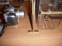
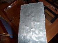
Based on my previous experiments, I would have expected the camera to record a filled spot (since I assumed we have an uniform SINGLE x-ray emitter source - the central oxide bar). Instead... :
The images have been enhanced in software. Now a lot of damage on the CCD (random pixels) also becomes visible.
Comments:
If I'm not wrong, it appears there are 2 points of emission in horizontal plane? If yes I can only think of the glass walls (left-right).
radhoo, Sat Feb 19 2011, 10:38PM
14. Pinhole camera - a Paradox?
Note: Using the Russian 2X2, a sheet of lead has been placed in front of the tube, in vertical position. In front of the hottest x-ray emission zone, a pin hole has been made in the lead sheet. The distance between the tube and the lead sheet is 6 cm. On the other side, at 4 cm distance, the fluorescent screen has been placed. So the distance between the fluorescent screen and the tube is a total of 10cm.
The camera has been brought close to the fluorescent screen and focus attempted using the super-macro setting.
The setup:


Based on my previous experiments, I would have expected the camera to record a filled spot (since I assumed we have an uniform SINGLE x-ray emitter source - the central oxide bar). Instead... :


The images have been enhanced in software. Now a lot of damage on the CCD (random pixels) also becomes visible.
Comments:
If I'm not wrong, it appears there are 2 points of emission in horizontal plane? If yes I can only think of the glass walls (left-right).
Re: Vacuum Rectifiers X-rays report
Proud Mary, Sun Feb 20 2011, 12:55AM
This is an excellent start, Radu, but there is a risk of certain assumptions and methodological errors clouding our understanding of what is happening here.
1) How does the perceived relative brightness of a fluorescent screen relate to the energy and fluence of the X-rays exciting it? What does it mean to say that one optical event is "twice as bright" as another to the human eye? Does the light output of your screen have a linear relationship to X-ray energy, and to X-ray fluence, or is it non-linear? And so on.
2) As you do not record the potential difference across the tubes, nor the current in each case, there is a chance of being seriously mislead. It is perfectly possible that the American valves had a lower impedance in field emission mode, and drew more current than your supply could deliver without a significant drop in voltage. Once this voltage falls below ~20kV, the X-radiation will be increasely attenuated by the glass envelope, but this will not stop the glass from fluorescing blue from photons striking its inner surface, as we see in your excellent pictures. This would explain why the poor X-ray emitters have the effective anode (i.e. the maker's cathode) white hot, while the good Russian tube does not have enough current flowing through it to heat the efffective anode to incandescence. (You will recall that the old TV EHT thermionic diode rectifiers only became an X-ray hazard when their heaters failed, and their impedance rose to a high value, so the full EHT voltage appeared across them)
I shall finish working on my dosimetry experiment tomorrow night, using the two Russian 2X2As I have been able to find, and so will be able to tell you the
actual dose rate in Gy/hr across 15kV - 40kV in 5kV increments. I'll post up the graphs on Monday morning.
Re: Vacuum Rectifiers X-rays report
radhoo, Sun Feb 20 2011, 10:31AM
The "fluence"/intensity of x-rays relates not to the brightness perceived, but to the exposure time needed to capture the image. It's similar to water flowing through a pipe, filling a glass, or to electric current filling a capacitor, since. Intensity is a function of time.
An event would be brighter than another, if the image as recorded by the CCD is brighter, meaning it contains at least one pixel with a higher value than all other pixels in the image we relate to.
The light brightness output of the screen can either have a linear relationship to energy or a non-linear, it's not really important, since a scale can be determined empirically by using a tube and a variable High voltage supply. For each increasing step, we would record the difference from previous frames, since X-ray emission contains the max energy in a small fraction, and all the other lower energy levels.
So do you still thing this is not doable? Your CdS+fluorescent screen dosimeter comes with a similar approach (also requiring calibration for any useful purpose).
But probably you're right, it's not good to jump to conclusions with so many uncertain premises. At least we have something new to think of and this story goes on. Speaking of something new, here is a crop of the original pinhole camera image (I selected the best image I got, from 3 attempts):
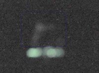
See the big image. I've selected in blue something barely visible, that attracted my attention while looking over the photos.
Too bad I didn't mark the position of the pinhole in regard to the fluorescent screen! I'll have to do this again.
LE: first at didn't want to puncture the only lead sheet I have and tried to use a 0.5mm Aluminum sheet, that made no difference, as the x-rays were passing right through it. The lead sheet was a different story: it is 1.6mm tick.
radhoo, Sun Feb 20 2011, 10:31AM
Proud Mary wrote ...
1) How does the perceived relative brightness of a fluorescent screen relate to the energy and fluence of the X-rays exciting it? What does it mean to say that one optical event is "twice as bright" as another to the human eye? Does the light output of your screen have a linear relationship to X-ray energy, and to X-ray fluence, or is it non-linear? And so on.
LE: Let's not discuss brightness in the biological context, eg. as perceived by the human eye, but use instead another sensor such as a CCD camera. By doing so we would need to quantify any image focused by the camera lens on the ccd into pixels. For simplicity we won;t use colors, but gray scale colors instead, where complete blackness would be attributed a value of 0, and white would be 255. A photon striking the LCD will create an electrical signal related to the photon initial energy, and so we will get a darker or brighter pixel (0...255). Of course there are limits to the CCDs like too much energy (>255) that the CCD won't handle (CCD blindness), but it's too early to discuss error cases. There won't be too much light to get anyway.1) How does the perceived relative brightness of a fluorescent screen relate to the energy and fluence of the X-rays exciting it? What does it mean to say that one optical event is "twice as bright" as another to the human eye? Does the light output of your screen have a linear relationship to X-ray energy, and to X-ray fluence, or is it non-linear? And so on.
The "fluence"/intensity of x-rays relates not to the brightness perceived, but to the exposure time needed to capture the image. It's similar to water flowing through a pipe, filling a glass, or to electric current filling a capacitor, since. Intensity is a function of time.
An event would be brighter than another, if the image as recorded by the CCD is brighter, meaning it contains at least one pixel with a higher value than all other pixels in the image we relate to.
The light brightness output of the screen can either have a linear relationship to energy or a non-linear, it's not really important, since a scale can be determined empirically by using a tube and a variable High voltage supply. For each increasing step, we would record the difference from previous frames, since X-ray emission contains the max energy in a small fraction, and all the other lower energy levels.
So do you still thing this is not doable? Your CdS+fluorescent screen dosimeter comes with a similar approach (also requiring calibration for any useful purpose).
But probably you're right, it's not good to jump to conclusions with so many uncertain premises. At least we have something new to think of and this story goes on. Speaking of something new, here is a crop of the original pinhole camera image (I selected the best image I got, from 3 attempts):

See the big image. I've selected in blue something barely visible, that attracted my attention while looking over the photos.
Too bad I didn't mark the position of the pinhole in regard to the fluorescent screen! I'll have to do this again.
LE: first at didn't want to puncture the only lead sheet I have and tried to use a 0.5mm Aluminum sheet, that made no difference, as the x-rays were passing right through it. The lead sheet was a different story: it is 1.6mm tick.
Re: Vacuum Rectifiers X-rays report
Proud Mary, Sun Feb 20 2011, 12:00PM
I've got to get the Sunday roast into the oven, so can only say a few words for now.
Firstly, I shall be cross if you spoil your camera, because you will be needing it.
If you are finding it difficult to get lead glass, ordinary plate glass as used in big shop windows will give significant protection to your camera at the photon energies being used in these experiments.
As to your pin-hole radiographs, do you now think that the gap between the two nebulae is an image of the gap between the two filament supply rods? If it is, then the gap should disappear if you turn the valve through 90° on its axis.
If you think the X-rays are being produced by electrons leaving the edge of the heat shield impacting on the glass - or the flashed getter, or both - then taping a narrow strip of aluminium foil round the outside of the glass on the plane of the heat shield and then connecting this to Earth should increase the x-ray fluence (if you can stop flashover, and you don't get dielectric puncture of the glass! )
Ah well, the kitchen calls!

Re: Vacuum Rectifiers X-rays report
plazmatron, Sun Feb 20 2011, 08:13PM
@ Radhoo:
your pinhole cameras performance is a lot better than I would have expected! If you manage to get hold of some thick plate glass to protect you camera as Proud Mary suggests, it may be worth making a much smaller pinhole, and trying a much longer exposure to see if you can obtain a higher resolution image.
Also kudos on the much needed comparison of the American and CCCP 2X2's I am really looking forward to trying this out now!
I will be interested to see that too!
plazmatron, Sun Feb 20 2011, 08:13PM
@ Radhoo:
your pinhole cameras performance is a lot better than I would have expected! If you manage to get hold of some thick plate glass to protect you camera as Proud Mary suggests, it may be worth making a much smaller pinhole, and trying a much longer exposure to see if you can obtain a higher resolution image.
Also kudos on the much needed comparison of the American and CCCP 2X2's I am really looking forward to trying this out now!
Proud Mary wrote ...
I shall finish working on my dosimetry experiment tomorrow night, using the two Russian 2X2As I have been able to find, and so will be able to tell you the
actual dose rate in Gy/hr across 15kV - 40kV in 5kV increments. I'll post up the graphs on Monday morning.
I shall finish working on my dosimetry experiment tomorrow night, using the two Russian 2X2As I have been able to find, and so will be able to tell you the
actual dose rate in Gy/hr across 15kV - 40kV in 5kV increments. I'll post up the graphs on Monday morning.
I will be interested to see that too!
Re: Vacuum Rectifiers X-rays report
Proud Mary, Mon Feb 21 2011, 09:25AM
Later - Monday morning events in real life have intervened!
Proud Mary, Mon Feb 21 2011, 09:25AM
plazmatron wrote ...
I will be interested to see that too!
Proud Mary wrote ...
I shall finish working on my dosimetry experiment tomorrow night, using the two Russian 2X2As I have been able to find, and so will be able to tell you the
actual dose rate in Gy/hr across 15kV - 40kV in 5kV increments. I'll post up the graphs on Monday morning.
I shall finish working on my dosimetry experiment tomorrow night, using the two Russian 2X2As I have been able to find, and so will be able to tell you the
actual dose rate in Gy/hr across 15kV - 40kV in 5kV increments. I'll post up the graphs on Monday morning.
I will be interested to see that too!
Later - Monday morning events in real life have intervened!

Re: Vacuum Rectifiers X-rays report
Proud Mary, Mon Feb 21 2011, 05:27PM
Everything always seems to take me far, far longer than I'd planned, but progress is being made!

Proud Mary, Mon Feb 21 2011, 05:27PM
Everything always seems to take me far, far longer than I'd planned, but progress is being made!


Re: Vacuum Rectifiers X-rays report
Proud Mary, Tue Feb 22 2011, 03:58PM
I should have foreseen the problems I'm now having - aside from slatternly idleness that is - and have had to construct a 40kV PSU with a stiffer output that isn't so easily pulled down when the 2X2A starts drawing current, which makes trying to draw graphs relating Ia, Va, and Gy rather like playing croquet with a flamingo and a hedgehog that keeps wandering off as the ball.

But I am sorting it out now.
Proud Mary, Tue Feb 22 2011, 03:58PM
I should have foreseen the problems I'm now having - aside from slatternly idleness that is - and have had to construct a 40kV PSU with a stiffer output that isn't so easily pulled down when the 2X2A starts drawing current, which makes trying to draw graphs relating Ia, Va, and Gy rather like playing croquet with a flamingo and a hedgehog that keeps wandering off as the ball.

But I am sorting it out now.

Re: Vacuum Rectifiers X-rays report
radhoo, Wed Feb 23 2011, 01:09PM
Les, did you get your tubes? I've just returned from the post office with my package from Gintaras (KWTubes). Love the radio-id postcards he is sending.
Stella, more problems may also be a premise for more innovative solutions, keep us posted of your progress and good luck with that!
Re: Vacuum Rectifiers X-rays report
Linas, Wed Feb 23 2011, 02:47PM

Maybe you know which x ray screen is best for experiments ? (most sensitive to x rays and have low cost)
Now thinking about this:

Linas, Wed Feb 23 2011, 02:47PM
radhoo wrote ...
Les, did you get your tubes? I've just returned from the post office with my package from Gintaras (KWTubes). Love the radio-id postcards he is sending.
What a small world, i saw Gintaras yesterday Les, did you get your tubes? I've just returned from the post office with my package from Gintaras (KWTubes). Love the radio-id postcards he is sending.

Maybe you know which x ray screen is best for experiments ? (most sensitive to x rays and have low cost)
Now thinking about this:

Re: Vacuum Rectifiers X-rays report
plazmatron, Wed Feb 23 2011, 03:02PM
No yet, I have heard from him a few days ago though, and they have been posted, so within the week I guess.
@Stella. happens to me all the time!
Les
plazmatron, Wed Feb 23 2011, 03:02PM
radhoo wrote ...
Les, did you get your tubes? I've just returned from the post office with my package from Gintaras (KWTubes). Love the radio-id postcards he is sending.
Les, did you get your tubes? I've just returned from the post office with my package from Gintaras (KWTubes). Love the radio-id postcards he is sending.
No yet, I have heard from him a few days ago though, and they have been posted, so within the week I guess.
@Stella. happens to me all the time!
Les
Re: Vacuum Rectifiers X-rays report
Proud Mary, Wed Feb 23 2011, 04:27PM
OK Radu, here's my completed 3-stage full-wave C&W module ready to drown in an oil bath. The diodes are 30kV 30mA, the vitreous anti-surge resistors 1.2kΩ, and the capacitors 0.02μF 16kV. The yellow AC input cables are 30kV copper core vehicle ignition leads (off the roll) and the output lead is RS Components 25kV EHT cable inside a flush fit silicone rubber tube. The AC input leads also have in-line anti-inrush vitreous resistors in them.
The component values and choice of parts reflect what I could find around the house, rather than what might be ideal.
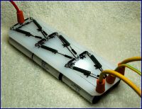
Vpk across the balanced input can be varied across about 2kV - 6.7kV to produce an output of ~12kV - ~40kV NEG. Being a total slut, I'll supply the C&W from a 4kV-0-4kV 50Hz transformer controlled by a Variac, though I shan't be able to exploit the maximum Vpk of 11kV because of the 16kV Vmax limit of the capacitors.
If, in future, I should want more than a few hundred μA for other experiments, I can run the multiplier module at a higher frequency from an inverter, when the large capacitors will really come into their own. I've made it into a HV NEG supply because I mostly work in grounded anode mode, and it makes no difference to the 2X2A tests.
And here below is a completed 2.2MΩ in-line anti-surge resistor to protect the output against spark down and flash-over. Below it is the self-adhesive heat shrink used, and a similar 1MΩ HV resistor ready to make another surge limiter for use when the voltage drop across the 2.2MΩ becomes excessive.
I will put it all together tomorrow if I can find the time.
Proud Mary, Wed Feb 23 2011, 04:27PM
radhoo wrote ...
Stella, more problems may also be a premise for more innovative solutions, keep us posted of your progress and good luck with that!
Stella, more problems may also be a premise for more innovative solutions, keep us posted of your progress and good luck with that!
OK Radu, here's my completed 3-stage full-wave C&W module ready to drown in an oil bath. The diodes are 30kV 30mA, the vitreous anti-surge resistors 1.2kΩ, and the capacitors 0.02μF 16kV. The yellow AC input cables are 30kV copper core vehicle ignition leads (off the roll) and the output lead is RS Components 25kV EHT cable inside a flush fit silicone rubber tube. The AC input leads also have in-line anti-inrush vitreous resistors in them.
The component values and choice of parts reflect what I could find around the house, rather than what might be ideal.

Vpk across the balanced input can be varied across about 2kV - 6.7kV to produce an output of ~12kV - ~40kV NEG. Being a total slut, I'll supply the C&W from a 4kV-0-4kV 50Hz transformer controlled by a Variac, though I shan't be able to exploit the maximum Vpk of 11kV because of the 16kV Vmax limit of the capacitors.
If, in future, I should want more than a few hundred μA for other experiments, I can run the multiplier module at a higher frequency from an inverter, when the large capacitors will really come into their own. I've made it into a HV NEG supply because I mostly work in grounded anode mode, and it makes no difference to the 2X2A tests.
And here below is a completed 2.2MΩ in-line anti-surge resistor to protect the output against spark down and flash-over. Below it is the self-adhesive heat shrink used, and a similar 1MΩ HV resistor ready to make another surge limiter for use when the voltage drop across the 2.2MΩ becomes excessive.

I will put it all together tomorrow if I can find the time.

Re: Vacuum Rectifiers X-rays report
Wolfram, Wed Feb 23 2011, 06:29PM
What sort of experiments? If you want max light output and don't care much about resolution, a screen from a fast/rapid x-ray cassette would be ideal. If you want maximum resolution, a screen from a mammography cassette (Agfa Mamoray, Fuji Mammo or Kodak Min-R) would be best. These have much higher resolution than regular x-ray cassettes, but they give a bit less light.
That's some very nice work Stella, looking forward to seeing your results.
And I've said it before, but your results here have been much better than what I thought was possible with these tubes, Radhoo
Wolfram, Wed Feb 23 2011, 06:29PM
Linas wrote ...

Maybe you know which x ray screen is best for experiments ? (most sensitive to x rays and have low cost)
Now thinking about this:

radhoo wrote ...
Les, did you get your tubes? I've just returned from the post office with my package from Gintaras (KWTubes). Love the radio-id postcards he is sending.
What a small world, i saw Gintaras yesterday Les, did you get your tubes? I've just returned from the post office with my package from Gintaras (KWTubes). Love the radio-id postcards he is sending.

Maybe you know which x ray screen is best for experiments ? (most sensitive to x rays and have low cost)
Now thinking about this:

What sort of experiments? If you want max light output and don't care much about resolution, a screen from a fast/rapid x-ray cassette would be ideal. If you want maximum resolution, a screen from a mammography cassette (Agfa Mamoray, Fuji Mammo or Kodak Min-R) would be best. These have much higher resolution than regular x-ray cassettes, but they give a bit less light.
That's some very nice work Stella, looking forward to seeing your results.
And I've said it before, but your results here have been much better than what I thought was possible with these tubes, Radhoo
Re: Vacuum Rectifiers X-rays report
radhoo, Thu Feb 24 2011, 10:23AM
radhoo, Thu Feb 24 2011, 10:23AM
Anders M. wrote ...
That's some very nice work Stella, looking forward to seeing your results.
Indeed the setup looks very nice.That's some very nice work Stella, looking forward to seeing your results.
Anders M. wrote ...
And I've said it before, but your results here have been much better than what I thought was possible with these tubes, Radhoo
It appears the Russian 2X2 is a very special tube, there are still a few available on Ebay for those interested (KWTubes).And I've said it before, but your results here have been much better than what I thought was possible with these tubes, Radhoo
Re: Vacuum Rectifiers X-rays report
Wolfram, Thu Feb 24 2011, 02:47PM
Very interesting experiment. Notice the figure-8 shape of the focal spot, it actually corresponds very well with this drawing.
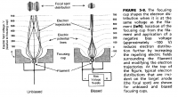
Do you have any dental x-ray tubes with a biased filament cup you could try this experiment with? It would be very interesting seeing how changing the bias voltage affected the size and shape of the focal spot.
Wolfram, Thu Feb 24 2011, 02:47PM
plazmatron wrote ...
OK the intensified pinhole camera works fine.
First off we have an image of the focal spot of a small dental x-ray tube (below).
Note, the resolution is good enough that is is obvious the spot is rectangular, corresponding to the spot etched to the anode face

OK the intensified pinhole camera works fine.
First off we have an image of the focal spot of a small dental x-ray tube (below).
Note, the resolution is good enough that is is obvious the spot is rectangular, corresponding to the spot etched to the anode face

Very interesting experiment. Notice the figure-8 shape of the focal spot, it actually corresponds very well with this drawing.

Do you have any dental x-ray tubes with a biased filament cup you could try this experiment with? It would be very interesting seeing how changing the bias voltage affected the size and shape of the focal spot.
Re: Vacuum Rectifiers X-rays report
plazmatron, Thu Feb 24 2011, 03:24PM
So it does! I have noticed this self same pattern etched into the anodes of x-ray tubes before.
Unfortunately none of the tubes I have has a biased filament cup, but it would make for an interesting future experiment for the vacuum rig
Les
plazmatron, Thu Feb 24 2011, 03:24PM
Anders M. wrote ...
Very interesting experiment. Notice the figure-8 shape of the focal spot, it actually corresponds very well with this drawing.
Do you have any dental x-ray tubes with a biased filament cup you could try this experiment with? It would be very interesting seeing how changing the bias voltage affected the size and shape of the focal spot.
So it does! I have noticed this self same pattern etched into the anodes of x-ray tubes before.
Unfortunately none of the tubes I have has a biased filament cup, but it would make for an interesting future experiment for the vacuum rig

Les
Re: Vacuum Rectifiers X-rays report
Proud Mary, Thu Feb 24 2011, 05:01PM
I've just noticed a used dental tube on fleabay UK, a buy-it-now for £20.
It looks a bit forlorn and sorry for itself, but the seller says the filament is good.
It's not my kind of thing at all, but it might be good as a starter tube for someone here, but as ever with ebay, caveat emptor!

Re: Vacuum Rectifiers X-rays report
Wolfram, Thu Feb 24 2011, 05:16PM
That tube is not in bad condition, the glass is a bit dirty and a pin is bent, but aside from that it looks fine. It actually looks to be of the biased filament cup variety, as it has three pins with solder on them.
Wolfram, Thu Feb 24 2011, 05:16PM
Proud Mary wrote ...
I've just noticed a used dental tube on fleabay UK, a buy-it-now for £20.
It looks a bit forlorn and sorry for itself, but the seller says the filament is good.
It's not my kind of thing at all, but it might be good as a starter tube for someone here, but as ever with ebay, caveat emptor!

I've just noticed a used dental tube on fleabay UK, a buy-it-now for £20.
It looks a bit forlorn and sorry for itself, but the seller says the filament is good.
It's not my kind of thing at all, but it might be good as a starter tube for someone here, but as ever with ebay, caveat emptor!

That tube is not in bad condition, the glass is a bit dirty and a pin is bent, but aside from that it looks fine. It actually looks to be of the biased filament cup variety, as it has three pins with solder on them.
Re: Vacuum Rectifiers X-rays report
radhoo, Thu Feb 24 2011, 05:39PM
Stella, I just remembered: for my HV multiplier supply I use a 20KOhm HV limiting resistor (taken from an old TV).
Anders, from what book is the page you've scanned? How should we interpret the pinhole image results in the case of the 2x2?
Nice tube on Ebay. Are you guys interested in it, or can I try my luck?
Re: Vacuum Rectifiers X-rays report
Proud Mary, Thu Feb 24 2011, 05:42PM
Get it before it goes, Radu! If you don't, someone else will at that price.
Proud Mary, Thu Feb 24 2011, 05:42PM
radhoo wrote ...
Nice tube on Ebay. Are you guys interested in it, or can I try my luck?
Nice tube on Ebay. Are you guys interested in it, or can I try my luck?
Get it before it goes, Radu! If you don't, someone else will at that price.
Re: Vacuum Rectifiers X-rays report
Wolfram, Fri Feb 25 2011, 10:45AM
The scan is from "The Essential Physics of Medical Imaging, Second Edition" , this is an excellent book about these kinds of things. It even contains energy response curves for (Gd2O2S-based) fluorescent screens and all sorts of other information that's hard to find anywhere else. I've read a few medical books on radiography, and most of them concentrate on patient positioning and image interpretation, they usually contain very little useful information, but this book is an exception to that rule, and I can recommend it to anyone with an interest in x-rays.
When we're on the subject of good x-ray books, I can also recommend "X-ray Studies" from General Electric, which is freely available on archive.org . It's a collection of papers on hot-cathode x-ray tubes and related subjects. It includes W.D. Coolidge's original paper on the hot-cathode x-ray tube and some follow-up papers, and a lot of other interesting documents.
I'm not sure how I would interpret your 2X2 pinhole images. As you say it seems very paradoxical. Maybe Plazmatron's experiments will clear things up, when he receives his 2X2s.
Wolfram, Fri Feb 25 2011, 10:45AM
radhoo wrote ...
Anders, from what book is the page you've scanned? How should we interpret the pinhole image results in the case of the 2x2?
Anders, from what book is the page you've scanned? How should we interpret the pinhole image results in the case of the 2x2?
The scan is from "The Essential Physics of Medical Imaging, Second Edition" , this is an excellent book about these kinds of things. It even contains energy response curves for (Gd2O2S-based) fluorescent screens and all sorts of other information that's hard to find anywhere else. I've read a few medical books on radiography, and most of them concentrate on patient positioning and image interpretation, they usually contain very little useful information, but this book is an exception to that rule, and I can recommend it to anyone with an interest in x-rays.
When we're on the subject of good x-ray books, I can also recommend "X-ray Studies" from General Electric, which is freely available on archive.org
 . It's a collection of papers on hot-cathode x-ray tubes and related subjects. It includes W.D. Coolidge's original paper on the hot-cathode x-ray tube and some follow-up papers, and a lot of other interesting documents.
I'm not sure how I would interpret your 2X2 pinhole images. As you say it seems very paradoxical. Maybe Plazmatron's experiments will clear things up, when he receives his 2X2s.
Re: Vacuum Rectifiers X-rays report
plazmatron, Sat Feb 26 2011, 12:13AM
My 2X2's turned up today, thanks to Gintaras!
So first off I had to test this out! The radiation this little tube produces is totally amazing! It will actually conduct mA's if pushed hard enough, but of course this will quickly destroy it.
So I set up the pinhole camera, and produced a pair of images that settles where the radiation comes from.
Nearly all of the x-rays come from..................the heat shield, making the edge of the anode bell the most likely emitter of electrons. (I had had incorrectly surmised the entire surface was emitting electrons in the direction of the heater)
The photo below is a pinhole image looking down onto the heat shield.
The top surface of the shield is obviously a bright emitter of x-rays. The black structure in the middle is the heater and cathode support obscuring the x-rays.
Note underneath the heat shield some of the glass support can be seen, (note also the hole for evacuation!) There are slots cut in the heat shield, so electron beams make their way through, and impinge on the glass support, causing parts of it to emit x-rays.
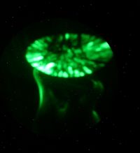
Below is another view of the 2X2 this time looking up towards the underneath of the heat shield.
Note the original heated cathode is a poor emitter of x-rays, and is actually emitting less x-rays than the glass support is! Note also that the underside of the heat shield is visible since the x-rays produced at the top surface make their way though.
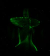
Les
plazmatron, Sat Feb 26 2011, 12:13AM
My 2X2's turned up today, thanks to Gintaras!
So first off I had to test this out! The radiation this little tube produces is totally amazing! It will actually conduct mA's if pushed hard enough, but of course this will quickly destroy it.
So I set up the pinhole camera, and produced a pair of images that settles where the radiation comes from.
Nearly all of the x-rays come from..................the heat shield, making the edge of the anode bell the most likely emitter of electrons. (I had had incorrectly surmised the entire surface was emitting electrons in the direction of the heater)
The photo below is a pinhole image looking down onto the heat shield.
The top surface of the shield is obviously a bright emitter of x-rays. The black structure in the middle is the heater and cathode support obscuring the x-rays.
Note underneath the heat shield some of the glass support can be seen, (note also the hole for evacuation!) There are slots cut in the heat shield, so electron beams make their way through, and impinge on the glass support, causing parts of it to emit x-rays.

Below is another view of the 2X2 this time looking up towards the underneath of the heat shield.
Note the original heated cathode is a poor emitter of x-rays, and is actually emitting less x-rays than the glass support is! Note also that the underside of the heat shield is visible since the x-rays produced at the top surface make their way though.

Les
Re: Vacuum Rectifiers X-rays report
Proud Mary, Sat Feb 26 2011, 12:58AM
What super images, Les. Well done!
Didn't someone identify the heat shield as the probable X-ray emitter earlier in the thread?
The radiation on the underside of the shield must inevitably contain the characteristic spectra of the metallic elements used in the shield, including the pressed barium alloy 'pill', in addition to any target transmission shoot-through.
Anyway, that's all absolutely capital, and I'm looking forward to making my own experimental contribution this weekend, with dose rate measurements for the 2X2A.
I've potted the C&W module, so now only have the experimental jig to improvise out of lab scaffolding and stock lead laminates.
Proud Mary, Sat Feb 26 2011, 12:58AM
What super images, Les. Well done!

Didn't someone identify the heat shield as the probable X-ray emitter earlier in the thread?
The radiation on the underside of the shield must inevitably contain the characteristic spectra of the metallic elements used in the shield, including the pressed barium alloy 'pill', in addition to any target transmission shoot-through.
Anyway, that's all absolutely capital, and I'm looking forward to making my own experimental contribution this weekend, with dose rate measurements for the 2X2A.
I've potted the C&W module, so now only have the experimental jig to improvise out of lab scaffolding and stock lead laminates.
Re: Vacuum Rectifiers X-rays report
plazmatron, Sat Feb 26 2011, 01:17AM
Thanks! I thought someone had mentioned it too, but I cant find the comment in the thread, I had thought it was you. Maybe it was Radhoo?
All of this is coming together quite nicely.
Absolutely. Do you know anyone with Sprectrometer?
The tube I tried drew whatever current my HV supply would throw at it. Yours being somewhat beefier than mine, will need quite a bit of ballast resistance to stop the tube vapourising!
Les
plazmatron, Sat Feb 26 2011, 01:17AM
Proud Mary wrote ...
What super images, Les. Well done!
Didn't someone identify the heat shield as the probable X-ray emitter earlier in the thread?
What super images, Les. Well done!

Didn't someone identify the heat shield as the probable X-ray emitter earlier in the thread?
Thanks! I thought someone had mentioned it too, but I cant find the comment in the thread, I had thought it was you. Maybe it was Radhoo?
All of this is coming together quite nicely.
Proud Mary wrote ...
The radiation on the underside of the shield must inevitably contain the characteristic spectra of the metallic elements used in the shield, including the pressed barium alloy 'pill', in addition to any target transmission shoot-through.
The radiation on the underside of the shield must inevitably contain the characteristic spectra of the metallic elements used in the shield, including the pressed barium alloy 'pill', in addition to any target transmission shoot-through.
Absolutely. Do you know anyone with Sprectrometer?

Proud Mary wrote ...
I've potted the C&W module, so now only have the experimental jig to improvise out of lab scaffolding and
I've potted the C&W module, so now only have the experimental jig to improvise out of lab scaffolding and
The tube I tried drew whatever current my HV supply would throw at it. Yours being somewhat beefier than mine, will need quite a bit of ballast resistance to stop the tube vapourising!

Les
Re: Vacuum Rectifiers X-rays report
Proud Mary, Sat Feb 26 2011, 01:50AM
I first proposed the shielding plate as the source on
Tue Jan 18 2011, 04:02PM
when I wrote:
Thinking about the concentric shadow surrounding the anode shadow in your radiograph, I wonder if it can be the longitudinal shadow of the anode bell from X-ray photons produced by field electron impacts on the circular shielding plate?
It certainly is an interesting feature worth investigating. If you have a good magnet, and place it near the shielding plate it might cause sufficient disturbance of the field emission electrons to show up on the radiograph
Which started me off on making a detailed investigation of the heat shield.
Now, Les, if you were to locate a strong magnet abreast of the heat shield, and then take another pin hole radiograph, we may see something of interest.
I think I can feel an energy dispersal moment coming on:
Proud Mary, Sat Feb 26 2011, 01:50AM
plazmatron wrote ...
Thanks! I thought someone had mentioned it too, but I cant find the comment in the thread, I had thought it was you. Maybe it was Radhoo?
All of this is coming together quite nicely.
Proud Mary wrote ...
What super images, Les. Well done!
Didn't someone identify the heat shield as the probable X-ray emitter earlier in the thread?
What super images, Les. Well done!

Didn't someone identify the heat shield as the probable X-ray emitter earlier in the thread?
Thanks! I thought someone had mentioned it too, but I cant find the comment in the thread, I had thought it was you. Maybe it was Radhoo?
All of this is coming together quite nicely.
I first proposed the shielding plate as the source on
Tue Jan 18 2011, 04:02PM
when I wrote:
Thinking about the concentric shadow surrounding the anode shadow in your radiograph, I wonder if it can be the longitudinal shadow of the anode bell from X-ray photons produced by field electron impacts on the circular shielding plate?
It certainly is an interesting feature worth investigating. If you have a good magnet, and place it near the shielding plate it might cause sufficient disturbance of the field emission electrons to show up on the radiograph
Which started me off on making a detailed investigation of the heat shield.
Now, Les, if you were to locate a strong magnet abreast of the heat shield, and then take another pin hole radiograph, we may see something of interest.
plazmatron wrote ...
Absolutely. Do you know anyone with Sprectrometer?
Proud Mary wrote ...
The radiation on the underside of the shield must inevitably contain the characteristic spectra of the metallic elements used in the shield, including the pressed barium alloy 'pill', in addition to any target transmission shoot-through.
The radiation on the underside of the shield must inevitably contain the characteristic spectra of the metallic elements used in the shield, including the pressed barium alloy 'pill', in addition to any target transmission shoot-through.
Absolutely. Do you know anyone with Sprectrometer?

I think I can feel an energy dispersal moment coming on:

Re: Vacuum Rectifiers X-rays report
radhoo, Sat Feb 26 2011, 01:58PM
The shielding plate seems to be a good answer for several observed aspects:
- why do we get two concentric shadow rings, when the tube is placed with the anode perpendicular to the fluorescent screen (one would be the anode cap, the other could be from the anode bell)
- the uniform distribution of the x-ray emission, all around the tube
- the good performance at 45 degrees
- the different performance between the Russian variant and the USA variant (that doesn't have a heat shield)
EDIT: for some reason I missed Les' post so here are a few comments:
What surprised me event further, is that even if the glass envelope can get warm after a few radiographs (a few sets of 15sec usage), I've seen no metal part getting incandescent (in the Russian Variant).
What have you used to record those pictures with such an excellent quality?
ps: I got the tube on ebay. hope will perform better than the 2X2s :)
ps2: Les' images with some additional software enhacement. I would really like to know more on how these photos where made. Great job, so many details visible!
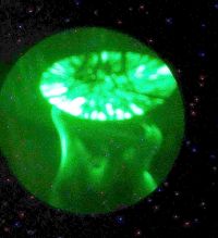
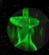
ps3: Still if the shield is a target for the electrons coming from above, how come we get so much radiation in the shield's plane?
radhoo, Sat Feb 26 2011, 01:58PM
The shielding plate seems to be a good answer for several observed aspects:
- why do we get two concentric shadow rings, when the tube is placed with the anode perpendicular to the fluorescent screen (one would be the anode cap, the other could be from the anode bell)
- the uniform distribution of the x-ray emission, all around the tube
- the good performance at 45 degrees
- the different performance between the Russian variant and the USA variant (that doesn't have a heat shield)
EDIT: for some reason I missed Les' post so here are a few comments:
plazmatron wrote ...
It will actually conduct mA's if pushed hard enough, but of course this will quickly destroy it.
My 100uAmp-meter went off-scale in normal polarization, and I was using a limiting resistor.It will actually conduct mA's if pushed hard enough, but of course this will quickly destroy it.
What surprised me event further, is that even if the glass envelope can get warm after a few radiographs (a few sets of 15sec usage), I've seen no metal part getting incandescent (in the Russian Variant).
plazmatron wrote ...
Nearly all of the x-rays come from..................the heat shield, making the edge of the anode bell the most likely emitter of electrons. (I had had incorrectly surmised the entire surface was emitting electrons in the direction of the heater)
Well, who would have had imagined such a trajectory for the electrons? Nearly all of the x-rays come from..................the heat shield, making the edge of the anode bell the most likely emitter of electrons. (I had had incorrectly surmised the entire surface was emitting electrons in the direction of the heater)
plazmatron wrote ...
Below is another view of the 2X2 this time looking up towards the underneath of the heat shield.
Note the original heated cathode is a poor emitter of x-rays, and is actually emitting less x-rays than the glass support is! Note also that the underside of the heat shield is visible since the x-rays produced at the top surface make their way though.
Can you post a photo showing your setup for this experiment? Below is another view of the 2X2 this time looking up towards the underneath of the heat shield.
Note the original heated cathode is a poor emitter of x-rays, and is actually emitting less x-rays than the glass support is! Note also that the underside of the heat shield is visible since the x-rays produced at the top surface make their way though.
What have you used to record those pictures with such an excellent quality?
ps: I got the tube on ebay. hope will perform better than the 2X2s :)
ps2: Les' images with some additional software enhacement. I would really like to know more on how these photos where made. Great job, so many details visible!


ps3: Still if the shield is a target for the electrons coming from above, how come we get so much radiation in the shield's plane?

Re: Vacuum Rectifiers X-rays report
Proud Mary, Sat Feb 26 2011, 02:45PM
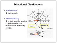
Proud Mary, Sat Feb 26 2011, 02:45PM
radhoo wrote ...
Still if the shield is a target for the electrons coming from above, how come we get so much radiation in the shield's plane?
Still if the shield is a target for the electrons coming from above, how come we get so much radiation in the shield's plane?

Re: Vacuum Rectifiers X-rays report
uzzors2k, Sat Feb 26 2011, 03:09PM
This is amazing! I've been following this thread since it started, and have to say I'm impressed by what you guys and gals have discovered. I'm tinkering away at my own setup right now, and hope to try some American 2X2A tubes I have.
Your pinhole images are fascinating Leslie, you're using an intensifier tube to see this if I'm not mistaken? I'm interested in the details of the pinhole itself too. Reading about pinhole cameras it would seem we need a micrometer sized hole to get focused images, if using a practical focal length.
Oh, and to help aid visualization of the x-ray source, here's Radu's enhanced images beside Stella's heat-shield pics. The detail is incredible!
uzzors2k, Sat Feb 26 2011, 03:09PM
This is amazing!
 I've been following this thread since it started, and have to say I'm impressed by what you guys and gals have discovered. I'm tinkering away at my own setup right now, and hope to try some American 2X2A tubes I have.
Your pinhole images are fascinating Leslie, you're using an intensifier tube to see this if I'm not mistaken? I'm interested in the details of the pinhole itself too. Reading about pinhole cameras it would seem we need a micrometer sized hole to get focused images, if using a practical focal length.
Oh, and to help aid visualization of the x-ray source, here's Radu's enhanced images beside Stella's heat-shield pics. The detail is incredible!
Re: Vacuum Rectifiers X-rays report
plazmatron, Sat Feb 26 2011, 04:17PM
I will take some photos at the beginning of the week, as I am away till Monday night.
The apparatus consists of one of my very sensitive x-ray Fluoroscopes described here, (except this version uses a Generation II tube),and a lead pinhole camera assembly.
An 8 inch long truncated cone was fabricated from lead sheet. The tip of the cone is flat, with a large hole drilled in it to permit mounting a pinhole of any size. . The pinhole is about 0.05mm across, and was made in a separate thin piece of lead.
This is simply mounted on the front of the fluoroscope, and pointed at the x-ray source. The output screen in viewable in real time to dark adapted eyes, but the digital camera requires a 15s exposure to produce a bright enough image from the screen.
The cone of the pinhole camera is made so long as to permit some decent magnification of the x-ray sources.
Next week I will take some real close ups of the anode, and try and setup the webcam to take some very long exposures, to see if the weaker emissions the tube can be imaged in this way.
Les
plazmatron, Sat Feb 26 2011, 04:17PM
radhoo wrote ...
Can you post a photo showing your setup for this experiment?
What have you used to record those pictures with such an excellent quality?
ps2: Les' images with some additional software enhacement. I would really like to know more on how these photos where made. Great job, so many details visible!
Can you post a photo showing your setup for this experiment?
What have you used to record those pictures with such an excellent quality?
ps2: Les' images with some additional software enhacement. I would really like to know more on how these photos where made. Great job, so many details visible!
I will take some photos at the beginning of the week, as I am away till Monday night.
The apparatus consists of one of my very sensitive x-ray Fluoroscopes described here, (except this version uses a Generation II tube),and a lead pinhole camera assembly.
An 8 inch long truncated cone was fabricated from lead sheet. The tip of the cone is flat, with a large hole drilled in it to permit mounting a pinhole of any size. . The pinhole is about 0.05mm across, and was made in a separate thin piece of lead.
This is simply mounted on the front of the fluoroscope, and pointed at the x-ray source. The output screen in viewable in real time to dark adapted eyes, but the digital camera requires a 15s exposure to produce a bright enough image from the screen.
The cone of the pinhole camera is made so long as to permit some decent magnification of the x-ray sources.
Next week I will take some real close ups of the anode, and try and setup the webcam to take some very long exposures, to see if the weaker emissions the tube can be imaged in this way.
Les
Re: Vacuum Rectifiers X-rays report
radhoo, Sat Feb 26 2011, 04:21PM
Hi Eirik!
Thanks for joining in!
I'm a bit confused: Are you saying Les is using an intensifier tube? I assume he is also using a fluorescent screen of some kind to filter the regular light (there is plenty while the tube is powered on) from the x-rays. Les, we'd like to see your setup.
LE: cross-posting: ok, looking forward to see your pictures. thanks for the details!
The American 2X2 might not be very good at this, I've used 2 different tubes with not much output (there are some pics a few posts above).
Stella, thanks for the graph a few comments:
- it shows a point-like target
- bremsstrahlung radiation goes in the electron direction, so if the target is the shield, this is not the cause for the abundant x-rays
- which leaves: the K X-rays (now I wonder what the shield is made of: you've mentioned it was magnetic some time ago). So for the point-like target , the graph shows a sphere like distribution all around the target (I see a small circle).
One thing that doesn't seem right with the current shield target idea:
The target is white-hot! The shield doesn't even get red...
radhoo, Sat Feb 26 2011, 04:21PM
Hi Eirik!
Thanks for joining in!
I'm a bit confused: Are you saying Les is using an intensifier tube? I assume he is also using a fluorescent screen of some kind to filter the regular light (there is plenty while the tube is powered on) from the x-rays. Les, we'd like to see your setup.
LE: cross-posting: ok, looking forward to see your pictures. thanks for the details!
The American 2X2 might not be very good at this, I've used 2 different tubes with not much output (there are some pics a few posts above).
Stella, thanks for the graph a few comments:
- it shows a point-like target
- bremsstrahlung radiation goes in the electron direction, so if the target is the shield, this is not the cause for the abundant x-rays
- which leaves: the K X-rays (now I wonder what the shield is made of: you've mentioned it was magnetic some time ago). So for the point-like target , the graph shows a sphere like distribution all around the target (I see a small circle).
One thing that doesn't seem right with the current shield target idea:

The target is white-hot! The shield doesn't even get red...
Re: Vacuum Rectifiers X-rays report
radhoo, Sat Feb 26 2011, 04:48PM
On another closer look, the shield might be affected too:
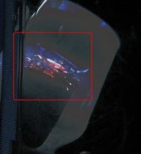
But I will need to take better photos of that.
radhoo, Sat Feb 26 2011, 04:48PM
On another closer look, the shield might be affected too:

But I will need to take better photos of that.
Re: Vacuum Rectifiers X-rays report
Proud Mary, Sat Feb 26 2011, 04:55PM
I think perhaps I should have added a few words of explanation to the graph.
You will notice that at 50keV, there is significant radiation at 90° to the electron beam, but at 500keV the bremmstrahlung follows the direction of the electron beam much more closely. i.e. the tendency of the bremmstrahlung to follow the electron beam direction is energy dependent.
Now, if you have 40kV on your anode, about 1% of the X-rays produced will have an energy of 40keV, and all the rest will have less, down the lowest energy that can transmitted by the glass envelope (say 15keV) tending to become more and more isotropic with decreasing energy.
And to these increasingly isotropic bremmstrahlung can be added the isotropic characteristic rays of the elements in the target.
Your observations about heat dissipated in the anode seem to confuse X-ray energy with tube current and with fluence. You could have 100kV across a micro field emission tube which drew but 1μA, for a total power of 100mW. It would emit a tiny amount of 100keV rays, but their fluence - quantity of photons per square metre - would be very low indeed, and the tube would not get significantly warm.
Conversely, you can find Be window XRD tubes with just 10kV on the anode that gobble up 1kW or more and need high pressure water cooling.
On a separate note: FILTRATION
Filtration with Al, Cu, or Ag foils may improve the resolution of the pin-hole images.
Proud Mary, Sat Feb 26 2011, 04:55PM
radhoo wrote ...
Stella, thanks for the graph a few comments:
- it shows a point-like target
- bremsstrahlung radiation goes in the electron direction, so if the target is the shield, this is not the cause for the abundant x-rays
- which leaves: the K X-rays (now I wonder what the shield is made of: you've mentioned it was magnetic some time ago). So for the point-like target , the graph shows a sphere like distribution all around the target (I see a small circle).
One thing that doesn't seem right with the current shield target idea:
This is how an electron bombardment target looks like at 50KV pd:

White-hot!
The shield doesn't even get red...
Stella, thanks for the graph a few comments:
- it shows a point-like target
- bremsstrahlung radiation goes in the electron direction, so if the target is the shield, this is not the cause for the abundant x-rays
- which leaves: the K X-rays (now I wonder what the shield is made of: you've mentioned it was magnetic some time ago). So for the point-like target , the graph shows a sphere like distribution all around the target (I see a small circle).
One thing that doesn't seem right with the current shield target idea:
This is how an electron bombardment target looks like at 50KV pd:

White-hot!
The shield doesn't even get red...
I think perhaps I should have added a few words of explanation to the graph.
You will notice that at 50keV, there is significant radiation at 90° to the electron beam, but at 500keV the bremmstrahlung follows the direction of the electron beam much more closely. i.e. the tendency of the bremmstrahlung to follow the electron beam direction is energy dependent.
Now, if you have 40kV on your anode, about 1% of the X-rays produced will have an energy of 40keV, and all the rest will have less, down the lowest energy that can transmitted by the glass envelope (say 15keV) tending to become more and more isotropic with decreasing energy.
And to these increasingly isotropic bremmstrahlung can be added the isotropic characteristic rays of the elements in the target.
Your observations about heat dissipated in the anode seem to confuse X-ray energy with tube current and with fluence. You could have 100kV across a micro field emission tube which drew but 1μA, for a total power of 100mW. It would emit a tiny amount of 100keV rays, but their fluence - quantity of photons per square metre - would be very low indeed, and the tube would not get significantly warm.
Conversely, you can find Be window XRD tubes with just 10kV on the anode that gobble up 1kW or more and need high pressure water cooling.
On a separate note: FILTRATION
Filtration with Al, Cu, or Ag foils may improve the resolution of the pin-hole images.
Re: Vacuum Rectifiers X-rays report
plazmatron, Sat Feb 26 2011, 05:27PM
Thanks and yes, its a GenII image intensifier tube with GADOX scintillator bonded to the face plate, like my fluoroscopes. The pinhole is 0.05mm diameter. Micron sized would be better, but even with a system gain of around 40,000 very long exposures would be needed. (a project for next week).
Oh and thanks for the comparison pics post, it certainly clarifies what is being observed here.
It certainly looks white hot, however that coating is brilliantly fluorescent under the impact of electrons!
Note the comparatively dark uncoated region at the end of the heater.
If you really push the tube the shield can be raised to yellow heat under the impact of electrons.
The fluoroscope is already filtered with 0.5mm Aluminium. A smaller hole and longer exposure is what is needed now.
Les
plazmatron, Sat Feb 26 2011, 05:27PM
Uzzors wrote ...
Your pinhole images are fascinating Leslie, you're using an intensifier tube to see this if I'm not mistaken? I'm interested in the details of the pinhole itself too. Reading about pinhole cameras it would seem we need a micrometer sized hole to get focused images, if using a practical focal length.
Your pinhole images are fascinating Leslie, you're using an intensifier tube to see this if I'm not mistaken? I'm interested in the details of the pinhole itself too. Reading about pinhole cameras it would seem we need a micrometer sized hole to get focused images, if using a practical focal length.
Thanks and yes, its a GenII image intensifier tube with GADOX scintillator bonded to the face plate, like my fluoroscopes. The pinhole is 0.05mm diameter. Micron sized would be better, but even with a system gain of around 40,000 very long exposures would be needed. (a project for next week).
Oh and thanks for the comparison pics post, it certainly clarifies what is being observed here.

radhoo wrote ...
White-hot!
The shield doesn't even get red...
White-hot!
The shield doesn't even get red...
It certainly looks white hot, however that coating is brilliantly fluorescent under the impact of electrons!
Note the comparatively dark uncoated region at the end of the heater.
If you really push the tube the shield can be raised to yellow heat under the impact of electrons.
Proud Mary wrote ...
On a separate note: FILTRATION
Filtration with Al, Cu, or Ag foils may improve the resolution of the pin-hole images.
On a separate note: FILTRATION
Filtration with Al, Cu, or Ag foils may improve the resolution of the pin-hole images.
The fluoroscope is already filtered with 0.5mm Aluminium. A smaller hole and longer exposure is what is needed now.
Les
Re: Vacuum Rectifiers X-rays report
radhoo, Sat Feb 26 2011, 07:11PM
Perhaps I wasn't clear, my idea was a bit different: we have different dissipation on the filament as compared to the relatively bigger shield, but still it would have been nice to actually see the shield being struck by electrons and emanating heat.
About the shield, I would like to see it getting yellow, but I guess the filament would melt first.
Still for such an emission intensity, I would have expected the target to become more visible while under electron fire.
radhoo, Sat Feb 26 2011, 07:11PM
Proud Mary wrote ...
Your observations about heat dissipated in the anode seem to confuse X-ray energy with tube current and with fluence. You could have 100kV across a micro field emission tube which drew but 1μA, for a total power of 100mW. It would emit a tiny amount of 100keV rays, but their fluence - quantity of photons per square metre - would be very low indeed, and the tube would not get significantly warm.
Conversely, you can find Be window XRD tubes with just 10kV on the anode that gobble up 1kW or more and need high pressure water cooling.
What you're saying here is P=UxI and that more electron intensity will produce more x-ray intensity "fluence?", while the potential difference is responsible for the energy and penetration power of the x-ray photons. The x-ray intensity is what follows the inverse square law (since it's radiant energy) and we're all using it to keep us safe while experimenting. etc.Your observations about heat dissipated in the anode seem to confuse X-ray energy with tube current and with fluence. You could have 100kV across a micro field emission tube which drew but 1μA, for a total power of 100mW. It would emit a tiny amount of 100keV rays, but their fluence - quantity of photons per square metre - would be very low indeed, and the tube would not get significantly warm.
Conversely, you can find Be window XRD tubes with just 10kV on the anode that gobble up 1kW or more and need high pressure water cooling.
Perhaps I wasn't clear, my idea was a bit different: we have different dissipation on the filament as compared to the relatively bigger shield, but still it would have been nice to actually see the shield being struck by electrons and emanating heat.
plazmatron wrote ...
It certainly looks white hot, however that coating is brilliantly fluorescent under the impact of electrons!
Note the comparatively dark uncoated region at the end of the heater.
If you really push the tube the shield can be raised to yellow heat under the impact of electrons.
Yes, it looks white hot, and when you unplug the supply you will see it get orange, then red, brown and black.It certainly looks white hot, however that coating is brilliantly fluorescent under the impact of electrons!
Note the comparatively dark uncoated region at the end of the heater.
If you really push the tube the shield can be raised to yellow heat under the impact of electrons.
About the shield, I would like to see it getting yellow, but I guess the filament would melt first.
Still for such an emission intensity, I would have expected the target to become more visible while under electron fire.
Re: Vacuum Rectifiers X-rays report
Steve Conner, Sat Feb 26 2011, 07:12PM
Excellent pics, Les! This has been the most interesting thread in a long time.
I can recommend the X-Ray Studies book, that's where I read about the pinhole camera technique.
Steve Conner, Sat Feb 26 2011, 07:12PM
Excellent pics, Les! This has been the most interesting thread in a long time.

I can recommend the X-Ray Studies book, that's where I read about the pinhole camera technique.
Re: Vacuum Rectifiers X-rays report
radhoo, Sat Feb 26 2011, 07:22PM
Les, can you try to photograph the filament area as well? You can get a few mm of it, if you rotate the tube in the right position.
LE: In regards to this: , here is a little experiment. Pictures are self explanatory:
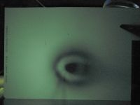
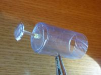
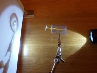
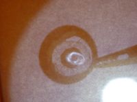
It shows that we get the same circular shadows if we place the source of light where the shield is.
So in case of x-ray emissions, this would produce the 2 concentric shadows we've seen on the first tests with the 2X2.
Comments?
radhoo, Sat Feb 26 2011, 07:22PM
Les, can you try to photograph the filament area as well? You can get a few mm of it, if you rotate the tube in the right position.
LE: In regards to this:
 , here is a little experiment. Pictures are self explanatory:


It shows that we get the same circular shadows if we place the source of light where the shield is.
So in case of x-ray emissions, this would produce the 2 concentric shadows we've seen on the first tests with the 2X2.
Comments?
Re: Vacuum Rectifiers X-rays report
Proud Mary, Sat Feb 26 2011, 10:20PM
There is no parabolic path of bremmstrahlung.
The graphical curves are a way of illustrating the ratio of X-ray photons departing at any particular angle relative to the incident electron beam.
The lower the energy of the electrons, the more the X-ray photons tend towards an isotropic distribution - i.e. go in all directions of a sphere.
The higher the energy, the more the photons will tend to continue in the same direction as the incident electrons.
At the relatively low energy levels of these experiments - between about 15keV - 40keV - there will be considerable photon emission at all angles related to the incident electron beam.
A Google search for "Bremsstrahlung angular distribution" will lead you to more detailed explanations of this phenomenon.
Proud Mary, Sat Feb 26 2011, 10:20PM
radhoo wrote ...
I don't think the parabolic path of the bremmstrahlung is what I've photographed
I don't think the parabolic path of the bremmstrahlung is what I've photographed
There is no parabolic path of bremmstrahlung.
The graphical curves are a way of illustrating the ratio of X-ray photons departing at any particular angle relative to the incident electron beam.
The lower the energy of the electrons, the more the X-ray photons tend towards an isotropic distribution - i.e. go in all directions of a sphere.
The higher the energy, the more the photons will tend to continue in the same direction as the incident electrons.
At the relatively low energy levels of these experiments - between about 15keV - 40keV - there will be considerable photon emission at all angles related to the incident electron beam.
A Google search for "Bremsstrahlung angular distribution" will lead you to more detailed explanations of this phenomenon.

Re: Vacuum Rectifiers X-rays report
radhoo, Sun Feb 27 2011, 09:35AM
Thanks for the clarification.
So this means I might see changes in the fluorescent band as recorded here...

...if I vary the voltage across the tube. With my current setup I should be able to go from 10KV to 70KV (with more stress on the components).
As a remark to , the fluorescent screen shows a more illuminated area to the left and some shadows in the right part. If the shield is the target, this might be related to the angle the shield is placed at (not perfectly parallel to the base, and so not parallel to the fluorescent screen)
radhoo, Sun Feb 27 2011, 09:35AM
Thanks for the clarification.
So this means I might see changes in the fluorescent band as recorded here...

...if I vary the voltage across the tube. With my current setup I should be able to go from 10KV to 70KV (with more stress on the components).
As a remark to
 , the fluorescent screen shows a more illuminated area to the left and some shadows in the right part. If the shield is the target, this might be related to the angle the shield is placed at (not perfectly parallel to the base, and so not parallel to the fluorescent screen)
Re: Vacuum Rectifiers X-rays report
Proud Mary, Sun Feb 27 2011, 12:26PM
By George, he's got it!
Now as for your fluorescent bands, as you say, Radu, we may see a redistribution of the light intensity as you vary the tube voltage but the tube geometry, the non-linear energy response of both the phosphors and the human eye, the filtration of the rays by the glass envelope, etc, may make the effect hard to see across our voltage range.
So - when it comes to your turn to explain the angular distribution of bremmstrahlung, you only need mention the Koch and Motz bremsstrahlung double differential cross-section to see people's eyes glaze over, and bring the conversation to a speedy end!
I'm just getting the Sunday roast into the oven now, but hope that I might have some preliminary results tonight, if I'm quick, or by tomorrow anyway.
Proud Mary, Sun Feb 27 2011, 12:26PM
radhoo wrote ...
Thanks for the clarification.
So this means I might see changes in the fluorescent band as recorded here...

...if I vary the voltage across the tube. With my current setup I should be able to go from 10KV to 70KV (with more stress on the components).
As a remark to , the fluorescent screen shows a more illuminated area to the left and some shadows in the right part. If the shield is the target, this might be related to the angle the shield is placed at (not perfectly parallel to the base, and so not parallel to the fluorescent screen)
Thanks for the clarification.
So this means I might see changes in the fluorescent band as recorded here...

...if I vary the voltage across the tube. With my current setup I should be able to go from 10KV to 70KV (with more stress on the components).
As a remark to
 , the fluorescent screen shows a more illuminated area to the left and some shadows in the right part. If the shield is the target, this might be related to the angle the shield is placed at (not perfectly parallel to the base, and so not parallel to the fluorescent screen)
By George, he's got it!

Now as for your fluorescent bands, as you say, Radu, we may see a redistribution of the light intensity as you vary the tube voltage but the tube geometry, the non-linear energy response of both the phosphors and the human eye, the filtration of the rays by the glass envelope, etc, may make the effect hard to see across our voltage range.
So - when it comes to your turn to explain the angular distribution of bremmstrahlung, you only need mention the Koch and Motz bremsstrahlung double differential cross-section to see people's eyes glaze over, and bring the conversation to a speedy end!

I'm just getting the Sunday roast into the oven now, but hope that I might have some preliminary results tonight, if I'm quick, or by tomorrow anyway.
Re: Vacuum Rectifiers X-rays report
Wolfram, Sun Feb 27 2011, 11:16PM
It definitely will. I'm really looking forward to seeing your results when you receive it.
Don't give up on the 2X2s though, there a lot of good science being done in this thread.
Wolfram, Sun Feb 27 2011, 11:16PM
radhoo wrote ...
ps: I got the tube on ebay. hope will perform better than the 2X2s :)
ps: I got the tube on ebay. hope will perform better than the 2X2s :)
It definitely will. I'm really looking forward to seeing your results when you receive it.
Don't give up on the 2X2s though, there a lot of good science being done in this thread.
Re: Vacuum Rectifiers X-rays report
radhoo, Mon Feb 28 2011, 10:58AM
radhoo, Mon Feb 28 2011, 10:58AM
Anders M. wrote ...
Don't give up on the 2X2s though, there a lot of good science being done in this thread.
I won't. As per the thread's title, I still need to come with a final enclosure/setup for the tube, easy to deploy and use. Eirik might finish his first, maybe he'll post some pictures here later.Don't give up on the 2X2s though, there a lot of good science being done in this thread.
Re: Vacuum Rectifiers X-rays report
Proud Mary, Mon Feb 28 2011, 09:43PM
Is it a samovar? Is it a funeral urn for Chernobyl victims?
Just when I thought I'd be getting round to making some measurements, various shortfalls in the shielding regime became apparent, so I ended up spending my spare time making this:
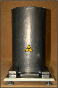
2X2A Project: Baseplate and Shielding Assembly
I riveted 1.8mm lead sheet onto a length of 20cm dia. MDPE sewage pipe, which wasn't easy to cut square. The Pb joint is lapped together, and further sealed with self-adhesive Pb tape. The thick dielectric lining will hopefully reduce the incidence of unwelcome streamers trying to find a weakness in the EHT insulation.
Progress all the same!
Proud Mary, Mon Feb 28 2011, 09:43PM
Is it a samovar? Is it a funeral urn for Chernobyl victims?
Just when I thought I'd be getting round to making some measurements, various shortfalls in the shielding regime became apparent, so I ended up spending my spare time making this:

2X2A Project: Baseplate and Shielding Assembly
I riveted 1.8mm lead sheet onto a length of 20cm dia. MDPE sewage pipe, which wasn't easy to cut square. The Pb joint is lapped together, and further sealed with self-adhesive Pb tape. The thick dielectric lining will hopefully reduce the incidence of unwelcome streamers trying to find a weakness in the EHT insulation.
Progress all the same!
Re: Vacuum Rectifiers X-rays report
plazmatron, Tue Mar 01 2011, 05:33PM
Thanks, I will check that out!
For those interested in the pics of the pinhole camera (its really not that exciting to look at though):

Above is the lead cone that fits onto the intensifier assembly.
The tip of the cone is truncated to mount the pinhole. The pinhole is made from a thinner piece of lead, and is simply taped in place.
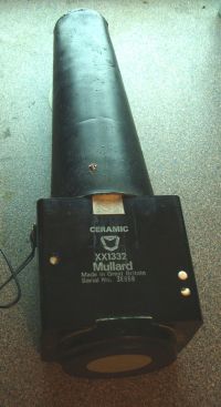
The intensified fluoroscope is a Mullard (now Phillips) XX1332, with Gd2O2S:Tb scintillator bonded to its large 50mm diameter faceplate.
The cone sits neatly on the front. I still need to make a suitable mount for it, so I can set it up on a tripod for long exposures, I expect I will have some more pinhole pics by the end of the week.
Les
plazmatron, Tue Mar 01 2011, 05:33PM
Steve McConner wrote ...
Excellent pics, Les! This has been the most interesting thread in a long time.
I can recommend the X-Ray Studies book, that's where I read about the pinhole camera technique.
Excellent pics, Les! This has been the most interesting thread in a long time.

I can recommend the X-Ray Studies book, that's where I read about the pinhole camera technique.
Thanks, I will check that out!
For those interested in the pics of the pinhole camera (its really not that exciting to look at though):

Above is the lead cone that fits onto the intensifier assembly.

The tip of the cone is truncated to mount the pinhole. The pinhole is made from a thinner piece of lead, and is simply taped in place.

The intensified fluoroscope is a Mullard (now Phillips) XX1332, with Gd2O2S:Tb scintillator bonded to its large 50mm diameter faceplate.
The cone sits neatly on the front. I still need to make a suitable mount for it, so I can set it up on a tripod for long exposures, I expect I will have some more pinhole pics by the end of the week.
Les
Re: Vacuum Rectifiers X-rays report
Mads Barnkob, Tue Mar 01 2011, 08:28PM
I just wanted to say that this has turned out as a real quality thread with massive and exciting information in a field that I know little about!
Keep up the good work :)
Mads Barnkob, Tue Mar 01 2011, 08:28PM
I just wanted to say that this has turned out as a real quality thread with massive and exciting information in a field that I know little about!
Keep up the good work :)
Re: Vacuum Rectifiers X-rays report
radhoo, Tue Mar 01 2011, 08:36PM
Les, thanks for posting those pictures.
radhoo, Tue Mar 01 2011, 08:36PM
Proud Mary wrote ...
I riveted 1.8mm lead sheet onto a length of 20cm dia. MDPE sewage pipe, which wasn't easy to cut square. The Pb joint is lapped together, and further sealed with self-adhesive Pb tape. The thick dielectric lining will hopefully reduce the incidence of unwelcome streamers trying to find a weakness in the EHT insulation.
No need for gym when you move that thing around the house. Very nice setup!I riveted 1.8mm lead sheet onto a length of 20cm dia. MDPE sewage pipe, which wasn't easy to cut square. The Pb joint is lapped together, and further sealed with self-adhesive Pb tape. The thick dielectric lining will hopefully reduce the incidence of unwelcome streamers trying to find a weakness in the EHT insulation.
Les, thanks for posting those pictures.
Re: Vacuum Rectifiers X-rays report
Proud Mary, Tue Mar 01 2011, 10:27PM
You know me by now, Radu - even the smallest indication above background outside the shield and I'll worry away at it and won't proceed further until the leak is stopped. Cable glands need special thought.
Proud Mary, Tue Mar 01 2011, 10:27PM
radhoo wrote ...
Proud Mary wrote ...
I riveted 1.8mm lead sheet onto a length of 20cm dia. MDPE sewage pipe, which wasn't easy to cut square. The Pb joint is lapped together, and further sealed with self-adhesive Pb tape. The thick dielectric lining will hopefully reduce the incidence of unwelcome streamers trying to find a weakness in the EHT insulation.
No need for gym when you move that thing around the house. Very nice setup!I riveted 1.8mm lead sheet onto a length of 20cm dia. MDPE sewage pipe, which wasn't easy to cut square. The Pb joint is lapped together, and further sealed with self-adhesive Pb tape. The thick dielectric lining will hopefully reduce the incidence of unwelcome streamers trying to find a weakness in the EHT insulation.
You know me by now, Radu - even the smallest indication above background outside the shield and I'll worry away at it and won't proceed further until the leak is stopped. Cable glands need special thought.
Re: Vacuum Rectifiers X-rays report
plazmatron, Fri Mar 11 2011, 10:45PM
Sorry for the delay regarding more pics, and the vacuum testing, but I am getting there! It been a busy week
I have already prepared a tube for the vacuum rig (removed it from its base, and carefully cut open and polished the sealing stem), and noted that the getter on the inside of the glass pretty much vanishes once the tube is up to air (as opposed to tuning milky white). Any ideas why?
Stella, how is your setup coming along?
Les
plazmatron, Fri Mar 11 2011, 10:45PM
Sorry for the delay regarding more pics, and the vacuum testing, but I am getting there! It been a busy week

I have already prepared a tube for the vacuum rig (removed it from its base, and carefully cut open and polished the sealing stem), and noted that the getter on the inside of the glass pretty much vanishes once the tube is up to air (as opposed to tuning milky white). Any ideas why?
Stella, how is your setup coming along?
Les
Re: Vacuum Rectifiers X-rays report
Proud Mary, Fri Mar 11 2011, 11:32PM
Between baking bread and making great quantities of goulash, I think I'll be able to bring everything together this weekend coming.
I've given a little thought to the geometry of the setup. In the light of your recent demonstration that the heat shield was the major X-ray source, I've decided to place the longitudinal axis of the valve at the apex of an equilateral triangle such that the pancake ionisation chamber is irradiated by a 60° segment across its 75mm width at a depth 10mm below the top surface - i.e. at the half-height of the chamber.
Proud Mary, Fri Mar 11 2011, 11:32PM
plazmatron wrote ...
Stella, how is your setup coming along?
Stella, how is your setup coming along?
Between baking bread and making great quantities of goulash, I think I'll be able to bring everything together this weekend coming.

I've given a little thought to the geometry of the setup. In the light of your recent demonstration that the heat shield was the major X-ray source, I've decided to place the longitudinal axis of the valve at the apex of an equilateral triangle such that the pancake ionisation chamber is irradiated by a 60° segment across its 75mm width at a depth 10mm below the top surface - i.e. at the half-height of the chamber.
Re: Vacuum Rectifiers X-rays report
Proud Mary, Sun Mar 13 2011, 03:17PM
2X2A Inverted Mode Measurement Findings
The findings will go on in fits and starts throughout the day as edits to this post.
X-ray emission becomes statistically significant - 10% over background - at 13.5kV, with 100mm between source and detector.
Radiation tools: ZP1430 mica end window GM tube, modified Mini Instruments Mini Monitor output pulses to Black Star Nova 2400 counter-timer.
Voltage measurement: Meter Unit Type 100, 0- 18.5kV electrostatic.
________________________________________________ __________________________________________________ __
Measurements using calibrated Fluke Victoreen Rad-Check Plus, Model 06-526, with ionisation chamber 30cc.
Energy response is ± 5% across 15kV - 65kV. Electrometer drift is 5 - 10µGy/minute typical.
Full specification is here:
Cathode axis of 2x2A 40mm above ionisation chamber half-height.
Voltages are measured directly across the tube via a 1000:1 divider. (1G/1.11M into 10M DVM)
Current is measured by a protected mirror scale moving coil microammeter in the effective cathode line (i.e. the original anode)
The effective anode is held at Earth potential, and the effective cathode at HV negative.
Integration time for all readings is 10 mins.
18kV 11uA 0.00033 Gy
18kV 12uA 0.00034 Gy
18kV 14uA 0.00035 Gy
Dose rate averaged over one hour at 18kV = 2.04 mGy/hr
19kV 21uA 0.00059 Gy
19kV 21uA 0.00060 Gy
19kV 22uA 0.00061 Gy
Dose rate averaged over one hour at 19kV = 3.6 mGy/hr
20kV 44uA 0.00190 Gy
20kV 46uA 0.00200 Gy
20kV 47uA 0.00210 Gy
Dose rate averaged over one hour at 20kV = 12 mGy/hr
21kV 61uA 0.00353 Gy
21kV 64uA 0.00269 Gy
21kV 60uA 0.00351 Gy
Dose rate averaged over one hour at 21kV = 19 mGy/hr
22kV 105uA 0.01056 Gy
22kV 102uA 0.01047 Gy
22kV 106uA 0.01055 Gy
Dose rate averaged over one hour at 22kV = 63 mGy/hr
For these next readings, I had to change to a cathode current meter of lower resolution (10uA divisions), and have made only one reading per kilovolt at this stage.
23kV 160uA 0.0152 Gy
Dose rate averaged over one hour at 23kV = 91 mGy/hr
24kV 190uA 0.0194 Gy
Dose rate averaged over one hour at 24kV = 116 mGy/hr
That's it for today, though I might put up some images and diagrams later if I can find the energy.
Note the remarkable jump in X-ray output between 21 kV and 22 kV - a phenomenon needing investigation
Proud Mary, Sun Mar 13 2011, 03:17PM
2X2A Inverted Mode Measurement Findings
The findings will go on in fits and starts throughout the day as edits to this post.
X-ray emission becomes statistically significant - 10% over background - at 13.5kV, with 100mm between source and detector.
Radiation tools: ZP1430 mica end window GM tube, modified Mini Instruments Mini Monitor output pulses to Black Star Nova 2400 counter-timer.
Voltage measurement: Meter Unit Type 100, 0- 18.5kV electrostatic.
________________________________________________ __________________________________________________ __
Measurements using calibrated Fluke Victoreen Rad-Check Plus, Model 06-526, with ionisation chamber 30cc.
Energy response is ± 5% across 15kV - 65kV. Electrometer drift is 5 - 10µGy/minute typical.
Full specification is here:

Cathode axis of 2x2A 40mm above ionisation chamber half-height.
Voltages are measured directly across the tube via a 1000:1 divider. (1G/1.11M into 10M DVM)
Current is measured by a protected mirror scale moving coil microammeter in the effective cathode line (i.e. the original anode)
The effective anode is held at Earth potential, and the effective cathode at HV negative.
Integration time for all readings is 10 mins.
18kV 11uA 0.00033 Gy
18kV 12uA 0.00034 Gy
18kV 14uA 0.00035 Gy
Dose rate averaged over one hour at 18kV = 2.04 mGy/hr
19kV 21uA 0.00059 Gy
19kV 21uA 0.00060 Gy
19kV 22uA 0.00061 Gy
Dose rate averaged over one hour at 19kV = 3.6 mGy/hr
20kV 44uA 0.00190 Gy
20kV 46uA 0.00200 Gy
20kV 47uA 0.00210 Gy
Dose rate averaged over one hour at 20kV = 12 mGy/hr
21kV 61uA 0.00353 Gy
21kV 64uA 0.00269 Gy
21kV 60uA 0.00351 Gy
Dose rate averaged over one hour at 21kV = 19 mGy/hr
22kV 105uA 0.01056 Gy
22kV 102uA 0.01047 Gy
22kV 106uA 0.01055 Gy
Dose rate averaged over one hour at 22kV = 63 mGy/hr
For these next readings, I had to change to a cathode current meter of lower resolution (10uA divisions), and have made only one reading per kilovolt at this stage.
23kV 160uA 0.0152 Gy
Dose rate averaged over one hour at 23kV = 91 mGy/hr
24kV 190uA 0.0194 Gy
Dose rate averaged over one hour at 24kV = 116 mGy/hr
That's it for today, though I might put up some images and diagrams later if I can find the energy.
Note the remarkable jump in X-ray output between 21 kV and 22 kV - a phenomenon needing investigation
Re: Vacuum Rectifiers X-rays report
Proud Mary, Wed Mar 16 2011, 04:07PM
2X2A Inverted Mode Measurement Findings
Part Two - 25kV to 30kV
25kV 500μA 227 mGy/hr
I am not happy with this measurement because:
1. I could only measure the dose for 4 mins, so as not to exceed the dosimeter's maximum reading (after which it re-sets)
2. The current climbed rapidly over the 4 mins and reached full scale 500μA where it stuck when current was removed, a sign that it had wanted to go higher. (restored to use by a light tap)
3. Anode voltage had fallen to 21.6kV after the 4 mins, as a protest against too much current being drawn. I see what Les meant when he wrote of 2X2A taking all the current he could give it.
What's a girl to do? I can replace the 2.2MΩ safety resistor between the PSU and the tube with a 910kΩ 40kV type to reduce the voltage drop across it - but this may just encourage the 2X2A to guzzle even more current.
Anyway, I have to replace the 500μA moving coil meter with a 1mA type and increase the distance between the tube and the ionization chamber before I can carry on.
Re: Vacuum Rectifiers X-rays report
Proud Mary, Wed Mar 16 2011, 05:06PM
2X2A Inverted Mode Measurement Findings
With 1000uA meter: At 25kV almost exactly 1mA was drawn, so 2.2kV was dropped across the 2.2MΩ safety resistor. My variac was wound up to the maximum and my dog's breakfast of a power supply could deliver no more!
I'm having no difficulty at all in resisting the temptation to over-stretch my PSU. With instabilities setting in, and the tube temperature rising steeply, trying to push it further would just be an expensive waste of good parts, time and money. Failure of something can't be much further down the road.
I have to make some paprika dumplings now, which will give me time to decide in which direction to go next.
Errata
For some reason, I assumed that 1mA was where the meter needle came to a halt, but I now see that the current had exceeded 1mA, and was stopped by the end of the scale.
I'll have to sort out some nichrome wire to make a shunt, as I don't have a 5mA FSD moving coil meter, and wouldn't risk a DVM in such an unruly circuit.
Re: Vacuum Rectifiers X-rays report
Proud Mary, Wed Mar 16 2011, 07:41PM
A 500uA 100Ω panel meter now turned into a 5mA one by means of an 11Ω shunt, I found that the meter read only the barest increment over 1mA with the HT turned up to 26kV.
Proud Mary, Wed Mar 16 2011, 07:41PM
A 500uA 100Ω panel meter now turned into a 5mA one by means of an 11Ω shunt, I found that the meter read only the barest increment over 1mA with the HT turned up to 26kV.
Re: Vacuum Rectifiers X-rays report
radhoo, Sat Mar 19 2011, 10:12AM
Keep the measurements coming! I'd like to see some readings over 50KV.
LE: for X-rays the Gray results numerically equal to the Sievert. Might be an useful observation when comparing the emissions above with various values found in other sources (dental x-ray dose, CT scan, etc).
* Living near a nuclear power station: 0.0001–0.01 mSv/year
* Cosmic radiation (from sky) at sea level: 0.24 mSv/year
* Terrestrial radiation (from ground): 0.28 mSv/year
* Natural radiation in the human body: 0.40 mSv/year
* Average individual background radiation dose: 2 mSv/year; 1.5 mSv/year for Australians, 3.0 mSv/year for Americans
* New York-Tokyo flights for airline crew: 9 mSv/year
* Atmospheric sources (mostly radon): 2 mSv/year
* Total average radiation dose for Americans: 6.2 mSv/year
* Current average limit for nuclear workers: 20 mSv/year
* Lowest clearly carcinogenic level: 100 mSv/year
* Elevated limit for workers during Fukushima emergency: 250 mSv/year
Acute radiation:
* 0 – 0.25 Sv (0 - 250 mSv): None
* 0.25 – 1 Sv (250 - 1000 mSv): Some people feel nausea and loss of appetite; bone marrow, lymph nodes, spleen damaged.
...
Some common examples:
* Dental radiography: 0.005 mSv
* Mammogram: 3 mSv
* Brain CT scan: 0.8–5 mSv
* Chest CT scan: 6–18 mSv
* Gastrointestinal series X-ray investigation: 14 mSv
And some uncommon (sense) examples:
* International Commission on Radiological Protection recommended limit for volunteers averting major nuclear escalation: 500 mSv
* International Commission on Radiological Protection recommended limit for volunteers rescuing lives or preventing serious injuries: 1000 mSv
radhoo, Sat Mar 19 2011, 10:12AM
Proud Mary wrote ...
I've given a little thought to the geometry of the setup. In the light of your recent demonstration that the heat shield was the major X-ray source, I've decided to place the longitudinal axis of the valve at the apex of an equilateral triangle such that the pancake ionisation chamber is irradiated by a 60° segment across its 75mm width at a depth 10mm below the top surface - i.e. at the half-height of the chamber.
Would be extremely helpful to add a few pictures/diagrams for all geometry related tests, but also for your measurements (V/A) (even some hand made sketches), and if I'm not asking too much a photo of the entire setup - Since the users here speak tens of languages, pictures are extremely valuable.I've given a little thought to the geometry of the setup. In the light of your recent demonstration that the heat shield was the major X-ray source, I've decided to place the longitudinal axis of the valve at the apex of an equilateral triangle such that the pancake ionisation chamber is irradiated by a 60° segment across its 75mm width at a depth 10mm below the top surface - i.e. at the half-height of the chamber.
Keep the measurements coming! I'd like to see some readings over 50KV.
LE: for X-rays the Gray results numerically equal to the Sievert. Might be an useful observation when comparing the emissions above with various values found in other sources (dental x-ray dose, CT scan, etc).
* Living near a nuclear power station: 0.0001–0.01 mSv/year
* Cosmic radiation (from sky) at sea level: 0.24 mSv/year
* Terrestrial radiation (from ground): 0.28 mSv/year
* Natural radiation in the human body: 0.40 mSv/year
* Average individual background radiation dose: 2 mSv/year; 1.5 mSv/year for Australians, 3.0 mSv/year for Americans
* New York-Tokyo flights for airline crew: 9 mSv/year
* Atmospheric sources (mostly radon): 2 mSv/year
* Total average radiation dose for Americans: 6.2 mSv/year
* Current average limit for nuclear workers: 20 mSv/year
* Lowest clearly carcinogenic level: 100 mSv/year
* Elevated limit for workers during Fukushima emergency: 250 mSv/year
Acute radiation:
* 0 – 0.25 Sv (0 - 250 mSv): None
* 0.25 – 1 Sv (250 - 1000 mSv): Some people feel nausea and loss of appetite; bone marrow, lymph nodes, spleen damaged.
...
Some common examples:
* Dental radiography: 0.005 mSv
* Mammogram: 3 mSv
* Brain CT scan: 0.8–5 mSv
* Chest CT scan: 6–18 mSv
* Gastrointestinal series X-ray investigation: 14 mSv
And some uncommon (sense) examples:
* International Commission on Radiological Protection recommended limit for volunteers averting major nuclear escalation: 500 mSv
* International Commission on Radiological Protection recommended limit for volunteers rescuing lives or preventing serious injuries: 1000 mSv
Re: Vacuum Rectifiers X-rays report
Proud Mary, Sat Mar 19 2011, 11:42AM
Radu, I hope I shall be able to spare four or five hours tomorrow - Sunday - and hope to do the X-ray output and current measurements for 25 - 30kV, and take some pictures for you. With the last run it took me about an hour to do each kV. (Great quantities of tea are needed! )
)
It would not be correct to use Sievert units in our calculations. While the Weighting Factor ("W") for X-ray photons is 1, such that 1 Gy = 1 Sv for X-rays, the Sievert is a unit used in the radiobiology of living systems, with which our experiments are not concerned. (But if we were to make a risk assessment of the experiments, then we would use the Sievert.)
Have you tried out your new dental tube yet? Don't blow that filament!
Proud Mary, Sat Mar 19 2011, 11:42AM
Radu, I hope I shall be able to spare four or five hours tomorrow - Sunday - and hope to do the X-ray output and current measurements for 25 - 30kV, and take some pictures for you. With the last run it took me about an hour to do each kV. (Great quantities of tea are needed!
 )
)It would not be correct to use Sievert units in our calculations. While the Weighting Factor ("W") for X-ray photons is 1, such that 1 Gy = 1 Sv for X-rays, the Sievert is a unit used in the radiobiology of living systems, with which our experiments are not concerned. (But if we were to make a risk assessment of the experiments, then we would use the Sievert.)
Have you tried out your new dental tube yet? Don't blow that filament!

Re: Vacuum Rectifiers X-rays report
radhoo, Sat Mar 19 2011, 12:08PM
radhoo, Sat Mar 19 2011, 12:08PM
Proud Mary wrote ...
Have you tried out your new dental tube yet? Don't blow that filament!
Not yet, but I'll be careful :)Have you tried out your new dental tube yet? Don't blow that filament!

Re: Vacuum Rectifiers X-rays report
Proud Mary, Sat Mar 19 2011, 02:26PM
For grounded anode tubes, where the heater supply must be 'floating,' I use up to 3 x 1.2V 9 AH NiMH cells or 2 x 2V 8AH lead acid acid, in series with a CCCP ceramic 5Ω 100W variable resistor to set the desired filament voltage. Not 'hi-tech' but it works very well, and cannot be killed by rogue spikes. It also has good intrinsic safety, because the batteries will die and stop further X-ray production if the apparatus is left running unattended for any length of time.
For grounded cathode circuits, I have found the variable voltage regulator LM338K very good for providing 1.2V - 3.0V, at up to 5A, the usual range needed for XRF and XRD tube filaments.
Proud Mary, Sat Mar 19 2011, 02:26PM
radhoo wrote ...
Proud Mary wrote ...
Have you tried out your new dental tube yet? Don't blow that filament!
Not yet, but I'll be careful :)Have you tried out your new dental tube yet? Don't blow that filament!

For grounded anode tubes, where the heater supply must be 'floating,' I use up to 3 x 1.2V 9 AH NiMH cells or 2 x 2V 8AH lead acid acid, in series with a CCCP ceramic 5Ω 100W variable resistor to set the desired filament voltage. Not 'hi-tech' but it works very well, and cannot be killed by rogue spikes. It also has good intrinsic safety, because the batteries will die and stop further X-ray production if the apparatus is left running unattended for any length of time.
For grounded cathode circuits, I have found the variable voltage regulator LM338K very good for providing 1.2V - 3.0V, at up to 5A, the usual range needed for XRF and XRD tube filaments.
Re: Vacuum Rectifiers X-rays report
Proud Mary, Sun Mar 20 2011, 10:33PM
UNDER CONSTRUCTION
2X2A Test Rig
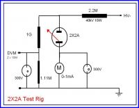
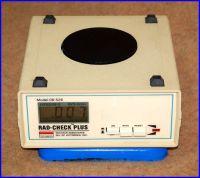
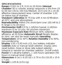
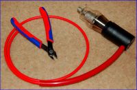
The red inner wire is RS Components 25kV EHT cable. The thick outer insulation is silicone rubber.
The black casing is a 35mm film can, a tight push fit onto the 2X2A base.
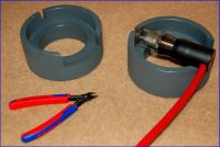
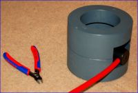
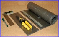
This is Code 4 - meaning 1.8mm thick - rolled lead sheet.
According to the British Sheet Lead Association: "In the UK, rolled lead sheet is the only lead sheet for building made to a British Standard – BSEN 12588:2006 Rolled Lead Sheet for Building Purposes. This specifies thickness and chemical composition to produce a consistent microstructure, which provides the required resistance to creep and thermal fatigue. The standard provides guidelines for length and width and stipulates that the sheet shall be free from inclusions and laminations. For building purposes, rolled lead sheet is available in Codes 3-8 thickness range 1.32mm to 3.55mm (+5% measured at any one point) and from widths 150mm to 2400mm."
Codes 3 and 4 are the only thicknesses I've ever seen offered for sale in builders' merchants, but I'm sure the dedicated rolled lead enthusiast could winkle out some Code 8 - the backbreaking 3.55mm - and carry it off on a forklift trolley to great applause!
The attenuation of 50keV X-ray photons (my maximum) by 1.8mm Pb sheet is 7.6E-8
I used Araldite Industrial Slow Epoxy adhesive to glue the lead sheet to the GRP form. I chose a slow setting glue to give me the longest working time
while I positioned the clamps.
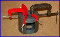
You can never have too many clamps!
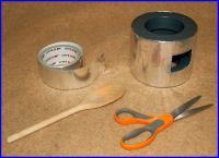
I used self-adhesive aluminium tape as an environmental barrier over the Pb sheet, and used the back of a wooden spoon as a burnisher to reduce wrinkles and blisters of trapped air.
I turned the raw edge of the cut lead over onto the top of the form by gentle tapping with a rubber mallet.
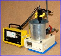
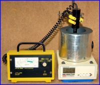
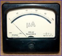
I use this large Soviet 100μA moving coil meter to measure the cathode current.
It has an internal resistance of 370Ω, so I shunt it with a 41Ω 10x multiplier when I want it to read 1mA.
I've placed a gas discharge safety gap in parallel with the meter, to stop it becoming live if it should fail open circuit.
Proud Mary, Sun Mar 20 2011, 10:33PM
UNDER CONSTRUCTION
2X2A Test Rig


The red inner wire is RS Components 25kV EHT cable. The thick outer insulation is silicone rubber.
The black casing is a 35mm film can, a tight push fit onto the 2X2A base.


This is Code 4 - meaning 1.8mm thick - rolled lead sheet.
According to the British Sheet Lead Association: "In the UK, rolled lead sheet is the only lead sheet for building made to a British Standard – BSEN 12588:2006 Rolled Lead Sheet for Building Purposes. This specifies thickness and chemical composition to produce a consistent microstructure, which provides the required resistance to creep and thermal fatigue. The standard provides guidelines for length and width and stipulates that the sheet shall be free from inclusions and laminations. For building purposes, rolled lead sheet is available in Codes 3-8 thickness range 1.32mm to 3.55mm (+5% measured at any one point) and from widths 150mm to 2400mm."
Codes 3 and 4 are the only thicknesses I've ever seen offered for sale in builders' merchants, but I'm sure the dedicated rolled lead enthusiast could winkle out some Code 8 - the backbreaking 3.55mm - and carry it off on a forklift trolley to great applause!

The attenuation of 50keV X-ray photons (my maximum) by 1.8mm Pb sheet is 7.6E-8

I used Araldite Industrial Slow Epoxy adhesive to glue the lead sheet to the GRP form. I chose a slow setting glue to give me the longest working time
while I positioned the clamps.

You can never have too many clamps!

I used self-adhesive aluminium tape as an environmental barrier over the Pb sheet, and used the back of a wooden spoon as a burnisher to reduce wrinkles and blisters of trapped air.
I turned the raw edge of the cut lead over onto the top of the form by gentle tapping with a rubber mallet.


I use this large Soviet 100μA moving coil meter to measure the cathode current.
It has an internal resistance of 370Ω, so I shunt it with a 41Ω 10x multiplier when I want it to read 1mA.
I've placed a gas discharge safety gap in parallel with the meter, to stop it becoming live if it should fail open circuit.
Re: Vacuum Rectifiers X-rays report
Patrick, Sun Mar 20 2011, 10:49PM
You guys are building such cool stuff !!! (Though, I hope you all dont die.) I wish I understood more of the radioactive phyics stuff.
Is that fat red wire HV+ ? where is your ground?
EDIT: Proud Mary I see you too are a user of the aluminum tape !
Patrick, Sun Mar 20 2011, 10:49PM
You guys are building such cool stuff !!! (Though, I hope you all dont die.) I wish I understood more of the radioactive phyics stuff.
Is that fat red wire HV+ ? where is your ground?
EDIT: Proud Mary I see you too are a user of the aluminum tape !
Re: Vacuum Rectifiers X-rays report
Proud Mary, Mon Mar 21 2011, 12:49AM
You can't have too much metal tape! I also have rolls of stainless steel, copper, and even self-adhesive lead.
Here, I'm using the aluminium tape as an environmental barrier over the 1.8mm Pb sheet. I used the back of the wooden spoon to burnish the aluminium and get out all the wrinkles and air bubbles out of it.
Proud Mary, Mon Mar 21 2011, 12:49AM
Patrick wrote ...
You guys are building such cool stuff !!! (Though, I hope you all dont die.) I wish I understood more of the radioactive phyics stuff.
Is that fat red wire HV+ ? where is your ground?
EDIT: Proud Mary I see you too are a user of the aluminum tape !
You guys are building such cool stuff !!! (Though, I hope you all dont die.) I wish I understood more of the radioactive phyics stuff.
Is that fat red wire HV+ ? where is your ground?
EDIT: Proud Mary I see you too are a user of the aluminum tape !
You can't have too much metal tape!
 I also have rolls of stainless steel, copper, and even self-adhesive lead.
Here, I'm using the aluminium tape as an environmental barrier over the 1.8mm Pb sheet. I used the back of the wooden spoon to burnish the aluminium and get out all the wrinkles and air bubbles out of it.
Re: Vacuum Rectifiers X-rays report
Patrick, Mon Mar 21 2011, 01:13AM
where is your ground to complement that fat red wire?
Patrick, Mon Mar 21 2011, 01:13AM
where is your ground to complement that fat red wire?
Re: Vacuum Rectifiers X-rays report
Proud Mary, Mon Mar 21 2011, 09:18AM
It exits the shield through a small hole almost diametrically opposite to the HV- window. But for the small voltage drop across the moving coil meter, it is effectively at Earth potential.
Proud Mary, Mon Mar 21 2011, 09:18AM
Patrick wrote ...
where is your ground to complement that fat red wire?
where is your ground to complement that fat red wire?
It exits the shield through a small hole almost diametrically opposite to the HV- window. But for the small voltage drop across the moving coil meter, it is effectively at Earth potential.
Re: Vacuum Rectifiers X-rays report
radhoo, Mon Mar 21 2011, 12:27PM
Extremely nice setup! Thanks for taking the time to post all these details.
radhoo, Mon Mar 21 2011, 12:27PM
Extremely nice setup! Thanks for taking the time to post all these details.
Re: Vacuum Rectifiers X-rays report
Proud Mary, Mon Mar 21 2011, 12:48PM
We've all received such kind and generous comments in this thread, that it makes the effort really worthwhile.
I haven't finished my Test Rig Setup post above, and will add more pictures and a commentary over the next few days.
Also, I found a box of assorted EHT rectifier and shunt stabiliser triodes in the shed, so will do some tests on them too.
Proud Mary, Mon Mar 21 2011, 12:48PM
radhoo wrote ...
Extremely nice setup! Thanks for taking the time to post all these details.
Extremely nice setup! Thanks for taking the time to post all these details.
We've all received such kind and generous comments in this thread, that it makes the effort really worthwhile.

I haven't finished my Test Rig Setup post above, and will add more pictures and a commentary over the next few days.
Also, I found a box of assorted EHT rectifier and shunt stabiliser triodes in the shed, so will do some tests on them too.
Re: Vacuum Rectifiers X-rays report
radhoo, Sat Mar 26 2011, 09:56PM
I wonder how happy would be the 2X2 tube to get connected to the 140KV supply that I've put together today: . Oil would be needed because the tube's so short
I've got a new lot of rectifiers myself, I'll be testing them soon:
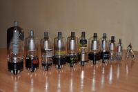
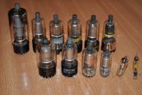
radhoo, Sat Mar 26 2011, 09:56PM
I wonder how happy would be the 2X2 tube to get connected to the 140KV supply that I've put together today:
 . Oil would be needed because the tube's so short
I've got a new lot of rectifiers myself, I'll be testing them soon:


Re: Vacuum Rectifiers X-rays report
Proud Mary, Sat Mar 26 2011, 11:27PM
I have two small wire-ended EHT rectifiers that I thought I would try tomorrow afternoon - they are a Mullard EY51 and a Brimar R16, both 17kV PIV from the days of small black-and-white televisions.
Proud Mary, Sat Mar 26 2011, 11:27PM
I have two small wire-ended EHT rectifiers that I thought I would try tomorrow afternoon - they are a Mullard EY51 and a Brimar R16, both 17kV PIV from the days of small black-and-white televisions.
Re: Vacuum Rectifiers X-rays report
Nah, Sun Mar 27 2011, 02:05AM
Top-noch work, guys!
Nah, Sun Mar 27 2011, 02:05AM
Top-noch work, guys!
Re: Vacuum Rectifiers X-rays report
Proud Mary, Sun Apr 03 2011, 06:16PM
2X2A Air Transmission Graphs for Va = 25kV
Here are the air transmission figures for my contribution to the project - i.e. up to 25keV max photon energy.
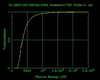
At 5cm in air 295K 760 Torr
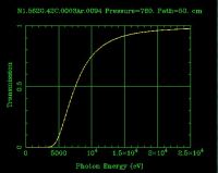
At 50cm in air 295K 760 Torr
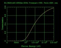
At 500cm in air 295K 760 Torr
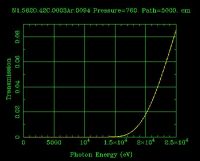
At 5000cm in air 295K 760 Torr
Proud Mary, Sun Apr 03 2011, 06:16PM
2X2A Air Transmission Graphs for Va = 25kV
Here are the air transmission figures for my contribution to the project - i.e. up to 25keV max photon energy.

At 5cm in air 295K 760 Torr

At 50cm in air 295K 760 Torr

At 500cm in air 295K 760 Torr

At 5000cm in air 295K 760 Torr
Re: Vacuum Rectifiers X-rays report
radhoo, Sun Apr 03 2011, 10:07PM
Stella, this seems like very useful info, how where the graphs processed/drawn?
what was the mechanism in taking these values?
it the first line referring to air composition? N , O , Ar ? How was this data gathered?
Thanks!
radhoo, Sun Apr 03 2011, 10:07PM
Stella, this seems like very useful info, how where the graphs processed/drawn?
what was the mechanism in taking these values?
it the first line referring to air composition? N , O , Ar ? How was this data gathered?
Thanks!
Re: Vacuum Rectifiers X-rays report
Proud Mary, Sun Apr 03 2011, 10:56PM
I used the gas transmission calculator on the website of The Center for X-Ray Optics and Advanced Light Sources at Lawrence Berkeley National Laboratory. You'll find the gas transmission calculator in the X-Ray Interactions With Matter section of the X-Ray Database.
While you're there, you can get yourself a free pdf copy of their X-Ray Data Booklet from here:

Proud Mary, Sun Apr 03 2011, 10:56PM
radhoo wrote ...
Stella, this seems like very useful info, how where the graphs processed/drawn?
what was the mechanism in taking these values?
it the first line referring to air composition? N , O , Ar ? How was this data gathered?
Thanks!
Stella, this seems like very useful info, how where the graphs processed/drawn?
what was the mechanism in taking these values?
it the first line referring to air composition? N , O , Ar ? How was this data gathered?
Thanks!
I used the gas transmission calculator on the website of The Center for X-Ray Optics and Advanced Light Sources at Lawrence Berkeley National Laboratory. You'll find the gas transmission calculator in the X-Ray Interactions With Matter section of the X-Ray Database.

While you're there, you can get yourself a free pdf copy of their X-Ray Data Booklet from here:

Re: Vacuum Rectifiers X-rays report
radhoo, Mon Apr 04 2011, 08:32AM
Nice find, for a moment I had the impression that you did the measurements yourself (including the chemical composition of air), and I was like "Wow - how did she do this "? . Nevertheless a valuable piece of information you posted there.
radhoo, Mon Apr 04 2011, 08:32AM
Nice find, for a moment I had the impression that you did the measurements yourself (including the chemical composition of air), and I was like "Wow - how did she do this "? . Nevertheless a valuable piece of information you posted there.
Re: Vacuum Rectifiers X-rays report
Proud Mary, Mon Apr 04 2011, 10:13AM
Golly, Radu, you didn't think I'd want to spend all afternoon punching numbers into a keyboard, when I could be sitting out in the garden with a bottle of wine!
Proud Mary, Mon Apr 04 2011, 10:13AM
radhoo wrote ...
Nice find, for a moment I had the impression that you did the measurements yourself (including the chemical composition of air), and I was like "Wow - how did she do this "? . Nevertheless a valuable piece of information you posted there.
Nice find, for a moment I had the impression that you did the measurements yourself (including the chemical composition of air), and I was like "Wow - how did she do this "? . Nevertheless a valuable piece of information you posted there.
Golly, Radu, you didn't think I'd want to spend all afternoon punching numbers into a keyboard, when I could be sitting out in the garden with a bottle of wine!

Re: Vacuum Rectifiers X-rays report
radhoo, Mon Apr 04 2011, 10:13PM
radhoo, Mon Apr 04 2011, 10:13PM
Proud Mary wrote ...
Golly, Radu, you didn't think I'd want to spend all afternoon punching numbers into a keyboard, when I could be sitting out in the garden with a bottle of wine!
Actually after all that exotic equipment I've seen you have and use, this would have been quite probable :) .Golly, Radu, you didn't think I'd want to spend all afternoon punching numbers into a keyboard, when I could be sitting out in the garden with a bottle of wine!

Re: Vacuum Rectifiers X-rays report
Proud Mary, Mon Apr 04 2011, 11:00PM
Who can say?
Proud Mary, Mon Apr 04 2011, 11:00PM
radhoo wrote ...
Proud Mary wrote ...
Golly, Radu, you didn't think I'd want to spend all afternoon punching numbers into a keyboard, when I could be sitting out in the garden with a bottle of wine!
Actually after all that exotic equipment I've seen you have and use, this would have been quite probable :) .Golly, Radu, you didn't think I'd want to spend all afternoon punching numbers into a keyboard, when I could be sitting out in the garden with a bottle of wine!

Who can say?

Re: Vacuum Rectifiers X-rays report
Steve Conner, Tue Apr 05 2011, 08:56AM
I also agree :)
Steve Conner, Tue Apr 05 2011, 08:56AM
radhoo wrote ...
Proud Mary wrote ...
Golly, Radu, you didn't think I'd want to spend all afternoon punching numbers into a keyboard, when I could be sitting out in the garden with a bottle of wine!
Actually after all that exotic equipment I've seen you have and use, this would have been quite probable :) .Golly, Radu, you didn't think I'd want to spend all afternoon punching numbers into a keyboard, when I could be sitting out in the garden with a bottle of wine!

I also agree :)
Re: Vacuum Rectifiers X-rays report
Proud Mary, Tue Apr 05 2011, 06:21PM
2X2A Efficiency As An X-Ray Producer
Efficiency = KV x Z x 10E-6*
where KV is the voltage in kV, and Z is the Atomic Number of the anode material.
The 'target' of the inverted 2X2A is an iron alloy, but with no means at our disposal to determine the other constituent metals, we'll have to proceed as though it were 100% iron, and I don't think we shall be too far wrong.
Thus at 25kV, and an Fe target of Atomic Number 26,
Efficiency = 25 x 26 x 10E-6 = 6.5E-3
This will be my final contribution to this thread, as I have other pressing concerns - especially the need to paint my nails, and get drunk in the garden.
* A working approximation in widespread use.
Proud Mary, Tue Apr 05 2011, 06:21PM
2X2A Efficiency As An X-Ray Producer
Efficiency = KV x Z x 10E-6*
where KV is the voltage in kV, and Z is the Atomic Number of the anode material.
The 'target' of the inverted 2X2A is an iron alloy, but with no means at our disposal to determine the other constituent metals, we'll have to proceed as though it were 100% iron, and I don't think we shall be too far wrong.
Thus at 25kV, and an Fe target of Atomic Number 26,
Efficiency = 25 x 26 x 10E-6 = 6.5E-3
This will be my final contribution to this thread, as I have other pressing concerns - especially the need to paint my nails, and get drunk in the garden.

* A working approximation in widespread use.
Re: Vacuum Rectifiers X-rays report
Linas, Tue May 17 2011, 04:54PM
I have one question
I was playing with my brand new x ray generator (200V 0,3A for tube HV multiplier SMPS) , and started to get headache.
Tube is constructed to create good quality beam, it was shooting all rays out of my house through window, and i was 6m away with at least 20cm of concrete.
also i was diagonally across the concrete wall, so it could be easy as 1m of concrete, and Geiger does not show any sign of high radiation. also test was made near open window, so low O3 concentration...
SO it's just coincidence or just placebo ?
Re: Vacuum Rectifiers X-rays report
uzzors2k, Tue May 17 2011, 07:13PM
I'm a bit late to the party, but this past weekend I was finally able to do some 2X2A experiments of my own. Several years ago (2007) I purchased some American 2X2A tubes for this exact purpose, but seeing Leslie's page on flash x-rays convinced me to try that instead. One weak Marx generator and no x-ray images later I shelfed the project, until seeing Radu's thread here.
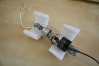
Some quick tests showed that a surprising amount of x-rays were generated, and even with great shielding (~3cm of transformer steel) enough was scattered to register on my Geiger counter at three meters distance. Our bathroom is lined with ceramic tile and on the ground floor, so it seemed an ideal place to run the experiments from here on. Since I still live my parents I needed to make the setup quick to deploy, otherwise I'd never get it setup while they were away. This involved fitting an ammeter, high voltage source, tube mount and shield in the same location. The high voltage source was constructed specifically for this purpose, and consists of two rectified flyback transformers in series driven by a current-mode controller. Voltage can be set from 0-50kV. The transformers are sealed in a PP pipe filled with motor oil. To keep myself safer, I've constructed a fiber optic timer unit and relay, so the exposures can be controlled from a distance. The 2X2A itself is also sealed in oil and wrapped in tin foil to suppress inadvertent lighting of the screen. This also serves to protect the tube itself from arc-overs.
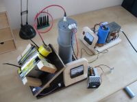
Some tests with the tube showed that unlike the Russian model, the American produces the most x-rays while driven in regular polarity, with the anode at HV. Turning my high voltage supply to max, the voltage across the tube was measured to be 42kV, at 210µA. I took some images of the internal structure to see if any points of localized heating showed up, but nothing stuck out. Due to my camera's built in timer limitations I was only able to run the tube for a few seconds before the picture was taken.
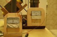
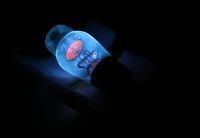
Like Radu discovered however, the American model is far inferior to the Russian in terms of radiation output. I was barely able to x-ray an IC, even with 30s exposure time and digital enhancement. Still, it did work, which is pretty neat considering the basic components used.
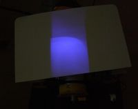
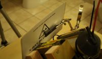
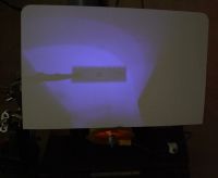
uzzors2k, Tue May 17 2011, 07:13PM
I'm a bit late to the party, but this past weekend I was finally able to do some 2X2A experiments of my own. Several years ago (2007) I purchased some American 2X2A tubes for this exact purpose, but seeing Leslie's page on flash x-rays convinced me to try that instead. One weak Marx generator and no x-ray images later I shelfed the project, until seeing Radu's thread here.

Some quick tests showed that a surprising amount of x-rays were generated, and even with great shielding (~3cm of transformer steel) enough was scattered to register on my Geiger counter at three meters distance. Our bathroom is lined with ceramic tile and on the ground floor, so it seemed an ideal place to run the experiments from here on. Since I still live my parents
 I needed to make the setup quick to deploy, otherwise I'd never get it setup while they were away. This involved fitting an ammeter, high voltage source, tube mount and shield in the same location. The high voltage source was constructed specifically for this purpose, and consists of two rectified flyback transformers in series driven by a current-mode controller. Voltage can be set from 0-50kV. The transformers are sealed in a PP pipe filled with motor oil. To keep myself safer, I've constructed a fiber optic timer unit and relay, so the exposures can be controlled from a distance. The 2X2A itself is also sealed in oil and wrapped in tin foil to suppress inadvertent lighting of the screen. This also serves to protect the tube itself from arc-overs.
Some tests with the tube showed that unlike the Russian model, the American produces the most x-rays while driven in regular polarity, with the anode at HV. Turning my high voltage supply to max, the voltage across the tube was measured to be 42kV, at 210µA. I took some images of the internal structure to see if any points of localized heating showed up, but nothing stuck out. Due to my camera's built in timer limitations I was only able to run the tube for a few seconds before the picture was taken.


Like Radu discovered however, the American model is far inferior to the Russian in terms of radiation output. I was barely able to x-ray an IC, even with 30s exposure time and digital enhancement. Still, it did work, which is pretty neat considering the basic components used.


Re: Vacuum Rectifiers X-rays report
Patrick, Tue May 17 2011, 09:58PM
When used as intended is lower radiation more desirable? You all use these device for an off-label purpose so I have no doubt the Russian one is better for more X-rays, but most makers probably try to avoid excessive radiation?
Putin cant start car....
Patrick, Tue May 17 2011, 09:58PM
Uzzors wrote ...
.... the American model is far inferior to the Russian in terms of radiation output....
Not to put my huevos out, but when you say the American version is inferior to the Russian one, what do you mean?.... the American model is far inferior to the Russian in terms of radiation output....
When used as intended is lower radiation more desirable? You all use these device for an off-label purpose so I have no doubt the Russian one is better for more X-rays, but most makers probably try to avoid excessive radiation?
Putin cant start car....

Re: Vacuum Rectifiers X-rays report
uzzors2k, Wed May 18 2011, 07:55AM
Haha, I had a feeling some patriot would feel his feathers ruffled from line. To clarify, which I can do using just the segment you've quoted: the American model produces less radiation than the Russian model, which in this application is undesirable, and thus inferior. On the contrary, the American model is superior in terms of tube characteristics (I assume), shock tolerance and aesthetics, but that's of no concern to me in this project.
You've labeled me as a commie now haven't you.

Re: Vacuum Rectifiers X-rays report
Patrick, Wed May 18 2011, 02:37PM

Patrick, Wed May 18 2011, 02:37PM
Uzzors wrote ...
Haha, I had a feeling some patriot would feel his feathers ruffled from line. To clarify, which I can do using just the segment you've quoted: the American model produces less radiation than the Russian model, which in this application is undesirable, and thus inferior. On the contrary, the American model is superior in terms of tube characteristics (I assume), shock tolerance and aesthetics, but that's of no concern to me in this project.
I was being Facetiuos with the "huevos"commemt, but thats what I thought your were meaning, about the American version.Haha, I had a feeling some patriot would feel his feathers ruffled from line. To clarify, which I can do using just the segment you've quoted: the American model produces less radiation than the Russian model, which in this application is undesirable, and thus inferior. On the contrary, the American model is superior in terms of tube characteristics (I assume), shock tolerance and aesthetics, but that's of no concern to me in this project.
Uzzors wrote ...
You've labeled me as a commie now haven't you.
Not yet. You've labeled me as a commie now haven't you.


Re: Vacuum Rectifiers X-rays report
radhoo, Tue May 31 2011, 03:48PM
Hi Eirik,
It's great that you're using your DSLR for these photos, it brings some serious enhancement to captured images quality, I only wish you did more of those. Are you planning to try your setup with other vacuum tubes as well?
radhoo, Tue May 31 2011, 03:48PM
Hi Eirik,
It's great that you're using your DSLR for these photos, it brings some serious enhancement to captured images quality, I only wish you did more of those. Are you planning to try your setup with other vacuum tubes as well?
Re: Vacuum Rectifiers X-rays report
Nah, Tue May 31 2011, 07:29PM
I would suggest some of the early diodes in tvs, i'm talking from the 30's.
Nah, Tue May 31 2011, 07:29PM
I would suggest some of the early diodes in tvs, i'm talking from the 30's.
Re: Vacuum Rectifiers X-rays report
radhoo, Thu May 16 2013, 12:16PM
Russian GP-5 vs Russian 2x2
I remember Linas mentioning the GP-5 tube. Indeed it looks like a good candidate for the purpose of this topic, given its size and solid construction:
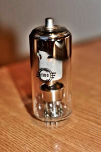
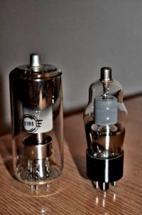
It does produce x-rays when energized at 50KV in reverse polarity, but nothing compared to the 2X2. Here are some images:
GP-5 in normal polarization (+50KV to anode)
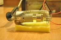

The first two pictures are original, as recorded by the camera.
The third picture was enhanced in software with a Gamma Correction factor of 3 (increased exposure/luminosity)
The forth shows the same setup, but having a Kodak intensifier paper cylinder wrapped around the tube. Software enhancement, with the same gamma factor of 3. No green fluorescence can be observed.
Exposure settings are: 2nd picture: 10s/F5.6/ISO 500 and for the 4th picture: 13s/F5.6/ISO 800
GP-5 in inverse polarization (+50KV to the cathode)
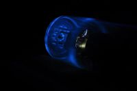
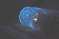
2nd picture is a gamma corrected variant of the first, factor of 3. 1st picture settings: 13s/F5.6/ISO 800
Here is the tube with the Kodak intensifier screen:

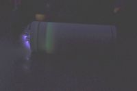
2nd picture is a gamma corrected variant of the first, factor of 3. 1st picture settings: 15s/F5.3/ISO 640
Some green fluorescence is visible.
And here is the 2X2 tube, place instead of the GP-5, in the same exact setup:
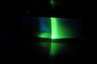
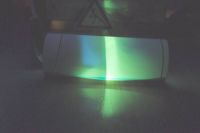
2nd picture is a gamma corrected variant of the first, factor of 3. 1st picture settings: 15s/F5.3/ISO 640
Increased amounts of radiation are being produced.
Conclusion: at 50KV, the GP-5 produces some x-ray emissions, but nothing compared to the 2X2.
2X2 energized at 50KV in reverse polarity
See the impact zones on the heat shield and glass.
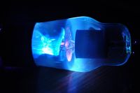
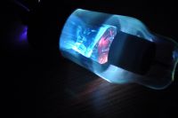
radhoo, Thu May 16 2013, 12:16PM
Russian GP-5 vs Russian 2x2
I remember Linas mentioning the GP-5 tube. Indeed it looks like a good candidate for the purpose of this topic, given its size and solid construction:


It does produce x-rays when energized at 50KV in reverse polarity, but nothing compared to the 2X2. Here are some images:
GP-5 in normal polarization (+50KV to anode)


The first two pictures are original, as recorded by the camera.
The third picture was enhanced in software with a Gamma Correction factor of 3 (increased exposure/luminosity)
The forth shows the same setup, but having a Kodak intensifier paper cylinder wrapped around the tube. Software enhancement, with the same gamma factor of 3. No green fluorescence can be observed.
Exposure settings are: 2nd picture: 10s/F5.6/ISO 500 and for the 4th picture: 13s/F5.6/ISO 800
GP-5 in inverse polarization (+50KV to the cathode)


2nd picture is a gamma corrected variant of the first, factor of 3. 1st picture settings: 13s/F5.6/ISO 800
Here is the tube with the Kodak intensifier screen:


2nd picture is a gamma corrected variant of the first, factor of 3. 1st picture settings: 15s/F5.3/ISO 640
Some green fluorescence is visible.
And here is the 2X2 tube, place instead of the GP-5, in the same exact setup:


2nd picture is a gamma corrected variant of the first, factor of 3. 1st picture settings: 15s/F5.3/ISO 640
Increased amounts of radiation are being produced.
Conclusion: at 50KV, the GP-5 produces some x-ray emissions, but nothing compared to the 2X2.
2X2 energized at 50KV in reverse polarity
See the impact zones on the heat shield and glass.


Re: Vacuum Rectifiers X-rays report
Proud Mary, Thu May 16 2013, 01:07PM
Interesting experiments, Radhu, but the results are no surprise.
Let us think about the basic differences between 2X2 and GP-5.
2X2 was designed as a high voltage rectifier diode during the Second World War. It was designed to rectify RMS max 5.5 kV, and 12.5 kV PIV. This means that when operated within its design range, the soft X-rays produced by electron bombardment would be completely stopped by the glass envelope, so no X-ray shielding was included in the design.
By contrast, the Svetlana GP-5 was designed as an EHT shunt stabiliser triode for colour television service. Its maximum anode working voltage was 30 kV, so effective X-ray shielding has been built into the design, as we see clearly in your pictures. The envelope glass very probably contains lead or other heavy elements to attenuate radiation leaking round the shield. As colour TV broadcasting did not start in the former Soviet Union until 1967, I would judge this valve to have been designed after the significant X-ray hazard of earlier American EHT stabiliser triodes like 6BK4 (1955) was well known. So your experiments have proved the superiority of Soviet engineering! :)
Stella
Re: Vacuum Rectifiers X-rays report
radhoo, Thu May 16 2013, 01:19PM
Thanks for the adding these details. Indeed the GP-5 seems to come with lead glass, as the tubes feel so heavy.
radhoo, Thu May 16 2013, 01:19PM
Thanks for the adding these details. Indeed the GP-5 seems to come with lead glass, as the tubes feel so heavy.
Re: Vacuum Rectifiers X-rays report
Proud Mary, Thu May 16 2013, 08:10PM
I have sometimes wondered - and I am sure you will have thought of this too - how much the application of an external magnetic field might be able to increase the output energy by a partial 'cyclotron effect.' Even if it added only a short extra distance to the electron path, it might increase the output energy considerably.
Success is most likely to come by choosing a high voltage valve with the most favourable electrode architecture, one where at least part of the electron path would not be shielded from the magnetic field by, for example, the anode.
What do you think?
Proud Mary, Thu May 16 2013, 08:10PM
radhoo wrote ...
Thanks for the adding these details. Indeed the GP-5 seems to come with lead glass, as the tubes feel so heavy.
Thanks for the adding these details. Indeed the GP-5 seems to come with lead glass, as the tubes feel so heavy.
I have sometimes wondered - and I am sure you will have thought of this too - how much the application of an external magnetic field might be able to increase the output energy by a partial 'cyclotron effect.' Even if it added only a short extra distance to the electron path, it might increase the output energy considerably.
Success is most likely to come by choosing a high voltage valve with the most favourable electrode architecture, one where at least part of the electron path would not be shielded from the magnetic field by, for example, the anode.
What do you think?
Re: Vacuum Rectifiers X-rays report
radhoo, Thu May 16 2013, 09:00PM
Your idea is interesting and it makes sense, of course there are a few limitations given the different purpose of the valves we find (eg. fragility of the 2X2, improper electrode placement in most tubes, etc), but these are of secondary importance.
Personally I don't know much about magnetic acceleration of the electrons, just the basic theory, but from that to an actual working prototype there is a path of trial and error that is yet unknown to me. I would use an electromagnet, and not a permanent magnet, but I have no clue on what the field parameters should look like, nor the driving signal. Any ideas?
Re: Vacuum Rectifiers X-rays report
Proud Mary, Thu May 16 2013, 10:23PM
Yes, I do! We both know the electrode architecture of the Russian 2X2A very well, and I think it is a very good place to start because
(a) there is a big space between cathode and anode.
(b) the valve will still operate for our purpose with the normal polarity reversed, so the anode bell is now the field emission source.
If you think of the edge of the anode bell - a sharp edge - the field emission from here will be completely exposed to an external magnetic field.
I am thinking of using two large, strong neodymium magnets because they are very compact with intense fields on very small pole surface areas, and come with M8 screw threads already tapped into them for easy mounting on to a frame - an aluminium frame would perhaps be good.
Initial tests could be
(1) change of relative fluence (GM or ion counter etc)
(2) Change of anode current. If the electron path length is curved by the field, it will be longer, so the anode impedance will rise. This effect (if it exists at all! :) ) might be too small to detect with my simple equipment. If it is a few μA out of a standing anode current that wanders around 200 μA it might be possible to detect it by statistical means with enough samples. We shall see!
(3) A radiation pattern test, with the 2X2A inside a Gd2O2S cylinder.
If it works, then we can develop a theory of operation, expressions, to predict how it would change if we changed the magnetic field.
How does that sound?
Proud Mary, Thu May 16 2013, 10:23PM
radhoo wrote ...
Your idea is interesting and it makes sense, of course there are a few limitations given the different purpose of the valves we find (eg. fragility of the 2X2, improper electrode placement in most tubes, etc), but these are of secondary importance.
Personally I don't know much about magnetic acceleration of the electrons, just the basic theory, but from that to an actual working prototype there is a path of trial and error that is yet unknown to me. I would use an electromagnet, and not a permanent magnet, but I have no clue on what the field parameters should look like, nor the driving signal. Any ideas?
Yes, I do! We both know the electrode architecture of the Russian 2X2A very well, and I think it is a very good place to start because
(a) there is a big space between cathode and anode.
(b) the valve will still operate for our purpose with the normal polarity reversed, so the anode bell is now the field emission source.
If you think of the edge of the anode bell - a sharp edge - the field emission from here will be completely exposed to an external magnetic field.
I am thinking of using two large, strong neodymium magnets because they are very compact with intense fields on very small pole surface areas, and come with M8 screw threads already tapped into them for easy mounting on to a frame - an aluminium frame would perhaps be good.
Initial tests could be
(1) change of relative fluence (GM or ion counter etc)
(2) Change of anode current. If the electron path length is curved by the field, it will be longer, so the anode impedance will rise. This effect (if it exists at all! :) ) might be too small to detect with my simple equipment. If it is a few μA out of a standing anode current that wanders around 200 μA it might be possible to detect it by statistical means with enough samples. We shall see!
(3) A radiation pattern test, with the 2X2A inside a Gd2O2S cylinder.
If it works, then we can develop a theory of operation, expressions, to predict how it would change if we changed the magnetic field.
How does that sound?
Re: Vacuum Rectifiers X-rays report
radhoo, Sun Jun 09 2013, 04:18PM
Sounds great.
My only ion chamber is a CDV717 unit:
I'll need something more sensitive to get a clue on what the 2X2 outputs. And a ion chamber seems to be the perfect candidate for getting an idea on the dose for making comparisons between the various setups, even if not calibrated in standard units.
My geiger counters are getting easily saturated even at 1 meter away from the 2x2 (showing >999uSv/h, etc). Can't use them for this purpose. Good that all my related tests, without exception, have been performed remotely, and the camera was the only observer exposed.
radhoo, Sun Jun 09 2013, 04:18PM
Sounds great.
My only ion chamber is a CDV717 unit:

I'll need something more sensitive to get a clue on what the 2X2 outputs. And a ion chamber seems to be the perfect candidate for getting an idea on the dose for making comparisons between the various setups, even if not calibrated in standard units.
My geiger counters are getting easily saturated even at 1 meter away from the 2x2 (showing >999uSv/h, etc). Can't use them for this purpose. Good that all my related tests, without exception, have been performed remotely, and the camera was the only observer exposed.
Print this page


