
yet another DRSSTC - reality check
Dr. Shark, Sun May 28 2006, 05:19PMYeah, this is about the 100th thread about DRSSTCs, but I know a cool toy when I see one for about 100 times, so I resumed work on mine...
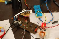
working on a 24V supply, it seems to be OK, but before firing it up at full mains voltage (no, I don't have a variac here), I thought I'd better ask if everything looks OK so far:
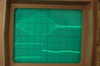
The lower trace is what my halfbride of small, cute TO220 IGBTs sees, and the upper trace is picked up from the air, i.e. what is radiated from the secondary. For me this looks OK, I have tuned it so the secondary voltage rises as high as it goes before the interruptor kicks in. It does not break out at 24V, but when I put a screwdriver near it, it arcs about 1cm, making an awfull sound at about 4kHz from the interruptor

The circuit BTW is Conner Steves dirty weekend DRSSTC, simple enough for me (unlike his new design), but still fully featured with primary feedback and synchronised interruptor.
So, should I dare plug it in?
EDIT: completey forgot to talk about tuning: My secondary with its 5pF topload runs at a frequency of around 350kHz, so I went for a primary with 4.3uH and chopped up my way too big MMC to 40nF. Should that be allright, or would I be better of with more capacitance and less primary turns (5 at the moment)?
Re: yet another DRSSTC - reality check
Steve Ward, Sun May 28 2006, 06:12PM
From the information given, it looks OK. Dont run it at 4khz PRF when you plug it into the wall! Start out low, like 60bps. You shouldnt need more than 180bps to achieve full spark length anyway, and the very high PRF just causes a lot of stress to your components. Good luck!
Re: yet another DRSSTC - reality check
Dr. Shark, Mon May 29 2006, 06:17PM
WOOO-HA! I got it going! It only produces about 3" of streamers right now, but I think that I am on the right track. It just seems feedback is not working, neither with a current transformer nor with an antenna. I have no idea how to fix this, but after it took me a long time to figure out that the MMC and primary should be in series and not parallel (DOH!), I think I might never find the problem
Anyway, this is really funny: I am using a 3300uF smoothing cap on the 300V line, just like the Steves do. However, when I plug the thing out, it keeps firing away for about a minute, since the cap takes so long to drain at my low rep rate...
Dr. Shark, Mon May 29 2006, 06:17PM
WOOO-HA! I got it going! It only produces about 3" of streamers right now, but I think that I am on the right track. It just seems feedback is not working, neither with a current transformer nor with an antenna. I have no idea how to fix this, but after it took me a long time to figure out that the MMC and primary should be in series and not parallel (DOH!), I think I might never find the problem

Anyway, this is really funny: I am using a 3300uF smoothing cap on the 300V line, just like the Steves do. However, when I plug the thing out, it keeps firing away for about a minute, since the cap takes so long to drain at my low rep rate...
Re: yet another DRSSTC - reality check
Dr. Shark, Mon May 29 2006, 06:30PM
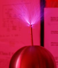
Actually I have massive arcing from the top turns of the secondary, I wonder why that could be?
Dr. Shark, Mon May 29 2006, 06:30PM

Actually I have massive arcing from the top turns of the secondary, I wonder why that could be?
Re: yet another DRSSTC - reality check
Dr. Shark, Mon May 29 2006, 06:38PM
Ah, I actually found the reason for using these huge electrolytics:
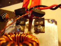
It gives a huge bang when you blow up the IGBTs!
Dr. Shark, Mon May 29 2006, 06:38PM
Ah, I actually found the reason for using these huge electrolytics:

It gives a huge bang when you blow up the IGBTs!
Re: yet another DRSSTC - reality check
Marko, Mon May 29 2006, 06:38PM
What are you using as divider caps?
With PLL it's nice that it oscillates always no matter if it's tuned or not.
I'm using steve ward's crappy circuit and I can't get mine oscillating (doh).
I wonder why is so hard to get current feedback working reliably.
Marko, Mon May 29 2006, 06:38PM
What are you using as divider caps?
With PLL it's nice that it oscillates always no matter if it's tuned or not.
I'm using steve ward's crappy
 circuit and I can't get mine oscillating (doh).
I wonder why is so hard to get current feedback working reliably.
Re: yet another DRSSTC - reality check
Dr. Shark, Mon May 29 2006, 07:10PM
Wow, this time an even louder bang, and I did not even turn up the break rate!
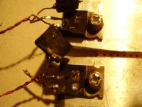
but just as I was bending down to pull the plug (yeah, fuses are for whimps), this happened
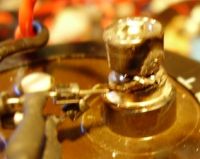
and nearly deafend my left ear. Gotta be more careful around those TCs!
Firkragg, the halfbridge has two 3.3uF 250V caps. I am not sure if it is so nice that the PLL just forces oscillations, since I am pretty sure I am loosing my IGBTs due to non-zero switching, for the lack of feedback. Or maybe those 10A TO220 devices are just not up to the job :)
EDIT: Now I blew up the set of IGBTs for the third time, but I think I figured out why: I did not use Zeners on the gates, because I though they are only for static discharge protection, and not really needed. Wrong! Aparently the transients on the drain get coupled through. But I still need to fix that darn feedback issue. Maybe I blew the 4046 PLL, that has happened to me before...
Dr. Shark, Mon May 29 2006, 07:10PM
Wow, this time an even louder bang, and I did not even turn up the break rate!

but just as I was bending down to pull the plug (yeah, fuses are for whimps), this happened

and nearly deafend my left ear. Gotta be more careful around those TCs!
Firkragg, the halfbridge has two 3.3uF 250V caps. I am not sure if it is so nice that the PLL just forces oscillations, since I am pretty sure I am loosing my IGBTs due to non-zero switching, for the lack of feedback. Or maybe those 10A TO220 devices are just not up to the job :)
EDIT: Now I blew up the set of IGBTs for the third time, but I think I figured out why: I did not use Zeners on the gates, because I though they are only for static discharge protection, and not really needed. Wrong! Aparently the transients on the drain get coupled through. But I still need to fix that darn feedback issue. Maybe I blew the 4046 PLL, that has happened to me before...
Re: yet another DRSSTC - reality check
Marko, Mon May 29 2006, 07:53PM
3,3uF seems way too low for a divider.
You have only 75 milijoules of energy for each half-cycle (before both caps can recharge from big one).
Just for you not to wonder why are your sparks small after (I use two 470uF caps for divider, for example. Sometimes even entire filtering pari is made of two caps and they are fed to halfbridge
(sometimes there is a doubler, etc).
I also have similar problems with feedback (but mine doesn't work at all), I guess we should wait for Steve
PS. antenna feedback should work, try getting it pretty close to coil and see if PLL is responding!
Did you check the circuit for bugs before, does it lock to weak external signal?
Marko, Mon May 29 2006, 07:53PM
3,3uF seems way too low for a divider.
You have only 75 milijoules of energy for each half-cycle (before both caps can recharge from big one).
Just for you not to wonder why are your sparks small after (I use two 470uF caps for divider, for example. Sometimes even entire filtering pari is made of two caps and they are fed to halfbridge
(sometimes there is a doubler, etc).
I also have similar problems with feedback (but mine doesn't work at all), I guess we should wait for Steve

PS. antenna feedback should work, try getting it pretty close to coil and see if PLL is responding!
Did you check the circuit for bugs before, does it lock to weak external signal?
Re: yet another DRSSTC - reality check
Dr. Shark, Mon May 29 2006, 08:03PM
Should 25mJ not be plenty for each half cycle? My MMC is only 50nF now, so I think 3uF to feed it is plenty... besides I don't have any bigger capacitors, and I think you cannot really get much bigger. Electrolytics are probably just way too slow.
Regarding the feedback, with the antenna I get a nice clean squarewave into the PLLs input, it just doesn't seem to care about it. Maybe it is blown...
Well, waiting for one of the Steves sounds like a good plan. In the meantime, a macro of a dead IGBT:
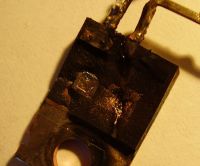

Re: yet another DRSSTC - reality check
Marko, Mon May 29 2006, 08:32PM
''IGBT's Die In Hot Arcs''
With DRSSTC, it's not just all about charging-discharging MMC. Far from that.
You store the energy in primary LC (voltage and current rise to terrible levels) and it is also transferred to secondary very quicky (depending on coupling)
You need few serious joules of bang energy during interrupter cycle, and you don't want these caps to limit it then.
You want the most of energy to be transferred in the shortest time so you can turn the burst off with full spark length.
Let's say it is fine for now, and later you can add some lytics parallel to these caps. (Im also using normal ones paaralel to my divider).
Check the PLL board for bugs, obivously problem lies in there

Re: yet another DRSSTC - reality check
Steve Ward, Mon May 29 2006, 10:26PM
Guys, if you havent tried already, reverse your feedback phasing from the CT. My coils have absolutely no problems with the primary feedback, they never lose feedback, and never have difficulty starting up.
If you are using an antenna, you can reverse the feedback phasing by swapping the connections to your primary coil. This only works if your feedback is based off of the seconary of the TC! If you are using primary feedback, you must either 1) invert the gate drive signal (you can swap your gate drivers around), or 2) swap the output leads from the feedback CT, or 3) pass the conductor through the CT in the opposite direction. Either of these 3 will change the phasing by 180 degrees. One phasing will not work, the other will.
If this doesnt resolve your problems, let me know.
Re: yet another DRSSTC - reality check
Wolfram, Mon May 29 2006, 10:31PM
Are the IGBTs IRG4BC20UDs?
Wolfram, Mon May 29 2006, 10:31PM
Are the IGBTs IRG4BC20UDs?
Re: yet another DRSSTC - reality check
Dr. Shark, Tue May 30 2006, 07:46AM
Yes Anders, indeed they are. And just like you probably did, I got them by the 100s of ebay.de, for just a few cents a piece, so I don't mind blowing them like popcorn.
I think my feedback problem is somewhat more fundamental, maybe a bug in the circuit. I'll worry about that before I follow Firkraggs advice and go for (hopefully) bigger sparks. But really, I think I wont get that much more than the current 4" from the TO220s
Re: yet another DRSSTC - reality check
Marko, Tue May 30 2006, 06:54PM
Joe, what voltage were you using for that streamer from the pic?
Im fighting for mere few centimeters at 30V...
Your antenna definitely should work, try replacing 4049 if it is blown.
Problem is definitely somewhere in the circuit...
Marko, Tue May 30 2006, 06:54PM
Joe, what voltage were you using for that streamer from the pic?
Im fighting for mere few centimeters at 30V...
Your antenna definitely should work, try replacing 4049 if it is blown.
Problem is definitely somewhere in the circuit...
Re: yet another DRSSTC - reality check
HV Enthusiast, Tue May 30 2006, 07:43PM
Uh . . .
Fighting for a few centimeters arc with a bridge voltage of 30V should be expected and is quite normal.
On my DRSSTC II system, I need to have about 70V on the bridge for 1 inch output.
Sounds to me, if you are getting only a few cm at 30V bridge voltage, your coil is working perfectly fine.
Re: yet another DRSSTC - reality check
vasil, Tue May 30 2006, 09:03PM
4 kHz PRF...wow. Thats explain the waste of IGBTs. And what ON time?
vasil, Tue May 30 2006, 09:03PM
4 kHz PRF...wow. Thats explain the waste of IGBTs. And what ON time?
Re: yet another DRSSTC - reality check
teravolt, Wed May 31 2006, 03:29AM
is your circuit zero crossing at the right time
teravolt, Wed May 31 2006, 03:29AM
is your circuit zero crossing at the right time
Re: yet another DRSSTC - reality check
Dr. Shark, Thu Jun 01 2006, 11:29AM
@Vasil, the IGBTs stopped blowing up after I put Zeners across the Gate.
@Teravolt, certainly not, since it is running open-loop.
Still no progress, and I am running out of ideas... While the coil runs perfectly (giving about 1cm streamers at 50V and up to 10cm at 300V), I just cant get the PLL to lock. I have replaced the chip, traced all the connections... and the funny thing is that by turning the phase pot, I can slighly change the frequency, so the VCOin at pin 9 is working, only SIGin on pin 14 is completely ignoring what I feed into it. Which is a nice sqare-wave, as checked with a scope. I am using Steves dirty circuit
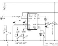
just instead of the capacitor on the very left I have the antenna. The problem is that I haven't got the slightest clue as to how this circuit works, what locking range the PLL should have, and if the values of the resistors and capacitors (other than the timing capacitor) have to be adjusted for my operating frequency of 350kHz, which is probably twice of what Steve was running at.
I am grateful for any ideas!
Dr. Shark, Thu Jun 01 2006, 11:29AM
@Vasil, the IGBTs stopped blowing up after I put Zeners across the Gate.
@Teravolt, certainly not, since it is running open-loop.
Still no progress, and I am running out of ideas... While the coil runs perfectly (giving about 1cm streamers at 50V and up to 10cm at 300V), I just cant get the PLL to lock. I have replaced the chip, traced all the connections... and the funny thing is that by turning the phase pot, I can slighly change the frequency, so the VCOin at pin 9 is working, only SIGin on pin 14 is completely ignoring what I feed into it. Which is a nice sqare-wave, as checked with a scope. I am using Steves dirty circuit

just instead of the capacitor on the very left I have the antenna. The problem is that I haven't got the slightest clue as to how this circuit works, what locking range the PLL should have, and if the values of the resistors and capacitors (other than the timing capacitor) have to be adjusted for my operating frequency of 350kHz, which is probably twice of what Steve was running at.
I am grateful for any ideas!
Re: yet another DRSSTC - reality check
Steve Conner, Thu Jun 01 2006, 11:47AM
If you're using the circuit with an interrupter and small pulse widths (as in a DRSSTC) the PLL doesn't really work so well. You'll never see any behaviour that looks like "snapping into" lock with a sudden increase in output, no matter how hard you tweak it.
The problem is that the PLL always trying to achieve lock, even when the interrupter signal is off and the coil isn't doing anything, hence the phase detector has no input. During these "off" periods, it tends to wander away, and the signal it gets during the "on" periods doesn't last long enough to help it much. So on the whole, it really runs more like a VCO.
Also, due to phase shifts between primary and secondary, when you're using antenna or secondary base current feedback, you won't necessarily get zero-current switching even if it does lock.
These are some of the reasons why I made the Mk2 driver. It has the PLL linked to the interrupter so that it only self-tunes during the burst. Also, the phase shift issue is the reason why I switched to primary current feedback.
Re: yet another DRSSTC - reality check
Dr. Shark, Fri Jun 02 2006, 04:37PM
Whoa, thats harsh! Maybe the project titel "Dirty..." should have put me of, but in my infinite confidence for the brand that is "made in Scotland", I did not for one second doubt that the design was good.
Well, at least this explains why I dont seem to get lock, and I suppose once I change back to primary feedback, it will run well.
So just to make sure, I tweak the frequency for maximum output and then use the phase pot to fine-tune the frequency, or do I need to really adjust the phase?
If I use primary feedback, I will get ZCS no matter how the phase is adjusted, or even if the frequency is off?
Dr. Shark, Fri Jun 02 2006, 04:37PM
Whoa, thats harsh! Maybe the project titel "Dirty..." should have put me of, but in my infinite confidence for the brand that is "made in Scotland", I did not for one second doubt that the design was good.
Well, at least this explains why I dont seem to get lock, and I suppose once I change back to primary feedback, it will run well.

So just to make sure, I tweak the frequency for maximum output and then use the phase pot to fine-tune the frequency, or do I need to really adjust the phase?
If I use primary feedback, I will get ZCS no matter how the phase is adjusted, or even if the frequency is off?
Re: yet another DRSSTC - reality check
Steve Ward, Sat Jun 03 2006, 01:19AM
Nope! You want zero phase shift (or ideally, slightly negative phase shift) with primary feedback, and the PLL will not do that on such short bursts with this circuit. Sorry dude, its basically a VCO with other non-useful features.
Steve Ward, Sat Jun 03 2006, 01:19AM
If I use primary feedback, I will get ZCS no matter how the phase is adjusted, or even if the frequency is off?
Nope! You want zero phase shift (or ideally, slightly negative phase shift) with primary feedback, and the PLL will not do that on such short bursts with this circuit. Sorry dude, its basically a VCO with other non-useful features.
Re: yet another DRSSTC - reality check
Dr. Shark, Sat Jun 03 2006, 07:36AM
Damn! Well, I've got one of Mr Conners new boards, so I guess I will use that for further DRSSTC experiments. This one is probably better suited to SSTC duty, which is no problem, I'll just take out the MMC and I'll be good to go.
Oh, Steve Ward, before I get Steve Conners complicated (like 10 ICs in there) stuff working, I'd like to have a go at your simple micro-DRSSTC. Do you have any schematics, or is it really as simple as you described it in the other thread?
Re: yet another DRSSTC - reality check
EEYORE, Sat Jun 03 2006, 04:49PM
It really is that simple!
I got that little coil working on the 1st go...Promply blew its guts out an hour later when i decided to blast it with full power from the variac...Its got to be one of THE most simple sstc's out(in a good way) ...
...
Matt
EEYORE, Sat Jun 03 2006, 04:49PM
joe wrote ...
Damn! Well, I've got one of Mr Conners new boards, so I guess I will use that for further DRSSTC experiments. This one is probably better suited to SSTC duty, which is no problem, I'll just take out the MMC and I'll be good to go.
Oh, Steve Ward, before I get Steve Conners complicated (like 10 ICs in there) stuff working, I'd like to have a go at your simple micro-DRSSTC. Do you have any schematics, or is it really as simple as you described it in the other thread?
It really is that simple!

I got that little coil working on the 1st go...Promply blew its guts out an hour later when i decided to blast it with full power from the variac...Its got to be one of THE most simple sstc's out(in a good way)
 ...
...Matt
Re: yet another DRSSTC - reality check
Steve Conner, Sat Jun 03 2006, 05:56PM
I'm sure I've said it before, but I'll say it here for the record. If you're looking for a simple DRSSTC controller, it's probably best to use Ward's.
My mk2 driver is a full featured design with all the protection needed for a commercial system. It's debatable whether it's overkill for a hobbyist coil. But I stand by the quality of it, and if you can be bothered building it, I believe it makes a damn fine coil.
I guess what I'm saying is, build Ward's driver unless you love electronics for the sake of it. I don't really have a "My circuit is better than yours" axe to grind any more, so I could care less whose driver you choose.
I'll update my site to give a warning that joe had trouble with the Dirty DRSSTC driver. I don't think anyone else ever tried it on a DRSSTC, and I never really figured out what was going on with it until now when I saw joe's post.
Steve Conner, Sat Jun 03 2006, 05:56PM
I'm sure I've said it before, but I'll say it here for the record. If you're looking for a simple DRSSTC controller, it's probably best to use Ward's.
My mk2 driver is a full featured design with all the protection needed for a commercial system. It's debatable whether it's overkill for a hobbyist coil. But I stand by the quality of it, and if you can be bothered building it, I believe it makes a damn fine coil.
I guess what I'm saying is, build Ward's driver unless you love electronics for the sake of it.
 I don't really have a "My circuit is better than yours" axe to grind any more, so I could care less whose driver you choose.
I'll update my site to give a warning that joe had trouble with the Dirty DRSSTC driver. I don't think anyone else ever tried it on a DRSSTC, and I never really figured out what was going on with it until now when I saw joe's post.
Re: yet another DRSSTC - reality check
Dr. Shark, Sun Jun 04 2006, 10:02AM
Oh come on Steve, I know damn well that your circuits are the finest out there, and since I am a pefectionist I do feel the need to replicate them
Hold on with updating your website though: I did remove the DR part from the coil yesterday and tried driving it as an ISSTC (still interrupted, but much longer on-time, a couple of 100 cycles at least), and still it would not lock. So the problem is more likely to be my implementation than your design. I could still try driving it completely CW, but I doubt that it would make a difference. It still gives nice sparks as an oscillator-based coil, so I'll just leave it as it is. (Well, got to fix those arc-overs to the primary coil, but that's another thing.)
I also noticed a strange problem with my primary feedback transformer: Instead of putting out a square-wave, each time there is a zero-crossing it starts a funny oscillation with about twice the frequency of what the coil is running at. I put it together from two small double-E core transformers, maybe it needs toroids? Once I get that going, I can have some fun with Steve Wards circuit.
Dr. Shark, Sun Jun 04 2006, 10:02AM
Oh come on Steve, I know damn well that your circuits are the finest out there, and since I am a pefectionist I do feel the need to replicate them

Hold on with updating your website though: I did remove the DR part from the coil yesterday and tried driving it as an ISSTC (still interrupted, but much longer on-time, a couple of 100 cycles at least), and still it would not lock. So the problem is more likely to be my implementation than your design. I could still try driving it completely CW, but I doubt that it would make a difference. It still gives nice sparks as an oscillator-based coil, so I'll just leave it as it is. (Well, got to fix those arc-overs to the primary coil, but that's another thing.)
I also noticed a strange problem with my primary feedback transformer: Instead of putting out a square-wave, each time there is a zero-crossing it starts a funny oscillation with about twice the frequency of what the coil is running at. I put it together from two small double-E core transformers, maybe it needs toroids? Once I get that going, I can have some fun with Steve Wards circuit.
Re: yet another DRSSTC - reality check
Steve Ward, Sun Jun 04 2006, 07:16PM
The time needed to lock should depend on the RC filter on the phase comparator output (if i remember the PLL circuit correctly). You can reduce R and C to make it respond faster, but i believe this can cause instability (as with most feedback circuits).
The micro DRSSTC is as simple as i described (hence no schematic). You still have to be careful with the layout, mostly the inductance between gate drivers, GDT and IGBTs. If you chose to use such a circuit (with no synchronous turn off) then you should not run the IGBTs beyond their ratings (i was only running 100A peak with 160Apk rated IGBTs). Also, you will need a tight bridge layout to clamp the *severe* voltage spike that will be present with the hard switching. I really dont recommend it for large coils, as your chances of splattering IGBTs is greatly increased. Its not really that much work to add the flip flop. You could substitute in a D-flip flop as well, provided you have S and R inputs (aka Pre and Clr). If you need any help figuring out the flip flop scheme, just ask.
As to whose circuit is better. Ive always felt that the simpler way is better, just because its easier to understand completely, and when something goes wrong, its not too hard to spot the problem. My circuit starts to fail at high frequencies (despite my micro coil) because there is inherently some delay in the driver and IGBTs, and my circuit does not take care of this at all. So, if your gonna build something under 100khz, there really is not much need for a PLL circuit since you will get pretty darn close to ZCS with decently fast IGBTs. Last i checked, both of our circuits allow for the production of big sparks .
.
Steve Ward, Sun Jun 04 2006, 07:16PM
The time needed to lock should depend on the RC filter on the phase comparator output (if i remember the PLL circuit correctly). You can reduce R and C to make it respond faster, but i believe this can cause instability (as with most feedback circuits).
The micro DRSSTC is as simple as i described (hence no schematic). You still have to be careful with the layout, mostly the inductance between gate drivers, GDT and IGBTs. If you chose to use such a circuit (with no synchronous turn off) then you should not run the IGBTs beyond their ratings (i was only running 100A peak with 160Apk rated IGBTs). Also, you will need a tight bridge layout to clamp the *severe* voltage spike that will be present with the hard switching. I really dont recommend it for large coils, as your chances of splattering IGBTs is greatly increased. Its not really that much work to add the flip flop. You could substitute in a D-flip flop as well, provided you have S and R inputs (aka Pre and Clr). If you need any help figuring out the flip flop scheme, just ask.
As to whose circuit is better. Ive always felt that the simpler way is better, just because its easier to understand completely, and when something goes wrong, its not too hard to spot the problem. My circuit starts to fail at high frequencies (despite my micro coil) because there is inherently some delay in the driver and IGBTs, and my circuit does not take care of this at all. So, if your gonna build something under 100khz, there really is not much need for a PLL circuit since you will get pretty darn close to ZCS with decently fast IGBTs. Last i checked, both of our circuits allow for the production of big sparks
 .
.Re: yet another DRSSTC - reality check
HV Enthusiast, Sun Jun 04 2006, 09:02PM
When comparing circuits, just remember that there is more than one way to skin a cat. . . i also vote that simpler is better (K.I.S.S. principle), but if you think of a better way of doing something, by all means go for it!
Or combine them both into one mutated mess of a circuit!
Remember, even Steve Ward's driver was a combination of several different ideas - flip-flop sychronization from Dan Strother, and the primary feedback scheme from Terry Fritz. Take your idea and keep on mutating. This is the way these things tend to evolve!
HV Enthusiast, Sun Jun 04 2006, 09:02PM
When comparing circuits, just remember that there is more than one way to skin a cat. . . i also vote that simpler is better (K.I.S.S. principle), but if you think of a better way of doing something, by all means go for it!
Or combine them both into one mutated mess of a circuit!

Remember, even Steve Ward's driver was a combination of several different ideas - flip-flop sychronization from Dan Strother, and the primary feedback scheme from Terry Fritz. Take your idea and keep on mutating. This is the way these things tend to evolve!

Re: yet another DRSSTC - reality check
Dr. Shark, Mon Jun 05 2006, 08:46PM
Simpel is better. Here is the minimal DRSSCT driver, true to Steve Wards design:
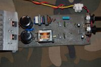
everything, including the interruptor and the half-bridge are on the board, only the MMC will be external. I am kind of scared to test it though, since I have no idea if the GD chips and transformer will be working. Thats really the reason why I liked Steve Conners VCO circuit so much
Oh, the camo background is because I am sooo cool!
Dr. Shark, Mon Jun 05 2006, 08:46PM
Simpel is better. Here is the minimal DRSSCT driver, true to Steve Wards design:

everything, including the interruptor and the half-bridge are on the board, only the MMC will be external. I am kind of scared to test it though, since I have no idea if the GD chips and transformer will be working. Thats really the reason why I liked Steve Conners VCO circuit so much

Oh, the camo background is because I am sooo cool!
Re: yet another DRSSTC - reality check
Marko, Mon Jun 05 2006, 08:59PM
omg omg, the crappiest DRSSTC driver board I've ever seen!
Where is your 74HC14?
Or you are trying to put the signal directly to UCC's?
This will probably work for antenna but I don't know if anyone seriously tried it with current transformers.
Only possibly bad thing I see is the GDT, not clearly visible but do you have windings on both sides of bobbin?
You need tight multifilar winding for very high coupling in GDT.
Marko, Mon Jun 05 2006, 08:59PM
omg omg, the crappiest DRSSTC driver board I've ever seen!

Where is your 74HC14?

Or you are trying to put the signal directly to UCC's?
This will probably work for antenna but I don't know if anyone seriously tried it with current transformers.
Only possibly bad thing I see is the GDT, not clearly visible but do you have windings on both sides of bobbin?
You need tight multifilar winding for very high coupling in GDT.
Re: yet another DRSSTC - reality check
Jim, Tue Jun 06 2006, 11:55PM
Steve just did this...
Jim, Tue Jun 06 2006, 11:55PM
Firkragg wrote ...
Or you are trying to put the signal directly to UCC's?
This will probably work for antenna but I don't know if anyone seriously tried it with current transformers.
Or you are trying to put the signal directly to UCC's?
This will probably work for antenna but I don't know if anyone seriously tried it with current transformers.
Steve just did this...
Re: yet another DRSSTC - reality check
Dr. Shark, Sun Jun 18 2006, 03:42PM
Now I am not sure whether that comment about my TC being "crappy" was meant to be an insult, or just being realistic.
However, instead of firing it up as is I attached an external oscillator to see if everything is working, and figured out that the current feedback is not. I have two 30 turn CTs in series. If I wire them up in parallel ( i.e. as two independent single CTs, they both give a reasonable sqarewave on the output. If I have the two in series, there is no proper output, just some noise. How can this be? Everyone seems to use cascaded CTs, so surely two in series should work better than a single one?
Primary current is probably not very high, since I am driving it far off resonance and at only 30V, getting only 1cm sparks from the coil. Still, the feedback signal should be there, no?
Re: yet another DRSSTC - reality check
Steve Ward, Sun Jun 18 2006, 09:03PM
You are sure you have wired the CTs properly? How are they wired up? I even use a cascaded CT pair for a measurement device with my scope, and it works just great. It does tend to pick up switching noise, but i use that as a benefit so that i can tell where im switching relative to the current .
.
Steve Ward, Sun Jun 18 2006, 09:03PM
You are sure you have wired the CTs properly? How are they wired up? I even use a cascaded CT pair for a measurement device with my scope, and it works just great. It does tend to pick up switching noise, but i use that as a benefit so that i can tell where im switching relative to the current
 .
.Re: yet another DRSSTC - reality check
HV Enthusiast, Sun Jun 18 2006, 10:51PM
You don't need to cascade the current transformers. Instead of winding (2) 30 turn transformers, just wind a 100:1 single one. Using the feedback circuit Steve uses, this is good up to at least 1000A peak current.
HV Enthusiast, Sun Jun 18 2006, 10:51PM
You don't need to cascade the current transformers. Instead of winding (2) 30 turn transformers, just wind a 100:1 single one. Using the feedback circuit Steve uses, this is good up to at least 1000A peak current.
Re: yet another DRSSTC - reality check
Steve Ward, Mon Jun 19 2006, 05:43AM
Yeah, Dan is right. I only cascade them to save myself from winding all those turns on a toroid.
Steve Ward, Mon Jun 19 2006, 05:43AM
Yeah, Dan is right. I only cascade them to save myself from winding all those turns on a toroid.
Re: yet another DRSSTC - reality check
Dr. Shark, Mon Jun 19 2006, 12:07PM
Dr. Shark, Mon Jun 19 2006, 12:07PM
Steve Ward wrote ...
You are sure you have wired the CTs properly? How are they wired up? I even use a cascaded CT pair for a measurement device with my scope, and it works just great. It does tend to pick up switching noise, but i use that as a benefit so that i can tell where im switching relative to the current .
.
Is there any way to wire them improperly? I am now running the coil with just one 30T transformer, because that's what seems to be working for me. It is probably not good to do this, way too much current through the zeners. It works well if I run the coil off 24V, when it gives about 1" of sparks. If I apply full mains voltage, it stops oscillating, but I don't blow any components. Weird...You are sure you have wired the CTs properly? How are they wired up? I even use a cascaded CT pair for a measurement device with my scope, and it works just great. It does tend to pick up switching noise, but i use that as a benefit so that i can tell where im switching relative to the current
 .
. Print this page