
Magnetic field array
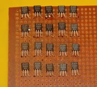
Tesladownunder, Sun May 28 2006, 05:29AMFor an afternoons entertainment I made this. It contains 20 UGN3503 Hall effect devices. They output 2.5 V in no field. Present a south pole and voltage goes up by by 1.3mV/gauss and the same in the reverse. (10,000 gauss = 1 Tesla).
So what did I put on the other side? I would be interested to see what other people would do.
I got 50 of these from eBay and have yet to put the rest in but the concept works. Pics after I get a few replies.
Peter
Re: Magnetic field array
Bjørn, Sun May 28 2006, 06:17AM
20 LEDs on the reverse would do nicely. Since they are quite fast putting them in a row on a spinning disk would be good.
Bjørn, Sun May 28 2006, 06:17AM
20 LEDs on the reverse would do nicely. Since they are quite fast putting them in a row on a spinning disk would be good.
Re: Magnetic field array
Tesladownunder, Sun May 28 2006, 06:31AM
Close but I wanted to indicate field intensity and direction. Spinning disk is a good idea and I have considered this as well. It has the big advantage of giving an analogue smoothness and with a sufficient number of lines should read out with good resolution but with the disadvantage of the mechanics.
Any other suggestions?
Peter
Re: Magnetic field array
Bjørn, Sun May 28 2006, 06:45AM
20 more LEDs of a different colour in antiparallel should give the polarity. Something that could show different frequencies would be a good addition.
Bjørn, Sun May 28 2006, 06:45AM
20 more LEDs of a different colour in antiparallel should give the polarity. Something that could show different frequencies would be a good addition.
Re: Magnetic field array
Tesladownunder, Sun May 28 2006, 06:55AM
That is what I hoped to do but it appears to be a voltage source only not sink. Only really space for 2 standard LED's behind each sensor so it can't be too complicated. (IQ<< 135 in my clan).
One more go.
Peter
Tesladownunder, Sun May 28 2006, 06:55AM
That is what I hoped to do but it appears to be a voltage source only not sink. Only really space for 2 standard LED's behind each sensor so it can't be too complicated. (IQ<< 135 in my clan).
One more go.
Peter
Re: Magnetic field array
joshua_, Sun May 28 2006, 07:50AM
Hmmmm... I'm interested to see what happens with this one. My initial hunch is varying forward voltages on the LEDs meaning that <2.5v is one color, and somehow >2.5 would mean that the ohter color would light up instead... Perhaps in parallel sitting behind a resistor? It's a little late for my brain right now, but whatever it is, I wanna see...
Re: Magnetic field array
Carbon_Rod, Sun May 28 2006, 08:17AM
Comparators are simple. But IIRC the classic LM2914 is a 10 pixel linear bar graph (they sell cheap pre-made car audio level display meters with the LEDs already wired and mounted.)
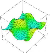
Personally I would prefer to scan the states with an AD unit and use a built-in graphics lib to give a keen display as a crude 2d plot or a slowly revolving 3d plot -- Clean , simple, and adaptable.
Cheers,

Re: Magnetic field array
Tesladownunder, Sun May 28 2006, 08:24AM
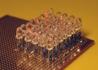
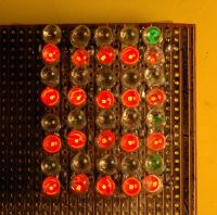
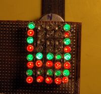
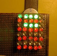
My brain was hurting too but I had available 50 red and 50 green LED's with dropping resistors. The simplest I could get to indicate the three states was to do as you suggested, that is to use the different voltage drops of the two colours. This is not an ideal display but gives the following. Not much room to do much else as you see.
North pole: no lights
no Field: red
South pole: red and green


Re: Magnetic field array
Bored Chemist, Sun May 28 2006, 09:16AM
Thta's quite a nice "work-around" as well as a nice toy. Do you actually have any practical use for it?
Bored Chemist, Sun May 28 2006, 09:16AM
Thta's quite a nice "work-around" as well as a nice toy. Do you actually have any practical use for it?
Re: Magnetic field array
Tesladownunder, Sun May 28 2006, 10:30AM
Actually I had vague plans for looking at the can crusher fields. The UGN3503 is rated as linear to 23kHz and the can crusher runs at a resonant frequency of about 16kHz. Have to be careful not to fry the array or pull it apart as the LED leads are magnetic.
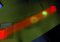
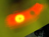
Here are two pics with the array moving by hand in a time exposure shot of 3 secs with magnets below the plastic sheet. Hand is faster than the eye here.
The first one is of a single pass with the south poles of a ferrite ring and a stronger NIB magnet adjacent. The second pic shows the "hole" where the NIB has been turned north up. You can see my foot stationary here for 3 seconds which gives you a clue as to my dancing style.
Peter


Re: Magnetic field array
Simon, Mon May 29 2006, 01:32AM
Jaycar sells bi-colour LEDs. IIRC, (and I'm pretty sure, although I've never used them) their colour depends on the polarity.
In any case, I'm sure there's a simple way to make
no field -> no LEDs
N field -> red LEDs
S field -> green LEDs.
Still a cool toy.
Simon, Mon May 29 2006, 01:32AM
Jaycar sells bi-colour LEDs. IIRC, (and I'm pretty sure, although I've never used them) their colour depends on the polarity.
In any case, I'm sure there's a simple way to make
no field -> no LEDs
N field -> red LEDs
S field -> green LEDs.
Still a cool toy.
Re: Magnetic field array
Tesladownunder, Mon May 29 2006, 03:11AM
I also have tricolour LED's but although this will mean only one LED to fill the space, you still need the dropping resistors (I think). They are also more expensive.
What is probably more useful to me now is a separate indicator after a certain threshold is reached such as 0.1 Tesla. I can still access all the outputs separately so am open to suggestions.
Peter
Re: Magnetic field array
Carbon_Rod, Mon May 29 2006, 06:03AM
Well, I tend to find the Hall-effect sensors are rather slow for some things (convenient and cheap internal preamps.)
Perhaps a stack of old multi-platter hard drive read heads with the super sensitive resistive driver-chip pickups (no its not an error – its an old technique that’s several times more sensitive than just plain passive coils etc.)
Mind you I would be curious to know how fast those cheap magnetic colour changing plastic sheets would respond to flux changes (or expose an impression like film.) The only electromagnet around this place is a little 3Kwatt job that gets too hot and would likely burn anything with plastic =(.
Good luck,
Re: Magnetic field array
Tesladownunder, Mon May 29 2006, 04:57PM
Actually it is the green LED's that are slow compared with the Hall device. Here is a comment from Terry Fritz about LED persistence with the phosphor not decaying for 66ms for the white LEDs and 0.5us for the red LED's (ie 100,000 times faster). Compare that with 50us (23kHz) for the Hall device.
I am not after great sensitivity and really am only interested in fields over 0.1 Tesla so not really looking for ultrasensitive giant magnetoresistive heads.
Peter
Re: Magnetic field array
Carbon_Rod, Tue May 30 2006, 03:05AM
I don’t know what kind of resources are available too you,
If you get those little devices cheap enough perhaps have dedicated North sensors (super bright Red LEDs), and flip another sensor over right beside it for South sensors (super bright Blue Leds). However, both off when neutral is not much of a bonus with twice the sensor cost.
Or have a single resister from the output fed into two LEDs and have two switched power rails for the LEDs (1 NPN 1 PNP and a 555 clocking a few KHz.) As the potential across the LED increases it will turn on one and turn off the other reversed biased LED.
Or a cheap virtual ground made out of an opamp like an LM380, one drive resister, and two LEDs back to back. A few volts above virtual ground will turn on one, and below turns on the other. Only drawback is only low output LEDs could be used (high output units may not work with only +- ~2.5V.)
Edit: Maybe the same divider trick with two resisters (200ohm each should not be too wasteful for a low number of pixels) in series across the rails, two back to front Diodes connected to the node and the sensor output.
Still very neat,
Cheers,
Re: Magnetic field array
Bored Chemist, Tue May 30 2006, 08:11AM
I couldn't get that link to work. Anyway, why would there be a phosphor in green leds? Green leds have been arond much longer than blue ones and to drive a green emiting phosphor would need a blue (or UV) led.
Bored Chemist, Tue May 30 2006, 08:11AM
I couldn't get that link to work. Anyway, why would there be a phosphor in green leds? Green leds have been arond much longer than blue ones and to drive a green emiting phosphor would need a blue (or UV) led.
Re: Magnetic field array
Bjørn, Tue May 30 2006, 09:13AM
Green LEDs using phosphor are very rare, I have never seen one.
I would have used a microcontroller to read the values and to drive the LEDs. It is more relaxing to fiddle with code on a large screen than to fiddle with a soldering iron were there is no room.
Bjørn, Tue May 30 2006, 09:13AM
Green LEDs using phosphor are very rare, I have never seen one.
I would have used a microcontroller to read the values and to drive the LEDs. It is more relaxing to fiddle with code on a large screen than to fiddle with a soldering iron were there is no room.
Re: Magnetic field array
Tesladownunder, Tue May 30 2006, 05:56PM
Agreed. Interestingly I was dividing up the red and green LEDs on the chip appearance. The red LED has a small black chip and I thought the green one looked like a white phosphor LED with the light yellow phosphor. I wasn't really thinking about it at the time.
Fiddling with code is not easy for me so I guess I am stuck with the iron. This might be taking some nasty pulsed fields so best not too close to a computer. The visualisation of an invisible field in realtime is always fascinating with the output next to the input.
Still, an interesting toy at present. I may be able to adjust thresholds by running it with a different supply rail voltage as it will tolerate 4.5 - 6.0 V. I will try to extend this to complete the project, then off to the next one.
Peter
Tesladownunder, Tue May 30 2006, 05:56PM
Bjørn Bæverfjord wrote ...
Green LEDs using phosphor are very rare...I would have used a microcontroller to read the values and to drive the LEDs. It is more relaxing to fiddle with code on a large screen than to fiddle with a soldering iron were there is no room.
Green LEDs using phosphor are very rare...I would have used a microcontroller to read the values and to drive the LEDs. It is more relaxing to fiddle with code on a large screen than to fiddle with a soldering iron were there is no room.
Agreed. Interestingly I was dividing up the red and green LEDs on the chip appearance. The red LED has a small black chip and I thought the green one looked like a white phosphor LED with the light yellow phosphor. I wasn't really thinking about it at the time.
Fiddling with code is not easy for me so I guess I am stuck with the iron. This might be taking some nasty pulsed fields so best not too close to a computer. The visualisation of an invisible field in realtime is always fascinating with the output next to the input.
Carbon_Rod wrote ...
Edit: Maybe the same divider trick with two resisters (200ohm each should not be too wasteful for a low number of pixels) in series across the rails, two back to front Diodes connected to the node and the sensor output.
I thought about a divider but it still added to the parts count. The Hall devices are about AUD$1 each.Edit: Maybe the same divider trick with two resisters (200ohm each should not be too wasteful for a low number of pixels) in series across the rails, two back to front Diodes connected to the node and the sensor output.
Still, an interesting toy at present. I may be able to adjust thresholds by running it with a different supply rail voltage as it will tolerate 4.5 - 6.0 V. I will try to extend this to complete the project, then off to the next one.
Peter
Re: Magnetic field array
Conundrum, Thu Jun 01 2006, 07:57PM
I have a load of similar SMD sensors from old broken video recorders which may well work. Also they output bipolar signals on two pins so it might be possible to connect them directly to bicolour LED's with suitable AC biasing of one pin..
regards, -A
"Bother" said Pooh, as his phone cut off 2 seconds into a call...
Re: Magnetic field array
Tesladownunder, Fri Jun 02 2006, 04:44PM
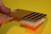
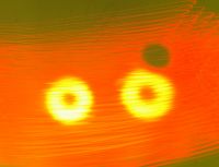
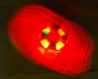
The array now has 44 sensors and gives more detail.
First pic shows side on view.
Second shows mapping of 2 ring magnets with south pole up and one NIB with northpole up. And why are the hot spots yellow and not green? Because it is overlapped by red and the two colours make yellow. (add some blue and they would be white just like in an TV screen)
Third shows a more complex magnet (multisectored magnet out of a video motor) Note that the fields do not line up properly as the red and green LED's are physically separated by 5mm or so.
Peter


Print this page