HV Resistive Divider for NST measurement...
Patrick, Mon Dec 06 2010, 06:12AMWOOOOO HOOOOOO !!!!!!!
ive got a voltage divider that finnally works! , its been 2.5 years of work, and i still have a few more months of work, but for the first time ive got good data that is credible/repeatable.
ok here we go:
remember that the divider is 1000:1
using the Fluke 73 III (ground to 'B') = 6.80V @ 123.2 V input to NST
using the Fluke 79 II (ground to 'A') = 6.68V @ 123.2 Vin
using the Fluke 79 II (ground to 'B') = 6.76V @ 123.2 Vin.
The 79 II says: +/- (0.4% + 1 count), the 79 II, is more accurate, then the 73 III.
The resistor has a max inductance of 5.3uH which is a calculated guess.
now for the ugly part:
the accuracy of the 79 II, and the 200M ohm resistor....
--well the rox series resistor used in this test is spec'ed at +/-1% for 200M Ohms. (upper resistor)so it could be as low as 198M or as high as 202Mohms.
--The 79 II specs are +/- (0.4% + 1 count), the 79 II for the lower resistor 204.8k Ohms.
--For voltage the 79 II is spec'ed as +/-(1.0% + 2 counts) for the range used on 6 to 8 volts.
(There is much more math to add here but its 1am and i need sleep...ZZzzzZzzZzzZZz...)

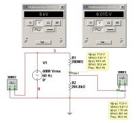
Seen in the schematic, R1 is 198M to 202M ohms, R2 is 205.6k to 204.0k Ohms, so the 13.4kV number could be ( more to add, after sleep )
so, 6.68kV + 6.76kV = 13.4kV with proper sig figs !
from a 12kV NST i think this is credible, as soon as one were to draw arcs it would drop to near or about 12kV im sure. these seem to be credible and repeatable on different days with different set ups. only the occasional flickers of the hundredths place, one or two counts up or down every 3 to 5 seconds.
the math actually works out to 13.44kV but only three digits are justified.

the setup 200M in series with 204.8 kohms. (ignore the digits on the display)

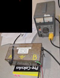
The HV production devices, the variac was used for safety, wall current/voltage is used for all quoted numbers in this post.
(ignore the black square, thats censored info, the dean of engineering and FSB, NKVD, Kgb, CIA cant know what im upto.)

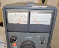
Variac, 55 years old if i can count.
Re: HV Resistive Divider for NST measurement...
Proud Mary, Mon Dec 06 2010, 09:53AM
The construction and testing of the famous Park HV standard resistor still has much in it of interest and relevance even after half a century has gone by since it was invented:

Proud Mary, Mon Dec 06 2010, 09:53AM
The construction and testing of the famous Park HV standard resistor still has much in it of interest and relevance even after half a century has gone by since it was invented:

Re: HV Resistive Divider for NST measurement...
Patrick, Mon Dec 06 2010, 10:08AM
i will read this in detail...
Patrick, Mon Dec 06 2010, 10:08AM
i will read this in detail...
Re: HV Resistive Divider for NST measurement...
Patrick, Wed Dec 08 2010, 04:01AM
Excellent PDF document. TY Proud Mary
Patrick, Wed Dec 08 2010, 04:01AM
Excellent PDF document. TY Proud Mary
Re: HV Resistive Divider for NST measurement...
Proud Mary, Wed Dec 08 2010, 07:21AM
My own HV metrology project has turned out not to be so simple as it first appeared, which is why it has stalled.
A problem has occurred at the lower end of the scale - 10kV, where there is not enough juice going through the 3G to reliably work
the meter without a DC amplifier - which then starts amplifying all sorts of induced signals from the environment, so
far as I can see with my simple equipment. I think I will have to copy the resistor shielding technique used in the Park Resistor, and see how
far that takes me.
Stella
Proud Mary, Wed Dec 08 2010, 07:21AM
Patrick wrote ...
Excellent PDF document. TY Proud Mary
Excellent PDF document. TY Proud Mary
My own HV metrology project has turned out not to be so simple as it first appeared, which is why it has stalled.
A problem has occurred at the lower end of the scale - 10kV, where there is not enough juice going through the 3G to reliably work
the meter without a DC amplifier - which then starts amplifying all sorts of induced signals from the environment, so
far as I can see with my simple equipment. I think I will have to copy the resistor shielding technique used in the Park Resistor, and see how
far that takes me.
Stella
Re: HV Resistive Divider for NST measurement...
Patrick, Wed Dec 08 2010, 02:52PM
i suspected that your 3Gohms was a wee bit on the high side, i too have a 2Gohm resistor and its too weak to be useful.
Patrick, Wed Dec 08 2010, 02:52PM
i suspected that your 3Gohms was a wee bit on the high side, i too have a 2Gohm resistor and its too weak to be useful.
Re: HV Resistive Divider for NST measurement...
Proud Mary, Wed Dec 08 2010, 05:25PM
Still, it is very helpful to know what does not work - especially if we understand why it doesn't - so we can learn by our mistakes, eh, Patrick?
Proud Mary, Wed Dec 08 2010, 05:25PM
Patrick wrote ...
i suspected that your 3Gohms was a wee bit on the high side, i too have a 2Gohm resistor and its too weak to be useful.
i suspected that your 3Gohms was a wee bit on the high side, i too have a 2Gohm resistor and its too weak to be useful.
Still, it is very helpful to know what does not work - especially if we understand why it doesn't - so we can learn by our mistakes, eh, Patrick?

Re: HV Resistive Divider for NST measurement...
Patrick, Wed Dec 08 2010, 05:32PM
Patrick, Wed Dec 08 2010, 05:32PM
Proud Mary wrote ...
Still, it is very helpful to know what does not work - especially if we understand why it doesn't - so we can learn by our mistakes, eh, Patrick?
YES-YES-YES, failures are important lessons learned, just because you learned what doesnt work doesnt mean that realization has no value--quite the opposite.Still, it is very helpful to know what does not work - especially if we understand why it doesn't - so we can learn by our mistakes, eh, Patrick?

Re: HV Resistive Divider for NST measurement...
Patrick, Wed Dec 15 2010, 07:23AM
Update, i have new resistors, now i can make currrent/voltage measurements, at the same time!
using the Fluke 79 II (ground to 'A') = 6.490 kV @ 122.8 Vin. (5.730 Mohms) x (1.133 mA)
using the Fluke 79 II (ground to 'B') = 6.572 kV @ 122.8 Vin. (5.730 Mohms) x (1.147 mA)
total "A across B " Voltage = 6.490 + 6.572 = 13.06 kV
this from what the label says is a 6-0-6 -- 12kV NST,
when i used a 2Gohm resistor/divider i got bogus measurements from 22kV all the way upto 34kV !!!
the 13.06 kV number probably sags a little towards 12kV, as i only had <1.2mA across each secondary. The label says 24mA max out. so i believe the 13kV is accurrate and precise.
Re: HV Resistive Divider for NST measurement...
Patrick, Thu Dec 16 2010, 07:50AM
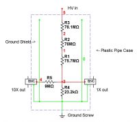
UPDATE: New design.
I will update this design again for 200Hz to 10+ Mhz, in the coming days.
60kV @ DC-200 Hz.

Patrick, Thu Dec 16 2010, 07:50AM
UPDATE: New design.
I will update this design again for 200Hz to 10+ Mhz, in the coming days.
60kV @ DC-200 Hz.

Re: HV Resistive Divider for NST measurement...
Pinky's Brain, Thu Dec 16 2010, 11:45AM
Just curious, how do you know the frequency range? Wrapped your existing one in foil? Or did you calculate approximate stray capacitance to the shield for each resistor and simulated it?
Pinky's Brain, Thu Dec 16 2010, 11:45AM
Just curious, how do you know the frequency range? Wrapped your existing one in foil? Or did you calculate approximate stray capacitance to the shield for each resistor and simulated it?
Re: HV Resistive Divider for NST measurement...
Patrick, Fri Dec 17 2010, 01:05AM
I measure the real capacitence via copper foil, in the PVC as it will be in the final design. i will post pics here shortly.
Patrick, Fri Dec 17 2010, 01:05AM
I measure the real capacitence via copper foil, in the PVC as it will be in the final design. i will post pics here shortly.
Print this page