Disposable camera transformer driver.
Michalis.Biochem, Sat Dec 04 2010, 08:25PMI heard that a disposable camera transformer can be driven using the components found inside a disposable camera(i know, this is what the camera flash board circuit is doing).
but i don't know which components are crucial for this. Dr.2N3055 made a mini tesla coil using this driver, but i can't find anymore info about it.
So here is the thread about the tesla coil that was made using disposable camera parts.
So how can the driver be made?
Re: Disposable camera transformer driver.
Myke, Sat Dec 04 2010, 09:28PM
All you really need is the resistor and transistor to drive the transformer (for the simpler boards). If it's not a simple board, it would be best to keep all the circuitry on the board and remove anything that doesn't drive the transformer. Those things would be the large capacitor, trigger coil, trigger contacts, xenon tube, small capacitor to dump energy into the trigger transformer, etc.
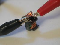
This is a picture of the simple driver taken off the board running from 1.5V (neon light and its current limiting resistor aren't needed for operation):

Re: Disposable camera transformer driver.
ubuntupokemoninc, Sat Dec 04 2010, 09:55PM
i don't see the schematic for the driver to get the 660 volts, what is it?
ubuntupokemoninc, Sat Dec 04 2010, 09:55PM
i don't see the schematic for the driver to get the 660 volts, what is it?
Re: Disposable camera transformer driver.
Michalis.Biochem, Sat Dec 04 2010, 09:57PM
I see, and by saying simple boards you mean the boards that have only one diode, some resistors, a transformer, 2 caps and a transistor?
because that's the simplest board in terms of components i have in my possession.
Couldn't find a schematic either.
Michalis.Biochem, Sat Dec 04 2010, 09:57PM
I see, and by saying simple boards you mean the boards that have only one diode, some resistors, a transformer, 2 caps and a transistor?
because that's the simplest board in terms of components i have in my possession.
ubuntupokemoninc wrote ...
i don't see the schematic for the driver to get the 660 volts, what is it?
i don't see the schematic for the driver to get the 660 volts, what is it?
Couldn't find a schematic either.
Re: Disposable camera transformer driver.
Myke, Sat Dec 04 2010, 11:42PM
Yes, that's the simple board I'm talking about.
He uses two drivers in series fed into a 6 stage CW multiplier as far as I can tell. You don't really need the schematics for this since you can look up each block function individually.
Myke, Sat Dec 04 2010, 11:42PM
Michalis.Biochem wrote ...
I see, and by saying simple boards you mean the boards that have only one diode, some resistors, a transformer, 2 caps and a transistor?
because that's the simplest board in terms of components i have in my possession.
I see, and by saying simple boards you mean the boards that have only one diode, some resistors, a transformer, 2 caps and a transistor?
because that's the simplest board in terms of components i have in my possession.
Yes, that's the simple board I'm talking about.
wrote ...
Couldn't find a schematic either.
ubuntupokemoninc wrote ...
i don't see the schematic for the driver to get the 660 volts, what is it?
i don't see the schematic for the driver to get the 660 volts, what is it?
Couldn't find a schematic either.
He uses two drivers in series fed into a 6 stage CW multiplier as far as I can tell. You don't really need the schematics for this since you can look up each block function individually.
Re: Disposable camera transformer driver.
Michalis.Biochem, Sun Dec 05 2010, 08:15AM
So what i am going to do, is to simply desolder the xformer, the transistor and one of the resistors.
I forgot to mention that the xformer on this board is not of the same type as the one in the picture shown above.
Is this going to work using this xformer?
Michalis.Biochem, Sun Dec 05 2010, 08:15AM
Myke wrote ...
Yes, that's the simple board I'm talking about.
He uses two drivers in series fed into a 6 stage CW multiplier as far as I can tell. You don't really need the schematics for this since you can look up each block function individually.
Michalis.Biochem wrote ...
I see, and by saying simple boards you mean the boards that have only one diode, some resistors, a transformer, 2 caps and a transistor?
because that's the simplest board in terms of components i have in my possession.
I see, and by saying simple boards you mean the boards that have only one diode, some resistors, a transformer, 2 caps and a transistor?
because that's the simplest board in terms of components i have in my possession.
Yes, that's the simple board I'm talking about.
wrote ...
Couldn't find a schematic either.
ubuntupokemoninc wrote ...
i don't see the schematic for the driver to get the 660 volts, what is it?
i don't see the schematic for the driver to get the 660 volts, what is it?
Couldn't find a schematic either.
He uses two drivers in series fed into a 6 stage CW multiplier as far as I can tell. You don't really need the schematics for this since you can look up each block function individually.
So what i am going to do, is to simply desolder the xformer, the transistor and one of the resistors.
I forgot to mention that the xformer on this board is not of the same type as the one in the picture shown above.
Is this going to work using this xformer?
Re: Disposable camera transformer driver.
Myke, Sun Dec 05 2010, 08:37AM
It would be helpful to see a picture of the transformer and board before you remove stuff. I only removed the inverter from the board because it would be smaller. I think the best idea would be to leave the power supply part on the board.
Myke, Sun Dec 05 2010, 08:37AM
It would be helpful to see a picture of the transformer and board before you remove stuff. I only removed the inverter from the board because it would be smaller. I think the best idea would be to leave the power supply part on the board.
Re: Disposable camera transformer driver.
Michalis.Biochem, Sun Dec 05 2010, 08:43AM
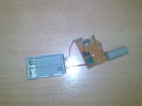
Here is the board

Michalis.Biochem, Sun Dec 05 2010, 08:43AM
Myke wrote ...
It would be helpful to see a picture of the transformer and board before you remove stuff. I only removed the inverter from the board because it would be smaller. I think the best idea would be to leave the power supply part on the board.
It would be helpful to see a picture of the transformer and board before you remove stuff. I only removed the inverter from the board because it would be smaller. I think the best idea would be to leave the power supply part on the board.
Here is the board

Re: Disposable camera transformer driver.
Michalis.Biochem, Mon Dec 06 2010, 10:22AM
Ok, i think i managed to reverse engineer the camera flash board. It comes out that the xformer has 5 pins and is connected with one transistor and one of the resistors. I followed the connections and found out that 2 of the transistor pins were connected with 2 of the xformer pins and the 3rd one was free, and the resistor had both of it pins connected with other 2 pins of the xformer. As a result the xformer has one of its 5 pins free and the transistor one of its 3 pins free. Did i do the whole process well? And if i did it correct which pins are the input or the output?
Re: Disposable camera transformer driver.
Myke, Mon Dec 06 2010, 10:41PM
Ah. Yeah. It should be the simple driver then.
See which pin of the transformer is connected to the diode. This should be your output. The input should be the pin that is connected to the switch that charges the flash on the camera. The entire thing has a common ground meaning the ground for the input is the same as the ground for the output.
Just to make sure, it would probably be the best to leave the transformer, resistor, and transistor on the board and remove everything else. (less work reassembling the driver and you don't have to worry about the phasing of the feed back coil)
Re: Disposable camera transformer driver.
Michalis.Biochem, Tue Dec 07 2010, 08:29PM
By the time you posted, i had already desoldered the components of the whole circuit.
I managed to find the out, but i can't find the input on the board. Would that be the free pin of the transitor?
And which pin would be the ground?
Michalis.Biochem, Tue Dec 07 2010, 08:29PM
Myke wrote ...
The input should be the pin that is connected to the switch that charges the flash on the camera. The entire thing has a common ground meaning the ground for the input is the same as the ground for the output.
The input should be the pin that is connected to the switch that charges the flash on the camera. The entire thing has a common ground meaning the ground for the input is the same as the ground for the output.
By the time you posted, i had already desoldered the components of the whole circuit.
I managed to find the out, but i can't find the input on the board. Would that be the free pin of the transitor?
And which pin would be the ground?
Print this page