If you need assistance, please send an email to forum at 4hv dot org. To ensure your email is not marked as spam, please include the phrase "4hv help" in the subject line. You can also find assistance via IRC, at irc.shadowworld.net, room #hvcomm.
Support 4hv.org!
Donate:
4hv.org is hosted on a dedicated server. Unfortunately, this server costs and we rely on the help of site members to keep 4hv.org running. Please consider donating. We will place your name on the thanks list and you'll be helping to keep 4hv.org alive and free for everyone. Members whose names appear in red bold have donated recently. Green bold denotes those who have recently donated to keep the server carbon neutral.
Special Thanks To:
Aaron Holmes
Aaron Wheeler
Adam Horden
Alan Scrimgeour
Andre
Andrew Haynes
Anonymous000
asabase
Austin Weil
barney
Barry
Bert Hickman
Bill Kukowski
Blitzorn
Brandon Paradelas
Bruce Bowling
BubeeMike
Byong Park
Cesiumsponge
Chris F.
Chris Hooper
Corey Worthington
Derek Woodroffe
Dalus
Dan Strother
Daniel Davis
Daniel Uhrenholt
datasheetarchive
Dave Billington
Dave Marshall
David F.
Dennis Rogers
drelectrix
Dr. John Gudenas
Dr. Spark
E.TexasTesla
eastvoltresearch
Eirik Taylor
Erik Dyakov
Erlend^SE
Finn Hammer
Firebug24k
GalliumMan
Gary Peterson
George Slade
GhostNull
Gordon Mcknight
Graham Armitage
Grant
GreySoul
Henry H
IamSmooth
In memory of Leo Powning
Jacob Cash
James Howells
James Pawson
Jeff Greenfield
Jeff Thomas
Jesse Frost
Jim Mitchell
jlr134
Joe Mastroianni
John Forcina
John Oberg
John Willcutt
Jon Newcomb
klugesmith
Leslie Wright
Lutz Hoffman
Mads Barnkob
Martin King
Mats Karlsson
Matt Gibson
Matthew Guidry
mbd
Michael D'Angelo
Mikkel
mileswaldron
mister_rf
Neil Foster
Nick de Smith
Nick Soroka
nicklenorp
Nik
Norman Stanley
Patrick Coleman
Paul Brodie
Paul Jordan
Paul Montgomery
Ped
Peter Krogen
Peter Terren
PhilGood
Richard Feldman
Robert Bush
Royce Bailey
Scott Fusare
Scott Newman
smiffy
Stella
Steven Busic
Steve Conner
Steve Jones
Steve Ward
Sulaiman
Thomas Coyle
Thomas A. Wallace
Thomas W
Timo
Torch
Ulf Jonsson
vasil
Vaxian
vladi mazzilli
wastehl
Weston
William Kim
William N.
William Stehl
Wesley Venis
The aforementioned have contributed financially to the continuing triumph of 4hv.org. They are deserving of my most heartfelt thanks.
Registered Member #2292
Joined: Fri Aug 14 2009, 05:33PM
Location: The Wild West AKA Arizona
Posts: 795
Dr. Spark wrote ...
Well for 800RF Amps that thing is kicking ass.
Have you decided what to call her?
What was the duration running in pics, FATBOY was running at 150 with about 30% power at the thon or would have eating Hank’s ceiling.
Are you going to build a solid state controller or go with Iron?
It is kind of cool you both are building one as twins, will be wild and easier on the pocket book indeed.
Bringing a new surprise next year so FATBOY is going to stay home for a season and you will have lots of room to run indeed.
Again outstanding first light!
Best rgs, Dr. Spark
I'm still working on a name, I'm open to suggestions if any one has got one? My current favorites are Andromeda and Isabella, I have not picked one yet though!
Overall we ran the coil for about 2 hours in 2 to 3 minuet burst, working bugs out and tuning her up.
I have not decided yet whether I want to go with solid state or iron, If I did go with iron it wouldn't have to be very big as we were only pulling about 18amps from the 240V mains. I probably will build a PFC for this coil just to say that I did and also to increases it's coolness factor. (PFC = coolness factor +1.5x) If I do go with PFC I plan to go with a 4 channel interleaved phase type converter using 54amp TO-247 IGBTs. I like this kind of design because you don't need to have a giant core for the boost inductor (just 4 smaller cores) and you aren't limited to using big slow brick IGBTs that have high switching losses; and as an extra bonus the added phases help cancel out ripple on the input and output of the convertor. Building it would be a learning experience to say the least!
Registered Member #2292
Joined: Fri Aug 14 2009, 05:33PM
Location: The Wild West AKA Arizona
Posts: 795
Well I know why my controller reset on that wheel at WWT, the problem was that there is an improperly grounded MCU in that controller I may need to ground that better. The PFC though will have a dedicated PFC controller chip that is battle hardened for noisy environments.
The on time is rather high in this system because of the high inductance primary and lower primary current, we pushed maybe 250uS max on the first light run. Although this seems like a lot it's not all that bad because of the lower peak primary current.
Yeah she will be a power hog, she just needs some time to build up her appetite! We plan for our systems to handle 40A or more in there final configuration.
Registered Member #146
Joined: Sun Feb 12 2006, 04:21AM
Location: Austin Tx
Posts: 1055
Id be careful about that CT you are using. Ive made many CTs, and any time ive used ones on cores of that geometry (they seem rather common actually), ive had sometimes fairly gross errors in both magnitude and phase. I only discovered this as i happened to move the CT around while the thing was running and i saw the display on the scope change by... a lot! A quick test of a selection of ferrites i had on hand showed my larger cores (that look like yours) had lower permeability compared to the cores i bought from TSC ferrite. I believe that lower permeability along with a fairly long magnetic path length makes the CT sort of a hybrid CT/rogowski coil, or essentially you are capturing not only B field from your cable, but also dB/dt (or Bdot), which is 90* out of phase which gives some phase error and magnitude error. It was interesting to transition between my old CTs (on the big open core) to a newer CT on a smaller high-perm core because i had to change my phase lead by a significant amount (needed more phase lead with the new core). But the new CT on the smaller core much better matched my pearson CT i use as a reference.
The first light test was only at 800Apk and we didn't use water cooling, and the primary didn't get above ambient temperature.
800Apk is not enough to heat the 3/8 copper at all, we did not use water cooling on this run. When it's hotter outside and we start to run in 1000 to 1500Apk range we will then water cool the primary.
A miracle! breaking the laws of thermodynamics... careful Eric . Its easy to get excited when the primary feels just warm and didnt burn your hand, hooray! Id challenge you to run the thing for 10 minutes straight and re-check the temp.
With all that out of the way, congrats on a successful run! You've got the knack.
Its interesting to me that this coil is so very similar to my experimental coil in dimensions and Fo, but i used a 1.25uF tank cap and about half the pulse duration. I got 12' sparks pretty regularly, at about 1200A most of the time, and ~5kW from the PFC. It looks like your performance is nearly the same, but much different tank capacitance. Id like to see some scope shots of the primary (and also secondary base) current if you get a chance.
Registered Member #30
Joined: Fri Feb 03 2006, 10:52AM
Location: Glasgow, Scotland
Posts: 6706
Yay, I was hoping you would come along and give us your $.02 on that.
The story is that I decided to build high impedance coils with the tightest possible coupling driven by PLLs, but Steve Ward went with low impedance, looser coupling and a feedback driver. The two design choices lead to two quite different modes of operation: exciting mostly one mode with a long burst, as opposed to exciting both equally and shutting off at the resulting notch.
Steve claimed that his method was best, and since I had no coil throwing 12 foot sparks, and there was a sound theoretical basis to it, I could only agree. But if I ever do make a big one, I'll have to try it my way to see what happens.
Now here is a high impedance one that seems to work well, so I wonder what the deal is.
Registered Member #2292
Joined: Fri Aug 14 2009, 05:33PM
Location: The Wild West AKA Arizona
Posts: 795
Steve Ward wrote ...
Id be careful about that CT you are using. Ive made many CTs, and any time ive used ones on cores of that geometry (they seem rather common actually), ive had sometimes fairly gross errors in both magnitude and phase. I only discovered this as i happened to move the CT around while the thing was running and i saw the display on the scope change by... a lot! A quick test of a selection of ferrites i had on hand showed my larger cores (that look like yours) had lower permeability compared to the cores i bought from TSC ferrite. I believe that lower permeability along with a fairly long magnetic path length makes the CT sort of a hybrid CT/rogowski coil, or essentially you are capturing not only B field from your cable, but also dB/dt (or Bdot), which is 90* out of phase which gives some phase error and magnitude error. It was interesting to transition between my old CTs (on the big open core) to a newer CT on a smaller high-perm core because i had to change my phase lead by a significant amount (needed more phase lead with the new core). But the new CT on the smaller core much better matched my pearson CT i use as a reference.
The first light test was only at 800Apk and we didn't use water cooling, and the primary didn't get above ambient temperature.
800Apk is not enough to heat the 3/8 copper at all, we did not use water cooling on this run. When it's hotter outside and we start to run in 1000 to 1500Apk range we will then water cool the primary.
A miracle! breaking the laws of thermodynamics... careful Eric . Its easy to get excited when the primary feels just warm and didnt burn your hand, hooray! Id challenge you to run the thing for 10 minutes straight and re-check the temp.
With all that out of the way, congrats on a successful run! You've got the knack.
Its interesting to me that this coil is so very similar to my experimental coil in dimensions and Fo, but i used a 1.25uF tank cap and about half the pulse duration. I got 12' sparks pretty regularly, at about 1200A most of the time, and ~5kW from the PFC. It looks like your performance is nearly the same, but much different tank capacitance. Id like to see some scope shots of the primary (and also secondary base) current if you get a chance.
Steve and Steve, both your inputs are greatly appreciated.
Steve Ward, I was worried about what you were talking about with the CT. I will have to recheck my CTs with one built on two of the same cores and see if this has any impact on the measurement. I do think though that my primary current was close to 800apk or at least <1000Apk. Now I know you are poking fun at my primary not getting hot, but.... we did run the coil for good 3 or 4 mins strait on one of our test and the primary was cold. I mean not even warm, the thing was ice cold with no water cooling. I would think that if the system was running more than 1000apk especially at the PW and break rates we ran that the primary would be at least a little warm after the run.
Steve Ward what you are saying about your test coil seems to make sense to me, from my view there are two ways you can run a DR as Steve McConner stated.
Mode one: lots of energy for a short amount of time. Mode two: less energy for a longer period of time.
Ether way it seems as if you are putting the same amount of energy into the secondary on each burst. I went with mode two on this coil. The QCW and VTTC take advantage of this mode on a larger scale. This mode of operation has the nice little perk of being able to run higher couplings with less chance of a flashover. The QCW and VTTC run coupling in the 0.3 to 0.5 range without flashover.
I hate to use a water analog but the only way I can explain this effect is it's kinda like putting water in a bucket, if you fill the bucket up really fast you are going to spill water (flashover) but if you fill the bucket up slowly you are less likely to spill. In the end though there is still the same amount of water in the bucket.
I don't know if there is any truth to my logic but it seems to work!
I figured I would take advantage of this mode on a slightly less extreme level and apply it to a regular DR. The only real disadvantage this mode of operation is that you are increasing the RMS current in both the cap bank and IGBTs, but I believe that this can be compensated for with a good cooling setup on your IGBTs and tank cap and also a tank cap rated for a decent amount of RMS current.
The next time I run this coil I will set up a CT on the primary to monitor primary current and also one on the base to check the base current.
Thanks for the input, always keeping me on my toes!
Registered Member #2922
Joined: Sun Jun 13 2010, 12:08AM
Location:
Posts: 226
Mode two: less energy for a longer period of time.
The first DRSSTC I see running this method with really big sparks. But about tunnig? I think that dicferents methods can help to the "mode two" work fine. What is your secondary ressonance frequency? and your primary frequency?
Registered Member #205
Joined: Sat Feb 18 2006, 11:59AM
Location: Skørping, Denmark
Posts: 741
Goodchild,
What's puzzeling me is that you run these long on-times while also having a high coupling.
Mode 3:4, energy transfer in 2.0 cycles: k= 0.2800000000 Mode 4:5, energy transfer in 2.5 cycles: k= 0.2195121951
If you have tuned for notches, you should see the first one at around 4.5 cycles. That is, @40kHz: 112uS, so you are really well beyond the 2nd. notch even with 250uS PW. It has been established, that there is no benefit in running more than the first notch, so it is going to be very interesting to hear about your primary and secondary resonant frequencies, as well as seing the primary current waveforms.
Registered Member #30
Joined: Fri Feb 03 2006, 10:52AM
Location: Glasgow, Scotland
Posts: 6706
Finn, that is the essence of the difference between "Mode 1" and "Mode 2".
In Mode 1 the burst length is exactly one "beat" of the two resonant frequencies. I don't know what happens if you carry on driving after the notch, but I seem to remember Steve W. told me it was something bad.
In Mode 2, the burst length is long compared to one beat. Because the coupling is tighter than Mode 1, and also because the burst is longer.
So the primary waveform has several notches, that just look like a ripple. Because the modes are driven unequally, one of them dies out and the ripple disappears, at which point you are "QCW" and, streamer loading and inverter I2T permitting, can continue driving as long as you like.
Really only the first one is anything like a "notch". My PLL driver would unbalance the two modes enough from the start that I never even got a first notch, just a kind of dent in the envelope.
Mode 2 is theoretically less efficient, but in practice it seems to work fine. Steve's QCW is an extreme example of a Mode 2 DRSSTC, but some of his other coils are extreme examples of Mode 1. They are points on a continuum, I'm sure you can make one that is Mode 1 and a half.
This site is powered by e107, which is released under the GNU GPL License. All work on this site, except where otherwise noted, is licensed under a Creative Commons Attribution-ShareAlike 2.5 License. By submitting any information to this site, you agree that anything submitted will be so licensed. Please read our Disclaimer and Policies page for information on your rights and responsibilities regarding this site.


 10KVA DRSSTC (Complete)
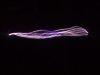


 . Its easy to get excited when the primary feels just warm and didnt burn your hand, hooray! Id challenge you to run the thing for 10 minutes straight and re-check the temp.