If you need assistance, please send an email to forum at 4hv dot org. To ensure your email is not marked as spam, please include the phrase "4hv help" in the subject line. You can also find assistance via IRC, at irc.shadowworld.net, room #hvcomm.
Support 4hv.org!
Donate:
4hv.org is hosted on a dedicated server. Unfortunately, this server costs and we rely on the help of site members to keep 4hv.org running. Please consider donating. We will place your name on the thanks list and you'll be helping to keep 4hv.org alive and free for everyone. Members whose names appear in red bold have donated recently. Green bold denotes those who have recently donated to keep the server carbon neutral.
Special Thanks To:
Aaron Holmes
Aaron Wheeler
Adam Horden
Alan Scrimgeour
Andre
Andrew Haynes
Anonymous000
asabase
Austin Weil
barney
Barry
Bert Hickman
Bill Kukowski
Blitzorn
Brandon Paradelas
Bruce Bowling
BubeeMike
Byong Park
Cesiumsponge
Chris F.
Chris Hooper
Corey Worthington
Derek Woodroffe
Dalus
Dan Strother
Daniel Davis
Daniel Uhrenholt
datasheetarchive
Dave Billington
Dave Marshall
David F.
Dennis Rogers
drelectrix
Dr. John Gudenas
Dr. Spark
E.TexasTesla
eastvoltresearch
Eirik Taylor
Erik Dyakov
Erlend^SE
Finn Hammer
Firebug24k
GalliumMan
Gary Peterson
George Slade
GhostNull
Gordon Mcknight
Graham Armitage
Grant
GreySoul
Henry H
IamSmooth
In memory of Leo Powning
Jacob Cash
James Howells
James Pawson
Jeff Greenfield
Jeff Thomas
Jesse Frost
Jim Mitchell
jlr134
Joe Mastroianni
John Forcina
John Oberg
John Willcutt
Jon Newcomb
klugesmith
Leslie Wright
Lutz Hoffman
Mads Barnkob
Martin King
Mats Karlsson
Matt Gibson
Matthew Guidry
mbd
Michael D'Angelo
Mikkel
mileswaldron
mister_rf
Neil Foster
Nick de Smith
Nick Soroka
nicklenorp
Nik
Norman Stanley
Patrick Coleman
Paul Brodie
Paul Jordan
Paul Montgomery
Ped
Peter Krogen
Peter Terren
PhilGood
Richard Feldman
Robert Bush
Royce Bailey
Scott Fusare
Scott Newman
smiffy
Stella
Steven Busic
Steve Conner
Steve Jones
Steve Ward
Sulaiman
Thomas Coyle
Thomas A. Wallace
Thomas W
Timo
Torch
Ulf Jonsson
vasil
Vaxian
vladi mazzilli
wastehl
Weston
William Kim
William N.
William Stehl
Wesley Venis
The aforementioned have contributed financially to the continuing triumph of 4hv.org. They are deserving of my most heartfelt thanks.
Registered Member #30
Joined: Fri Feb 03 2006, 10:52AM
Location: Glasgow, Scotland
Posts: 6706
Hi guys,
Finn, I didn't mean to dis your implementation of the N/P circuit. I think it's pretty good as implementations of it go: I've seen a few builders of it who didn't understand any of the issues raised in this thread, and came to the (old) forum with questions like, "It draws 12 amps from the supply, I lose AM radio reception and the MOSFETs catch fire, what am I doing wrong?"
It's the circuit itself I have the issue with, not your implementation. If you keep tweaking it carefully, I'm sure it'll work fine.
About the Odin gate drivers, they're not going anywhere
Registered Member #205
Joined: Sat Feb 18 2006, 11:59AM
Location: Skørping, Denmark
Posts: 741
Steve, all,
Thanks for saying that, Steve. But hey guys! I think we are having a blast here, good shop humor. I am not offended in any way, only pretending in an attempt to play funny. It's ok with a slightly rough tone, I can handle that.
Now, The Ghetto driver, the hack! Present status is as sitting on the bench, screwed onto a presumably good CM600 , and undergoing examination of key waveforms. The tek P6021/134 is monitoring current between MosFets, which means it monitors shoot trough when gate voltage drops (as if there was any), and current into gate when gate voltage rises.
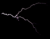
And as such, here is the big picture: Yellow is gate voltage on CM600, -10V/+20V, 1Volt overshoot, no gate resistor. Magentha is signal into optocoupler.
But let's have a closer look. On the rising edge of the CM600 gate voltage, you can see that voltage is being ramped up from -10V to -2V over 200nS, and then it shoots up to +20V in 100nS. No ringing but 1V overshoot. No gate resistor. No miller plateou Current is green, 4A/div, peaks @10A. Cyan is signal out of opto.
The delay is massive, 300nS for the opto to react, another 300nS for the totem pole to switch, total: 600nS from gate signal into opto, before the CM600 is on. More about this later.
On the falling edge:
Again, no ringing but delays are: 400nS for the opto to react, 300nS for the totem pole to switch, in all 700nS delay.
The delays are the drawbacks of this driver, and would render it useless in any other DRSSTC but this one: I can dial this delay in when I set the predikter. The neat thing is that it switches very cleanly, there are no ringing worth mentioning, no overshoot and no gate resistor to tame things. A word like synergy comes to mind, byt I am probably just talking rubbish. During the day, I have logged 5 hours of continous CW on it, and it runs slightly hot under CW conditions, which means that in pulsed mode it will run stone cold. I think I'l use it despite the delays but due to the clean switching and because I designed it myself.
Registered Member #289
Joined: Mon Mar 06 2006, 10:45AM
Location: Conroe, TX
Posts: 154
Those are some great looking waveforms, and that's a nice dense layout. I can't wait to see how this all plays out once the coil is running. What did you have in mind for a high side PS? Also, I have to agree with the Dr., I use 200V FETs where ever possible simply for higher reliability and transient ruggedness. I know your using 100V parts here, they will probably be fine, especially with such tame switching speeds.
Just for the purposes of comparison, here are a few waveforms I pulled out of my "archive" from my off line gate driver driving a CM1000.
Blue trace is drive input Green trace is the gate of the CM1000 at 5V/div
Note the overshoot from the small, but still there, leakage L of my custom 9:1:1:1:1 GDT. This is a problem you certainly don't have
Here we see the rise time, about 100ns to zero, 25ns to the miller, and another 75ns to the top (just barely clipped on the screen). The delay appears to be about 150ns. The circuit was designed specifically to keep this delay as small as possible since the parts where already so slow.
Not quite as pretty as yours, but considering the 220nF gate capacitance, I was very happy with these results I should also note that these screen shots where taken while the system was running at low power (about 5KW).
Registered Member #205
Joined: Sat Feb 18 2006, 11:59AM
Location: Skørping, Denmark
Posts: 741
Aron,
Thanks for posting your gate waveforms. I have often missed those to compare my work with the reality of others. Are you averaging the signal to clean the trace up? Mine are a bit more fuzzy. Going to be interesting to see how they react to a CM600 under load. High side PSU?. I guess a Mazilli and a flyback core, like on the CCPS. It works well, and is not too stiff, so the V-Reg. Zeners stay cool. Daniel is going to get the first prototype predikter board for a coil he is building for his work at Aalborg University, and it will be driving an intermediate full bridge, to drive the SKM 400GB124D power bridge. So we may be seing the first results on that coil. I have just started drilling the heatsink for the CM600 bridge, so it will soon be available for preliminary testing. Jeez, can't wait to be able to pass 1+kA without worrying about the bridge failing due to over current. I am also awfully tempted to buy one of these: So if you would please all step back and don't bid against me
Registered Member #289
Joined: Mon Mar 06 2006, 10:45AM
Location: Conroe, TX
Posts: 154
No problem, Finn. I often whish people would post more waveforms as well. Hopefully the proliferation of inexpensive (relatively) DSO's will help with that in the coming years.
That’s a good question. I do not have anything about it in my notes, but I may have had the bandwidth limit on.
I figured you would go that route for the high side; that driver is just sooo simple, it's really perfect for the task.
Ya, big systems are nice. I have been so much happier with my coils since I started running only 1200V parts and only running them within their DS ratings. I haven't had an IGBT failure in a DRSSTC in at least two years (I think the giant coil was the last one. That $1,100 brick hurt!).
Good luck with that monster inverter assembly. I can only imagine what the came from
Registered Member #123
Joined: Fri Feb 10 2006, 12:58PM
Location:
Posts: 162
Very informative thread. I think I have understood a little of it at least;-)
Your work is always very thorough Finn and you always strike me as a very organised thinker. (based on your help with my DRSSTC lash up that year at derby)
Keep up the good work while I try and make sense of it all
Registered Member #639
Joined: Wed Apr 11 2007, 09:09PM
Location: The Netherlands, Herkenbosch
Posts: 512
It's indeed a very good informational thread. Think I'll borrow a few things from this thread for my own DRSSTC. Starting to understand the various gate drives and the pros and cons of each type. Though I'm curious to see how much you'd need to slow down the gate driver when driving large slow bricks. Fast isn't always the best option.
But I'm really curious to see how well the delay circuit works and how sensitive it is.
Registered Member #205
Joined: Sat Feb 18 2006, 11:59AM
Location: Skørping, Denmark
Posts: 741
Thanks a lot folks, you are being very kind.
I am riding high on a surge of gumption and creativity. Today, I have been making the bus for the bridge, which is now starting to take shape:
In my urge to tuck the lytics as close as possible into the bridge, I had to do a lot of machining, and next time, the buss plates are going to be extended to both sides, and the caps are going to be mounted vertical instead of horisontal.
The gate drivers have been completed, and they open the gates "blixt schnell" 200nS and we will see if it is good or bad. Pls. note, that with the "Predikter", there is no need to slow down the turn on for the traditional reason: to allow the other IGBT to shut off. This design features separate timing for the turn off as well as the turn on, and the turn off happens at current zero crossing, right? So a completely new situation here.
The air core coil forming the predictor information in the load for the current transformer has now been replaced by a 1µH high class magnetically shielded part from Epcos, and it is working flawlessly.
Nice little 10mm x 10mm footprint SMD part.
I've got 3 days off, next week, so lots of progress is anticipated.
Registered Member #639
Joined: Wed Apr 11 2007, 09:09PM
Location: The Netherlands, Herkenbosch
Posts: 512
Your H-bridge looks great nice and compact. It would give me nightmares if I had to use single IGBT modules. Halfbridge modules together with some angle iron give a way simpler layout. I also had the urge to mount my lyctics sideways and almost on the igbt's
This site is powered by e107, which is released under the GNU GPL License. All work on this site, except where otherwise noted, is licensed under a Creative Commons Attribution-ShareAlike 2.5 License. By submitting any information to this site, you agree that anything submitted will be so licensed. Please read our Disclaimer and Policies page for information on your rights and responsibilities regarding this site.


 "Thumper"