If you need assistance, please send an email to forum at 4hv dot org. To ensure your email is not marked as spam, please include the phrase "4hv help" in the subject line. You can also find assistance via IRC, at irc.shadowworld.net, room #hvcomm.
Support 4hv.org!
Donate:
4hv.org is hosted on a dedicated server. Unfortunately, this server costs and we rely on the help of site members to keep 4hv.org running. Please consider donating. We will place your name on the thanks list and you'll be helping to keep 4hv.org alive and free for everyone. Members whose names appear in red bold have donated recently. Green bold denotes those who have recently donated to keep the server carbon neutral.
Special Thanks To:
Aaron Holmes
Aaron Wheeler
Adam Horden
Alan Scrimgeour
Andre
Andrew Haynes
Anonymous000
asabase
Austin Weil
barney
Barry
Bert Hickman
Bill Kukowski
Blitzorn
Brandon Paradelas
Bruce Bowling
BubeeMike
Byong Park
Cesiumsponge
Chris F.
Chris Hooper
Corey Worthington
Derek Woodroffe
Dalus
Dan Strother
Daniel Davis
Daniel Uhrenholt
datasheetarchive
Dave Billington
Dave Marshall
David F.
Dennis Rogers
drelectrix
Dr. John Gudenas
Dr. Spark
E.TexasTesla
eastvoltresearch
Eirik Taylor
Erik Dyakov
Erlend^SE
Finn Hammer
Firebug24k
GalliumMan
Gary Peterson
George Slade
GhostNull
Gordon Mcknight
Graham Armitage
Grant
GreySoul
Henry H
IamSmooth
In memory of Leo Powning
Jacob Cash
James Howells
James Pawson
Jeff Greenfield
Jeff Thomas
Jesse Frost
Jim Mitchell
jlr134
Joe Mastroianni
John Forcina
John Oberg
John Willcutt
Jon Newcomb
klugesmith
Leslie Wright
Lutz Hoffman
Mads Barnkob
Martin King
Mats Karlsson
Matt Gibson
Matthew Guidry
mbd
Michael D'Angelo
Mikkel
mileswaldron
mister_rf
Neil Foster
Nick de Smith
Nick Soroka
nicklenorp
Nik
Norman Stanley
Patrick Coleman
Paul Brodie
Paul Jordan
Paul Montgomery
Ped
Peter Krogen
Peter Terren
PhilGood
Richard Feldman
Robert Bush
Royce Bailey
Scott Fusare
Scott Newman
smiffy
Stella
Steven Busic
Steve Conner
Steve Jones
Steve Ward
Sulaiman
Thomas Coyle
Thomas A. Wallace
Thomas W
Timo
Torch
Ulf Jonsson
vasil
Vaxian
vladi mazzilli
wastehl
Weston
William Kim
William N.
William Stehl
Wesley Venis
The aforementioned have contributed financially to the continuing triumph of 4hv.org. They are deserving of my most heartfelt thanks.
Registered Member #1779
Joined: Sat Oct 25 2008, 11:05AM
Location:
Posts: 32
Do you also remove the big capacitor as well
And the diodes you use for the multiplier is that the ones you remove from the circuit. Also do you have to solder a wire to the metal push switch to keep it running?
Sorry for all these questions, but what happens if the diode connecting to the transformer is not on the grey strip. iE the The other side. The transformer does not connect to the grey strip side but the other side of the diode
Registered Member #952
Joined: Mon Aug 13 2007, 11:07AM
Location: Finland
Posts: 388
hydraliskdragon wrote ...
What do you think is the estimated price for all the component?
I'd say 5-10$ depending on where you get your caps and diodes for the multiplier. I got mine from used disposable cameras, but you'll have to get many of them.
fatboyslim wrote ...
Do you also remove the big capacitor as well
You can remove it, however it doesn't matter as it's already isolated from the charging circuit as the diode is removed.
fatboyslim wrote ...
And the diodes you use for the multiplier is that the ones you remove from the circuit.
Yes, you'll have to get many of those camera flash boards.
fatboyslim wrote ...
Also do you have to solder a wire to the metal push switch to keep it running?
Yes, I forgot to add it to the tutorial.
fatboyslim wrote ...
Sorry for all these questions, but what happens if the diode connecting to the transformer is not on the grey strip. iE the The other side. The transformer does not connect to the grey strip side but the other side of the diode
It's ok, your circuit has positive output as some other circuits have negative output. However, it doesn't matter on this circuit. Do as told on the tutorial.
Oh, and please avoid double posting. It's against the forum rules.
Heck, I'm very surprised by the popularity of this little circuit. Maybe I should seriously think of making a revision of the tutorial. And a brand new coil, too! But it's very hard to make a one-for-all tutorial as there are many different types of camera flash circuits.
Registered Member #1733
Joined: Thu Oct 02 2008, 03:17PM
Location: Hamilton, ON, Canada
Posts: 100
Why are you supprised? This is a fantastic "mini" project. I built a 10" SGTC, and it works very well. I just can't take it to work. Enter the "micro" SGTC from camera parts. I got 33 used cameras from a photo place and am in the process of building 2 little ones, with some modifications.
I'm putting everything in a "project box", adding a 2P2T switch, and a 3.3v 500ma wallwart. I can use the batteries or wallwart. I just don't want to eat dozens of batteries demo-ing the TC.
In your original photos, you had completly disassembled the boards, and were only using the parts needed. Do you have a schematic of that setup? Even with the diode removed from the HV lead on the xfmr, there is still power being leached into the rest of the board (evident with the LED lighting up)
Registered Member #952
Joined: Mon Aug 13 2007, 11:07AM
Location: Finland
Posts: 388
Zenador wrote ...
In your original photos, you had completly disassembled the boards, and were only using the parts needed. Do you have a schematic of that setup? Even with the diode removed from the HV lead on the xfmr, there is still power being leached into the rest of the board (evident with the LED lighting up)
There are many types of disposable camera flash boards, mine were from blue Fujifilm cameras. Here is a schematic which most closely represents the circuit in those ones. Just look at the leftmost parts (not including the diode) and you'll figure it out. It's just the transformer, resistor and transistor. For different types of boards, a Google search for "disposable camera schematic" will return many different pages with different schematics. They seem to vary brand by brand, but I've even seen two different Fujifilm ones! If you still can't find a suitable schematic, you must do a bit 'reverse-engineering' to figure out the parts and the schematic which are driving the transformer.
One important note to anyone who is going to build this: Use commercial capacitors! Homemade caps just leak out the tiny bit of power coming from the little transformers.
Registered Member #1733
Joined: Thu Oct 02 2008, 03:17PM
Location: Hamilton, ON, Canada
Posts: 100
So I finished my "micro" SGTC yesterday. This is the first or many (family/friends are asking for one now...)
I have to say, well done Dr. 2N3055 on your descriptions for building this little guy. I think the biggest pain in the build was the CW multiplier - those little caps just do not want to sit still to solder them together...
changes and results...
6 turns 1mm wire 120mm x 15mm secondary (32AWG magnet wire) (former was the tube you get solder in) Three 1"x1/16" aluminum crush washers soldered together to make a top load. Two 2kV 300pF MMC (parallel - series made it worse) 1.5mm spark gap.
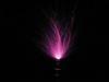
I get about 4mm discharges, and continuous arcs just about an inch. The arcs are visible in a lighted room, which was important to me - I had to demo it at my desk at work today...
If you have any other uses for those flash boards, post them up, I have another 30 I can play with....
Registered Member #1779
Joined: Sat Oct 25 2008, 11:05AM
Location:
Posts: 32
Hay, sorry for double posting. I just got my camera circuit and i got 1386 volts from ONE BATTERY! When i wired the CW multiplier and attached it to the camera circuit nothing happened. Is this because my camera circuit needs a negative multiplier instead of a positive one. The one shown in your tutorial is a positive multiplier according to Ive hit a wall right now and im unsure what to do. Could the problem be with my multiplier. The diodes i used are from the kodak circuit which are IF16 diodes. Should i use UF4007 or can i use IN4007 instead?
Registered Member #1733
Joined: Thu Oct 02 2008, 03:17PM
Location: Hamilton, ON, Canada
Posts: 100
Fatboyslim - Where did you measure the voltage? 1.3kV is too high (IMO) from the big xfmr. That make more sense from the secondary (smaller) xfmr. The smaller one is connected to the copper plate behind the flash bulb to ionize the gas.
From one AA or AAA battery, the larger xfmr should output ~300V. I have 33 disposable flash boards, and they all read roughly the same.
Your board is generating +HV from the large xfmr based on your description of the diode in relation to the outputs. Same as most of mine. Remove the diode completely from the board. The side where the gray stripe was is negative (common) - wire it to the common (-)(GND) of the CW, batteries, everything common. The non-striped side (connected to the large xfmr on the PCB) is the +HV which is wired to the + on the CW.
In my build, all common wires are really common, battery, xfmr, CW, SG, they are all connected. If the common on the CW is NOT connected to the negative (common) of everything else, it still works, just very very slowly. The SG fires only twice a second, so the oscillation is to slow to do anything useful. Properly wired, it works just like a full sized TC, just on a small scale.
Registered Member #1779
Joined: Sat Oct 25 2008, 11:05AM
Location:
Posts: 32
the second pin from the 3 pin side of the transformer connects on to the grey side of the diode. I removed the diode and soldered a wire to the grey strip side. I measured the voltage from the wire and the negative side of the battery. This gave me the 1.3kv. Where should i read the voltage from? Do i have to have two wires from where the diode used to be? and that is my negative and my positive. I am currently using a fujifilm circuit.
Registered Member #1733
Joined: Thu Oct 02 2008, 03:17PM
Location: Hamilton, ON, Canada
Posts: 100
fatboyslim wrote ...
the second pin from the 3 pin side of the transformer connects on to the grey side of the diode.
Ok, Grey side of the diode to the xfmr is negative HV out.
fatboyslim wrote ...
I removed the diode and soldered a wire to the grey strip side. I measured the voltage from the wire and the negative side of the battery. This gave me the 1.3kv. Where should i read the voltage from?
Voltage should be measured from xfmr to positive terminal of the battery (I think) on your board.
fatboyslim wrote ...
Do i have to have two wires from where the diode used to be? and that is my negative and my positive. I am currently using a fujifilm circuit.
Black wire to the grey side where the diode used to be, red wire to the other hole. The CW Multiplier also needs to be built correctly. There are positive CW-M and negative CW-M. Difference is diode direction.
This site is powered by e107, which is released under the GNU GPL License. All work on this site, except where otherwise noted, is licensed under a Creative Commons Attribution-ShareAlike 2.5 License. By submitting any information to this site, you agree that anything submitted will be so licensed. Please read our Disclaimer and Policies page for information on your rights and responsibilities regarding this site.


 Small Tesla Coil using disposable camera transformers
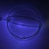


