If you need assistance, please send an email to forum at 4hv dot org. To ensure your email is not marked as spam, please include the phrase "4hv help" in the subject line. You can also find assistance via IRC, at irc.shadowworld.net, room #hvcomm.
Support 4hv.org!
Donate:
4hv.org is hosted on a dedicated server. Unfortunately, this server costs and we rely on the help of site members to keep 4hv.org running. Please consider donating. We will place your name on the thanks list and you'll be helping to keep 4hv.org alive and free for everyone. Members whose names appear in red bold have donated recently. Green bold denotes those who have recently donated to keep the server carbon neutral.
Special Thanks To:
Aaron Holmes
Aaron Wheeler
Adam Horden
Alan Scrimgeour
Andre
Andrew Haynes
Anonymous000
asabase
Austin Weil
barney
Barry
Bert Hickman
Bill Kukowski
Blitzorn
Brandon Paradelas
Bruce Bowling
BubeeMike
Byong Park
Cesiumsponge
Chris F.
Chris Hooper
Corey Worthington
Derek Woodroffe
Dalus
Dan Strother
Daniel Davis
Daniel Uhrenholt
datasheetarchive
Dave Billington
Dave Marshall
David F.
Dennis Rogers
drelectrix
Dr. John Gudenas
Dr. Spark
E.TexasTesla
eastvoltresearch
Eirik Taylor
Erik Dyakov
Erlend^SE
Finn Hammer
Firebug24k
GalliumMan
Gary Peterson
George Slade
GhostNull
Gordon Mcknight
Graham Armitage
Grant
GreySoul
Henry H
IamSmooth
In memory of Leo Powning
Jacob Cash
James Howells
James Pawson
Jeff Greenfield
Jeff Thomas
Jesse Frost
Jim Mitchell
jlr134
Joe Mastroianni
John Forcina
John Oberg
John Willcutt
Jon Newcomb
klugesmith
Leslie Wright
Lutz Hoffman
Mads Barnkob
Martin King
Mats Karlsson
Matt Gibson
Matthew Guidry
mbd
Michael D'Angelo
Mikkel
mileswaldron
mister_rf
Neil Foster
Nick de Smith
Nick Soroka
nicklenorp
Nik
Norman Stanley
Patrick Coleman
Paul Brodie
Paul Jordan
Paul Montgomery
Ped
Peter Krogen
Peter Terren
PhilGood
Richard Feldman
Robert Bush
Royce Bailey
Scott Fusare
Scott Newman
smiffy
Stella
Steven Busic
Steve Conner
Steve Jones
Steve Ward
Sulaiman
Thomas Coyle
Thomas A. Wallace
Thomas W
Timo
Torch
Ulf Jonsson
vasil
Vaxian
vladi mazzilli
wastehl
Weston
William Kim
William N.
William Stehl
Wesley Venis
The aforementioned have contributed financially to the continuing triumph of 4hv.org. They are deserving of my most heartfelt thanks.
Registered Member #1223
Joined: Thu Jan 10 2008, 04:32PM
Location:
Posts: 133
Same happened again as always for me. It seemed to work just fine at 110V supplyvoltage. IGBT's and freewheeling diodes didnt get hot, just slightly warm. Inverter voltage vs. current: http://www.elisanet.fi/tonskulus/inverter_out.jpg
And then, i decided to try this at full 220V supply voltage. I also added more inductance for zmatch to keep supply current at reasonable level, still 5..7Amps. It didnt last even one minute before igbt failure happened. Both were shorted. Is it possible that some shoottrough happened there for some reason? I had always the same problem with halfbridges driven at >100Volt supply. they wont suffer.
Registered Member #1232
Joined: Wed Jan 16 2008, 10:53PM
Location: Doon tha Toon!
Posts: 881
Although the devices died cold, shoot-through seems unlikely as there would be a lot of noise on the voltage waveform. Diode reverse recovery problems also seem unlikely as ringing on the current waveform suggests switching takes place before the current zero-crossing.
The voltage waveform looks strange though: Rounded leading edges and almost a 60% voltage overshoot! This may be exceeding the rating of your switches at the peaks of the supply voltage. That cosine shaped wiggle on top of the inverter voltage waveform (which should be flat) is usually indicative of excessive inductance in the DC bus wiring to the inverter. Try adding more capacitance across the DC bus right where the IGBT's are located.
Have you checked what your gate drive waveforms look like at the IGBTs during operation? It's also worth checking that your x10 (or x100) scope probes are correctly compensated before making these high-frequency measurements.
Registered Member #1223
Joined: Thu Jan 10 2008, 04:32PM
Location:
Posts: 133
I just noticed that there is overshooting problem. Without load at all (inverter output open), there is still current going through igbts. 200mA or so. I did try adding 10µF capacitor to the DC supply rail and it helped smoothing invertrer voltage.: http://www.elisanet.fi/tonskulus/ih/volts.jpg
Registered Member #1232
Joined: Wed Jan 16 2008, 10:53PM
Location: Doon tha Toon!
Posts: 881
That output waveform looks a lot better now.
With no load on the output of a half-bridge (or full bridge) you always get some current drawn from the supply, particularly when running at high frequency and high voltage. This 200mA current does not necessarily indicate shoot-through due to conduction overlap in the IGBTs. It may just represent the power required to charge and discharge the output capacitances of your switching devices.
(The power dissipated to charge/discharge device capacitances alone can get high for large die devices at high frequencies and high supply voltages. Eliminating this loss is the main motivation behind ZVS schemes like Class E, etc in power electronics.)
Registered Member #1223
Joined: Thu Jan 10 2008, 04:32PM
Location:
Posts: 133
Ok, i have been running this inverter today for a while with new igbts. Everything seems to be ok at 110Volts. I pushed this to the limits, 15Amps input current and no problems. But im sure it blows up if i switch to 220V. Thats what it always does. Yesterday I was running off 110Volts / 10Amps and decided to switch 220V. IGBT failure happened at only 4Amp supply current.
Registered Member #1217
Joined: Mon Jan 07 2008, 11:46AM
Location: Leicester, UK
Posts: 11
Hi Tonskulus, Well done. Looks ok. The waveforms are either shoot-through or too much inductance on the low side drain- otherwise it should be working by now. Scrap that 10u cap though- the waveforms are fine. Geordie Boy hasn't realised the reason for the dodgy looking waveform- its is tracking the mains voltage. ....UPDATE- Yes he did! He has added a thread just after I posted this....This keeps your power factor high. I get 0.99 PF which is as good as a comercial unit!
Shame about the IGBT failures though- just looked at your other waveforms. The 10u won't solve shoot through it will just damp the ringing frequency. You need a dead time- I use 500ns ant 120khz- its high but seems to work reliably. You have some high frequency ringing on the collectors that looks suspicious- look for stray inductance. Finally make sure your oscillator is far from the work coil and shielded and the current feedback to the oscillator is minimal- current transformer saturation led to early unexplained failures for me.
Hi Steve, Awsome idea about the little cap to drop the current- Better than my solution. As for ZCS, it only occurs at high currents with low work coil loading. The work coild current is supperimposed onto bridge output by the ratio on the coil inductance to the inductor. If i have a small inductor i can get good zcs but high device currents. If I have a large inductor my current is almost triangular all the time. My ratio is 10-20 to 1 deppending what power i want.
Geordie Boy, the 3 kW low load power goes like this... all approx- 70w into switches, 100w into inductor (resisitive), 135w into my caps and the rest into water heating through resistive work coil losses (no work piece)- water goes in at 15 degrees and comes out at 70!
Registered Member #1232
Joined: Wed Jan 16 2008, 10:53PM
Location: Doon tha Toon!
Posts: 881
Tonskulus: For debugging unexplained failures it helps if you can run it from a regulated adjustable DC supply to remove the 100Hz envelope blurring. Wind the voltage up slowly towards 340VDC whilst watching all the waveforms on a scope. The clues are there!
At the risk of getting my backside kicked for turning this thread into a lesson on inverter testing I'll leave it there.
Registered Member #1223
Joined: Thu Jan 10 2008, 04:32PM
Location:
Posts: 133
Without 10µF DC filtering cap there are huge amounts of ringing at inverter output! Anyway, im using 50Amp IGBT brick instead of HGTG30N60xx's. It drives ok at 100kHz. I have to get rid of some stray inductances and make a shield for oscillator/driverboard if it helps, just like Kim told me to do. I'll keep working :)
Registered Member #1223
Joined: Thu Jan 10 2008, 04:32PM
Location:
Posts: 133
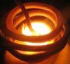
Finally Im able to melt some steel parts with this thing. Still 110Volt supply is used as it seems to work reliable now, I have no reason for higher input voltages to be used. Not for this one..maybe I can make another system for higher powerlevels later but its another story then. Ok, I made a short video about bolt being melted. Input voltage 110Volts and current 10..15Amps, 20A is maximum (limited by isolation trafo).
This site is powered by e107, which is released under the GNU GPL License. All work on this site, except where otherwise noted, is licensed under a Creative Commons Attribution-ShareAlike 2.5 License. By submitting any information to this site, you agree that anything submitted will be so licensed. Please read our Disclaimer and Policies page for information on your rights and responsibilities regarding this site.


 OMG Induction Heater