If you need assistance, please send an email to forum at 4hv dot org. To ensure your email is not marked as spam, please include the phrase "4hv help" in the subject line. You can also find assistance via IRC, at irc.shadowworld.net, room #hvcomm.
Support 4hv.org!
Donate:
4hv.org is hosted on a dedicated server. Unfortunately, this server costs and we rely on the help of site members to keep 4hv.org running. Please consider donating. We will place your name on the thanks list and you'll be helping to keep 4hv.org alive and free for everyone. Members whose names appear in red bold have donated recently. Green bold denotes those who have recently donated to keep the server carbon neutral.
Special Thanks To:
Aaron Holmes
Aaron Wheeler
Adam Horden
Alan Scrimgeour
Andre
Andrew Haynes
Anonymous000
asabase
Austin Weil
barney
Barry
Bert Hickman
Bill Kukowski
Blitzorn
Brandon Paradelas
Bruce Bowling
BubeeMike
Byong Park
Cesiumsponge
Chris F.
Chris Hooper
Corey Worthington
Derek Woodroffe
Dalus
Dan Strother
Daniel Davis
Daniel Uhrenholt
datasheetarchive
Dave Billington
Dave Marshall
David F.
Dennis Rogers
drelectrix
Dr. John Gudenas
Dr. Spark
E.TexasTesla
eastvoltresearch
Eirik Taylor
Erik Dyakov
Erlend^SE
Finn Hammer
Firebug24k
GalliumMan
Gary Peterson
George Slade
GhostNull
Gordon Mcknight
Graham Armitage
Grant
GreySoul
Henry H
IamSmooth
In memory of Leo Powning
Jacob Cash
James Howells
James Pawson
Jeff Greenfield
Jeff Thomas
Jesse Frost
Jim Mitchell
jlr134
Joe Mastroianni
John Forcina
John Oberg
John Willcutt
Jon Newcomb
klugesmith
Leslie Wright
Lutz Hoffman
Mads Barnkob
Martin King
Mats Karlsson
Matt Gibson
Matthew Guidry
mbd
Michael D'Angelo
Mikkel
mileswaldron
mister_rf
Neil Foster
Nick de Smith
Nick Soroka
nicklenorp
Nik
Norman Stanley
Patrick Coleman
Paul Brodie
Paul Jordan
Paul Montgomery
Ped
Peter Krogen
Peter Terren
PhilGood
Richard Feldman
Robert Bush
Royce Bailey
Scott Fusare
Scott Newman
smiffy
Stella
Steven Busic
Steve Conner
Steve Jones
Steve Ward
Sulaiman
Thomas Coyle
Thomas A. Wallace
Thomas W
Timo
Torch
Ulf Jonsson
vasil
Vaxian
vladi mazzilli
wastehl
Weston
William Kim
William N.
William Stehl
Wesley Venis
The aforementioned have contributed financially to the continuing triumph of 4hv.org. They are deserving of my most heartfelt thanks.
Registered Member #30
Joined: Fri Feb 03 2006, 10:52AM
Location: Glasgow, Scotland
Posts: 6706
CS, this is beautiful! I can't believe you even made a vintage-looking line cord. Where did you get a brown IEC connector, or did you paint one? Anyway, I can't wait to see it working!
Registered Member #397
Joined: Wed Apr 19 2006, 12:56AM
Location: Western Washington
Posts: 125
I painted the IEC connector. I would absolutely kill for a real brown one! I tried hard but couldn't find anything like it. The brown krylon I used isn't holding up well so I'll have to look for something else. I guess the plastic is kind of oily or something. Making the mains cord was fun.
The brass spheres are pre-tapped and threaded units I buy from toolsupply on ebay.
Brass hardware like nuts and bolts are purchased at Home Depot in small quantities but I feed off large purchases at McMaster Carr. It is actually cheaper to buy in 100pc bulk at McMaster than the nickel/dime bags at the local hardware store, but it requires a larger financial investment up front. I bought my threaded thumbscrews, brass and copper washers, and some bolts through McMaster. Since I don't know what length I need, I ended up buying longer bolts and cutting down the length to what I need. Cheaper than buying multiple boxes in 1/4" increments.
I got the larger diameter "end caps" came from an insanely expensive internet store called Grand Brass Lamp Parts. I would never buy there again (shipping was $20 on top of the insane prices. I think my order ended up being $60 for 8pcs plus the adapters). No other stores had what I need though and a redesign would require changing the diameter of the standoffs that make the pillars (which would be even more expensive). If I had a lathe...this would all be much easier/cheaper!
Registered Member #1497
Joined: Thu May 22 2008, 05:24AM
Location: Toronto, Ontario, Canada
Posts: 801
Cesiumsponge: Try taking a new clean IEC connector and using vinyl dye instead. Its like spray paint but its meant for plastics.
- Take a new clean connector, dump it in isopropyl alcohol to clean it, let it dry. (and handle with gloves from this point onwards) - Hang the connector by one of the solder tabs, mask off all the metal parts - Spray, dry, check for any thin/uncoated portions, recoat if neccessary - Dry and bake if neccessary (depending on the vinyl dye instructions, it might take a while for it to fully dry).
Registered Member #397
Joined: Wed Apr 19 2006, 12:56AM
Location: Western Washington
Posts: 125
A small update. There are a lot more fine details but I have been getting lazy and tired due to the warm weather and life in general. I'm nearing the end of this project and I have a four-day weekend coming up and I intend to do most, if not all the remaining work then.
I wired up most of my ground wire runs into bundles but haven't photographed them yet since I need to take apart the top deck to get good photos. I need to finalize terminations and then cable lace them together. Every other bit of wiring is done other than that and the primary/feedback coil is in place, including installation of all feedthroughs.
I finished my grid leak resistor assembly today. The design changed quite a bit from the initial inception and it got overly complex for the sake of aesthetic steampunky goodness but it has been completed and mounted. It is comprised of over 50 individual pieces.
It consists of three 0-3kohm variable resistors set in series. It's currently set at 1kohm each, giving 3kohm total, the same value I used for my previous coil. Each is rated at 50W dissipation and will be sufficient. The variability will give me flexibility in testing grid leak values.
They are sandwiched together with two pieces of brass, insulated with a phenolic spacer. The needlessly complex bracket is in place so that I can visually "wrap" the grid leak resistor around the curvature of the primary coil. The two bracket assemblies pivot at the axis through the resistor on either end and is tensioned with the knurled thumbnut up top. Each bracket is attached at the base of the assembly into the deck. I used copper bus material as my brackets and phenolic to tie the top and bottom brackets together. I used plenty of tapped brass spheres and knurled thumbscrews to continue the theme.
The mica cap seen in the photo next to it is the grid leak capacitor I will parallel with the resistor assembly to form the grid leak network.
aonomus wrote ...
Cesiumsponge: Try taking a new clean IEC connector and using vinyl dye instead. Its like spray paint but its meant for plastics.
- Take a new clean connector, dump it in isopropyl alcohol to clean it, let it dry. (and handle with gloves from this point onwards) - Hang the connector by one of the solder tabs, mask off all the metal parts - Spray, dry, check for any thin/uncoated portions, recoat if neccessary - Dry and bake if neccessary (depending on the vinyl dye instructions, it might take a while for it to fully dry).
How well does dye show up on a black plastic? Doesn't it require bleaching first?
Registered Member #397
Joined: Wed Apr 19 2006, 12:56AM
Location: Western Washington
Posts: 125
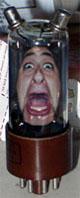
I finally had first light. I made a terrible assumption that the rectifier tube's symbol =(> |)--- is the same as the symbol for a diode -->|--. I assumed that the diode's schematic representation evolved from the tube rectifier symbol so they were identical. No, the cathode ended up being anode and anode was cathode. I actually ended up wiring my rectifier in reverse. That'll teach me to make assumptions! I spent some time redoing the wiring and re-lacing all the cables.
Everything except the primary and feedback coils are in their final state of assembly. I got sidetracked once I got first light so I spent the rest of the night tinkering with it instead of taking photos of the progress. I'll take pictures of the coil soon, possibly tomorrow.
Here is the grounding stuff all wired up and bundled, and the dressed-up IEC jack.
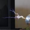
I'm going to start a thread on this since I seem to have some questions with proper tuning. Here are a couple of "wild" shots at 100-110VAC input. The sparks have lost linearity of the stereotypical "sword-like" appearance and branch out in an unpredictable manner. They're also quite hot. The linearity and sword-like appearance reappears once the voltage is turned down. I can't keep it running like this without having the plate start to get cherry red, though it can run indefinitely around 85-90V without any noticeable plate glow. They're right around 17" or so to a grounded sheet above the coil.
Registered Member #397
Joined: Wed Apr 19 2006, 12:56AM
Location: Western Washington
Posts: 125
The streamer colors vary a bit when captured on camera depending on other ambient lighting. The auto WB is usually fairly good at judging but if there is other lighting nearby, it'll make the streamers look much bluer. I had almost all the lights out when I took the last few images. For example, the first three images I have above are unnaturally bluish because I had a halogen and fluoro light in the shop on which caused the auto WB to shift the hue so the streamers turned out inaccurate in hue.
The primary on there right now just has some household wire making up the primary with lots of tape and ugly slits where I'm using a gator clip to experiment with taps. I ran out of vertical room on my workbench with a variable height grounded strike plate (replaced the suspended foil because it wasn't flat enough to get an accurate reading). About 1" above that is the steel rail that the garage door arm rides on so I tried moving my grounded strike plate out of the way for a direct strike to the garage door opener rail. I successfully made several streamer strikes to it at 120V (roughly one strike every 2-3 seconds) which puts the length at 19.25"!
Except the grid feedback was very unhappy and it arced across a good 6" of PVC primary coilform and ruined the primary coilform so now I can't use it because it'll arc at the slightest provocation. Also the plate was starting to incandesce a dull cherry red, indicating it isn't going to stay cool for much longer so it's definitely not a steramer length achieved under normal operational circumstances. This was at turn 33. I had charted 50-120V measurements from turn 30 to 33 up until my primary coilform crapped out.
I'll have to dig up another length of 6" PVC and prep it as a coilform.
Here is a no-nonsense overview of the coil as it stands right now, and also a picture of the arcover that has halted my process until it is fixed. The primary coilform can be fixed but the feedback coilform is toast...it charred that baby!
Here is a photo of the bleeder resistors I have for the voltage doubler capacitor bank.
This site is powered by e107, which is released under the GNU GPL License. All work on this site, except where otherwise noted, is licensed under a Creative Commons Attribution-ShareAlike 2.5 License. By submitting any information to this site, you agree that anything submitted will be so licensed. Please read our Disclaimer and Policies page for information on your rights and responsibilities regarding this site.


 The Tesla Thermionic Valve Wireless Energy Transmitting Apparatus
 I can't believe you even made a vintage-looking line cord. Where did you get a brown IEC connector, or did you paint one? Anyway, I can't wait to see it working!