If you need assistance, please send an email to forum at 4hv dot org. To ensure your email is not marked as spam, please include the phrase "4hv help" in the subject line. You can also find assistance via IRC, at irc.shadowworld.net, room #hvcomm.
Support 4hv.org!
Donate:
4hv.org is hosted on a dedicated server. Unfortunately, this server costs and we rely on the help of site members to keep 4hv.org running. Please consider donating. We will place your name on the thanks list and you'll be helping to keep 4hv.org alive and free for everyone. Members whose names appear in red bold have donated recently. Green bold denotes those who have recently donated to keep the server carbon neutral.
Special Thanks To:
Aaron Holmes
Aaron Wheeler
Adam Horden
Alan Scrimgeour
Andre
Andrew Haynes
Anonymous000
asabase
Austin Weil
barney
Barry
Bert Hickman
Bill Kukowski
Blitzorn
Brandon Paradelas
Bruce Bowling
BubeeMike
Byong Park
Cesiumsponge
Chris F.
Chris Hooper
Corey Worthington
Derek Woodroffe
Dalus
Dan Strother
Daniel Davis
Daniel Uhrenholt
datasheetarchive
Dave Billington
Dave Marshall
David F.
Dennis Rogers
drelectrix
Dr. John Gudenas
Dr. Spark
E.TexasTesla
eastvoltresearch
Eirik Taylor
Erik Dyakov
Erlend^SE
Finn Hammer
Firebug24k
GalliumMan
Gary Peterson
George Slade
GhostNull
Gordon Mcknight
Graham Armitage
Grant
GreySoul
Henry H
IamSmooth
In memory of Leo Powning
Jacob Cash
James Howells
James Pawson
Jeff Greenfield
Jeff Thomas
Jesse Frost
Jim Mitchell
jlr134
Joe Mastroianni
John Forcina
John Oberg
John Willcutt
Jon Newcomb
klugesmith
Leslie Wright
Lutz Hoffman
Mads Barnkob
Martin King
Mats Karlsson
Matt Gibson
Matthew Guidry
mbd
Michael D'Angelo
Mikkel
mileswaldron
mister_rf
Neil Foster
Nick de Smith
Nick Soroka
nicklenorp
Nik
Norman Stanley
Patrick Coleman
Paul Brodie
Paul Jordan
Paul Montgomery
Ped
Peter Krogen
Peter Terren
PhilGood
Richard Feldman
Robert Bush
Royce Bailey
Scott Fusare
Scott Newman
smiffy
Stella
Steven Busic
Steve Conner
Steve Jones
Steve Ward
Sulaiman
Thomas Coyle
Thomas A. Wallace
Thomas W
Timo
Torch
Ulf Jonsson
vasil
Vaxian
vladi mazzilli
wastehl
Weston
William Kim
William N.
William Stehl
Wesley Venis
The aforementioned have contributed financially to the continuing triumph of 4hv.org. They are deserving of my most heartfelt thanks.
Registered Member #543
Joined: Tue Feb 20 2007, 04:26PM
Location: UK
Posts: 4992
Dr. Shark wrote ...
Harry wrote ...
Unfortunately, I don't have access to the full text, but the statement suggests the reason why some designs add some extra windings to the active fast line and not the passive slow line.
You do now, check your PMs.
Thank you so much Dr Shark! Its amazing that such a simple device wasn't discovered until the 1960s, and that professional scientists were still trying to explain how it works in this 2003 paper.
I like to have as much understanding as I can before I start on a project, because I've wasted so much time and money in the past on building things which didn't work properly because I didn't understand all the principles involved.
Registered Member #75
Joined: Thu Feb 09 2006, 09:30AM
Location: Montana, USA
Posts: 711
Harry, I completely agree with you, especially after I essentially wasted most of last night constructing a bit of a dud. I already edited my above post to reflect my latest ideas, but I'll repeat: The only reference that claims an improved output with extra secondary turns is the 1984 patent Peter cited in his first post. This looks more like an ordinary transformer to me than a VIG, although the two are of course intimately interrelated. As I understand the VIG, there is a cycle of LC oscillation which reverses the voltage on the capacitor, so the energy has to be stored in the magnetic field as the voltage crosses zero. At this point, a voltage would be induced in the additional turns. Thus the "extended VIG" seems to be quite different from a normal VIG in its operating principle.
All other references I could find about VIGs just use a 1:1 turns ratio, so that is what I will try tonight. Rewinding my VIG is pretty straightforward, so I'll see if that helps and report back.
Registered Member #543
Joined: Tue Feb 20 2007, 04:26PM
Location: UK
Posts: 4992
Having got the paper thanks to our friend Dr Shark, and seen the information on the D/n ratio in Table 1, I feel able to begin a modest proof of concept model.
I've decided to use 75mm aluminium adhesive tape for the lines, and a double thickness of 100mm adhesive insulating tape as the dielectric, with a bundle of ferrite rods as the core.
I have the ferrite rods, but will have to send off to ebay for the aluminium tape and the extra-wide insulating tape, so won't be able to do anything in a hurry.
I've not made my mind up on the switch, but suppose I will go for a self-igniting spark gap to start with, which should be OK with a 3kV charge voltage from a Bertrand PSU I have to hand. I will charge a reservoir capacitor first, and power the VIG from that after disconnecting the supply, as I see from various patents that the EMP from VIGs can destroy electronic equipment nearby, or to which it is coupled, so it seems to me to need its own separate low Z earth.
Registered Member #75
Joined: Thu Feb 09 2006, 09:30AM
Location: Montana, USA
Posts: 711
I would not count on the pulses being that short, after all there is considerable inductance in the circuit from coiling up the transmission line. In the papers I looked at the discharge in in the order of a microsecond, which is not what I would call short.
Registered Member #543
Joined: Tue Feb 20 2007, 04:26PM
Location: UK
Posts: 4992
"The pulsewidth is equal to 2ntτt where nt is the number of turns and τt is the average one way propagation time for a single turn. If t = 0 represents the closing of the switch, the leading edge of the output pulse is delayed by an amount nt τt which for many applications is unimportant."
Source: Fast risetime spiral pulse generator United States Patent 4140917
For practical purposes, I would reckon on the real life pulse being perhaps twice as long as the theory.
The pulses are triangular, but they could always be sharpened with a spark gap if necessary.
Registered Member #10
Joined: Thu Feb 02 2006, 09:45AM
Location: Bunbury, Australia
Posts: 1424
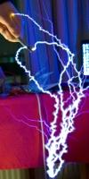
I have built a beefier setup. Specs Output... bright 1/2 inch (1.25cm) sparks (perhaps 15kV) Input..... 2.5kV peak. (ie 6 times voltage stepup) (NST 1/2 wave plus 1MOhm for testing). Foil........ Equal length copper foils 4.5cm x 243cm plus lead in. Former... 4.2 x 7cm. Ext diameter 6.2cm. Turns..... Calculated 14 turns Spark gap 1mm Core...... Ferrrite E cores to fit in 4cm gap. Cap....... 20 nF (prev one was 0.9nF) Insul...... Polyethylene groundsheet
So a better result with more turns and area. How long the dielectric lasts is unclear and also what increase in input voltage and power will it tolerate? Probably needs to be in oil for that.
Registered Member #543
Joined: Tue Feb 20 2007, 04:26PM
Location: UK
Posts: 4992
Great stuff, TDU.
I have this morning sent off for 75mm adhesive aluminium tape and 100mm insulating tape from ebay suppliers, so I should have a rig of my own to report on in a week or ten days.
I must say how glad I am you dug this up, and gave us all the opportunity to learn something out of the ordinary.
Registered Member #10
Joined: Thu Feb 02 2006, 09:45AM
Location: Bunbury, Australia
Posts: 1424
It's interesting to go down a new path. I've often wondered about impulse transformers although I guess this is only just one type. This new version seems to have scaled in spark brightness consistent with 20 times the capacitance and also scaled in output spark length 8mm to 12 mm consistent with the increased turns from 9 to 14. Construction type was similar and dielectric and input voltage were unchanged. The capacitor holds its charge well and if discharged with a chicken stick giving a reasonable "zap", will give an output spark as well. I suspect that for high repetition rates, the use of a multiple segment gap would prevent power arcing. I also suspect from my experience with TEA nitrogen lasers that the spark gap type and position is critical. The use of a gap with two cylindrical electrodes in continuity with each conductor strip and covering the full width should present the lowest inductance. As it is, I suspect it could be driven much harder than just a few pulses per second, but I am not ready to break it yet.
This site is powered by e107, which is released under the GNU GPL License. All work on this site, except where otherwise noted, is licensed under a Creative Commons Attribution-ShareAlike 2.5 License. By submitting any information to this site, you agree that anything submitted will be so licensed. Please read our Disclaimer and Policies page for information on your rights and responsibilities regarding this site.


 Spiral impulse generator = rolled cap Blumlein induction coil!