If you need assistance, please send an email to forum at 4hv dot org. To ensure your email is not marked as spam, please include the phrase "4hv help" in the subject line. You can also find assistance via IRC, at irc.shadowworld.net, room #hvcomm.
Support 4hv.org!
Donate:
4hv.org is hosted on a dedicated server. Unfortunately, this server costs and we rely on the help of site members to keep 4hv.org running. Please consider donating. We will place your name on the thanks list and you'll be helping to keep 4hv.org alive and free for everyone. Members whose names appear in red bold have donated recently. Green bold denotes those who have recently donated to keep the server carbon neutral.
Special Thanks To:
Aaron Holmes
Aaron Wheeler
Adam Horden
Alan Scrimgeour
Andre
Andrew Haynes
Anonymous000
asabase
Austin Weil
barney
Barry
Bert Hickman
Bill Kukowski
Blitzorn
Brandon Paradelas
Bruce Bowling
BubeeMike
Byong Park
Cesiumsponge
Chris F.
Chris Hooper
Corey Worthington
Derek Woodroffe
Dalus
Dan Strother
Daniel Davis
Daniel Uhrenholt
datasheetarchive
Dave Billington
Dave Marshall
David F.
Dennis Rogers
drelectrix
Dr. John Gudenas
Dr. Spark
E.TexasTesla
eastvoltresearch
Eirik Taylor
Erik Dyakov
Erlend^SE
Finn Hammer
Firebug24k
GalliumMan
Gary Peterson
George Slade
GhostNull
Gordon Mcknight
Graham Armitage
Grant
GreySoul
Henry H
IamSmooth
In memory of Leo Powning
Jacob Cash
James Howells
James Pawson
Jeff Greenfield
Jeff Thomas
Jesse Frost
Jim Mitchell
jlr134
Joe Mastroianni
John Forcina
John Oberg
John Willcutt
Jon Newcomb
klugesmith
Leslie Wright
Lutz Hoffman
Mads Barnkob
Martin King
Mats Karlsson
Matt Gibson
Matthew Guidry
mbd
Michael D'Angelo
Mikkel
mileswaldron
mister_rf
Neil Foster
Nick de Smith
Nick Soroka
nicklenorp
Nik
Norman Stanley
Patrick Coleman
Paul Brodie
Paul Jordan
Paul Montgomery
Ped
Peter Krogen
Peter Terren
PhilGood
Richard Feldman
Robert Bush
Royce Bailey
Scott Fusare
Scott Newman
smiffy
Stella
Steven Busic
Steve Conner
Steve Jones
Steve Ward
Sulaiman
Thomas Coyle
Thomas A. Wallace
Thomas W
Timo
Torch
Ulf Jonsson
vasil
Vaxian
vladi mazzilli
wastehl
Weston
William Kim
William N.
William Stehl
Wesley Venis
The aforementioned have contributed financially to the continuing triumph of 4hv.org. They are deserving of my most heartfelt thanks.
Registered Member #89
Joined: Thu Feb 09 2006, 02:40PM
Location: Zadar, Croatia
Posts: 3145
kim_ladha wrote ...
Wow, lots of questions.... The feedback is definitly only possible from the actual tank circuit and only for inductor fed resonant tanks. I have 800 amps going through mine so it is hard to just use conventional techniques. To drop the current i put a loop of coax braid (any copper wire will do) soldered on one of the straight sections of the work coil. The connections are 1" appart and this 'resistivly' drops the current to 50 amps or so- this is simply due to the resistance of the copper pipe! Then i tried several closed ferrites but they all over heated. Finally I used a c core, the air gap stops saturation and it kept cool. This went into a 1:500 current xfmr (cheapo plasic type) to get a few milli amps which i use for my pll signal. (using the term pll loosly). I came up with the concept using pspice- the theory is sound and reliable.
As for the other things. 1). Use long plasic water pipes- water conductivity is not really a problem however 2). You can short out the work coil in my design, the current becomes square wave and switching losses are high- it doesn't break however. Same happens if you loose current feedback. 3). Grounding only represents a problem if the circuit fails and your touching the coil/water. I use an isolation transformer for testing so i don't die- no earth. The coil is live but safe to touch probably due to the high frequency. In a normal failure it will also be safe to touch. There is always a chance that the devices will short so that it is connected to live- although unlikely, I try and avoid touching it. For normal heating work you can just connect it straight to the mains- every device failure I have had in any equipment like this ALWAYS blows a fuse and isolates it. Of course- the time it doesn't could be your last so be careful! 4). No plans to upgrade circuit anymore. I am at the limit of what I can draw from a mains plug socket already! If I wanted to make a 5-6 kw version, the fgh50n6s2d looks like a safe bet. Karim
Sir I'm very interested in how you made the thing work!
In some older discussions, steve ward was pointing out why is it not possible to have feedback on LCLR heater;
My understanding was that resonant frequency of entire system will be lower than tank frequency, and that you will be hard switching reactive power which is very unpleasant for IGBT's at that power level.
I was never into anything more than a hand-tuned IRFP450 driven LCLR heating a bolt red, but his theory made sense to me. I don't know how are you making this thing pump that much power. :)
Sort of unusual to see a ferrite transformer cooking from a single turn winding...
I wonder if it would heat less if your burden was smaller (more opposing amp-turns)...
Or just a rogowski coil would probably work well for such currents..? :P
Oh, and how does your bridge output current waveform look?
Registered Member #1217
Joined: Mon Jan 07 2008, 11:46AM
Location: Leicester, UK
Posts: 11
Hi Marko, The simulation of the heater opposes your theory of feedback being a problem. When you tune to resonance with a light load and low matching inductor, the bridge current is 'almost' sinusoidal- my switching transistions are arround 12amps and my switching loss is low. As the load is increased (say by putting a bolt in the coil) the current bcomes hard switched and triangular. The switches exhibit higher losses and less power is drawn from the mains- 1kw. The steel quickly goes above curie temperature and becomes a lighter non-magnetic load. The frequency increases and the current goes somewhere between a sinusoid and a triangular shape- 2kw. Then the steel melts and becomes highly resistive (light load) and the current goes sinusoidal - 3kw.
If you simulate an LLC (inductor fed LC tank) heater you will see that the switching waveform at max power is in phase with the tank current- i.e. It is possible to use it to ocntrol the switches. You can check this in practice too but.... now the bit about ferrite getting hot.... remember that ferrite anywhere near the work coil causes alot of the generated field to pass through it and cause heating. The current transformer must be remote from the coil. Secondly, most current transformers can handle the current and overheat from losses or resisive heating. Finally, homemade current transformers have low coupling and give bad phase shifts as a result- 0.99 is quite low for this type application since the ferrite has to be physically large to fit round the work coil and hence has a large Al value- say you pick a nice big f44 ring with 6000nH al and 99% coupling with 100 turns (sound reasonable enough)- you end up with 6uH of stray inductance! The work coil is typically 1-3uH.... Basically, don't try and use a conventional current transformer.
I use a c core ferrite with only 50 turns passing through a normal current transfomer- I get a phase lag but I can still get almost exactly at resonance with this set up.
Let me know if you have any problems building one. If you replace the igbts with irfp450a's you can get 1kw without any problems. You might want to bypass their slow internal diodes if you want more power.
Regards Karim
p.s. I meant to say triangle wave in my last post- the current is never square wave!
Registered Member #1232
Joined: Wed Jan 16 2008, 10:53PM
Location: Doon tha Toon!
Posts: 881
Sensing a continuous RF current in the work-coil that is in the hundreds or thousands of amperes is going to be troublesome. You can get around this in the LCLR arrangement by instead sensing the voltage across the tank circuit. You can do this with a small ferrite voltage transformer that can be conveniently located outside the alternating field of the tank circuit. Use twisted pairs leading to and from the VT to avoid pickup from the IH field. Although this voltage is 90 degrees out of phase with the current, you can compensate for this phase-shift in the control circuit.
Other options include using a Rogowski coil (to eliminate the lossy ferrite). This also gives a phase-shift but can be trimmed out in the controller. ...or alternatively a method that Steve Conner suggested to me recently, which is to parallel the tank capacitor with a PP cap of much lower value and then use a CT or sense-resistor to sense the much reduced portion of the tank current passing through this "sense capacitor."
Karim, when the Induction Heater is lightly loaded and draws 3kW from the wallplug have you thought where that power is going?
Registered Member #1223
Joined: Thu Jan 10 2008, 04:32PM
Location:
Posts: 133
GeordieBoy wrote ...
Sensing a continuous RF current in the work-coil that is in the hundreds or thousands of amperes is going to be troublesome. You can get around this in the LCLR arrangement by instead sensing the voltage across the tank circuit. You can do this with a small ferrite voltage transformer that can be conveniently located outside the alternating field of the tank circuit. Use twisted pairs leading to and from the VT to avoid pickup from the IH field. Although this voltage is 90 degrees out of phase with the current, you can compensate for this phase-shift in the control circuit.
I have been using this method in some of my IH projects. Just o ferrite toroid that has some tens of turns primary winding, paralleled with workcoil. I made several single-ended self excited inductionheater oscillators using this method. Some commerical ind.heaters are using that kind of feedback too.
Registered Member #146
Joined: Sun Feb 12 2006, 04:21AM
Location: Austin Tx
Posts: 1055
In some older discussions, steve ward was pointing out why is it not possible to have feedback on LCLR heater;
Perhaps "impossible" is a poor word. I was merely saying that its difficult to get ZCS by simply using a CT on the work coil and switching the bridge with a zero-cross detector (like my DRSSTCs do). As Karim already mentioned about his own setup, it is hard switched under many conditions. What conditions do give him ZCS, i will have to review for myself since it inherently seems strange to me for all of the currents to be in phase. I sort of think about it as an induction motor: if the winding current is phased such that its synchronous with the armature currents, then no torque is produced. Only when the stator and armature currents are "non-synch" does the induction motor do work (and hence they always operate at less than synchronous speed when loaded).
In any case, it should be obvious now that i really dont have the LCLR model fully understood in my head, and when i mentioned the difficulty of a simple feedback scheme, i was mainly commenting from my own experiences that failed to operate how i "wanted" them to.
Registered Member #941
Joined: Sun Aug 05 2007, 10:09AM
Location: in a swedish junk pile
Posts: 497
I think that all it takes to get soft switching is shift the phase somewhere in the loop. Maybe this could be tested with one of those phase adjusters like those on subwoofers but modified for high freq rather than low.
Registered Member #89
Joined: Thu Feb 09 2006, 02:40PM
Location: Zadar, Croatia
Posts: 3145
Big cheers Richie, welcome to forum!
This is one of threads you guys can be really proud with.
The simulation of the heater opposes your theory of feedback being a problem. When you tune to resonance with a light load and low matching inductor, the bridge current is 'almost' sinusoidal- my switching transistions are arround 12amps and my switching loss is low. As the load is increased (say by putting a bolt in the coil) the current bcomes hard switched and triangular. The switches exhibit higher losses and less power is drawn from the mains- 1kw. The steel quickly goes above curie temperature and becomes a lighter non-magnetic load. The frequency increases and the current goes somewhere between a sinusoid and a triangular shape- 2kw. Then the steel melts and becomes highly resistive (light load) and the current goes sinusoidal - 3kw.
Hard switching is not really such a big problem as long as magnetizing current isn't really too high, and everything just appears to be in limits here. You must not be circulating lots of reactive power through the halfbridge as it pushes IGBT's and diodes hard. That is what I most feared of, but apparently I was wrong.
Richie wrote ... ...or alternatively a method that Steve Conner suggested to me recently, which is to parallel the tank capacitor with a PP cap of much lower value and then use a CT or sense-resistor to sense the much reduced portion of the tank current passing through this "sense capacitor."
And who could have a brilliant idea like that but Steve? makes me think ''how didn't I thought of that''? That would allow a small CT, like 1:10 or maybe even 1:1, leakage inductance really killed down!
Makes me wonder why wouldn't we through all the time thought to use this in DRSSTC.
Tonskulus wrote ...
I have been using this method in some of my IH projects. Just o ferrite toroid that has some tens of turns primary winding, paralleled with workcoil. I made several single-ended self excited inductionheater oscillators using this method. Some commerical ind.heaters are using that kind of feedback too.
Tonskulus, how did you account for the phase shift? Fast integrator?
Very interesting thread, too bad I have poliprojectitis.
The biggest trouble are not the transistors but the water cooled capacitor, I could hardly get this far with MMC's.
Registered Member #1223
Joined: Thu Jan 10 2008, 04:32PM
Location:
Posts: 133
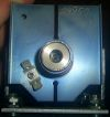
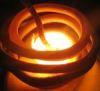
Ok, my circuit is now up and running. Im using 74HC14 schmitt trigger and discrete component gate driver and GDT. I had some phasing problems earlier (either igbts or freewheeling diodes got really hot!) but solved this by changing some component values in feedback circuit. Tank capacitor, so far, is just MMC of 14 x 220nF/1000V plessey KP-series polypropylene foil caps. It stays cool enough at this powerlevel, about 800watts. Work coil gets so hot that watercooling is required for higher power levels. I took some pictures of the system: http://www.elisanet.fi/tonskulus/ih/hothot.jpg http://www.elisanet.fi/tonskulus/ih/ssih_5.jpg
Maybe this helps for designing voltage feedback but I think its not worth that. Current feedback seems to be just fine as we can see from kim ladhas induction heater.. :)
Registered Member #30
Joined: Fri Feb 03 2006, 10:52AM
Location: Glasgow, Scotland
Posts: 6706
Hi guys,
First of all, in order to have real power flow through an inductor, the voltages at its two ends must differ in phase. The phase angle determines the real power flow, and when it's 90 degrees, you have as much real power flow as you're going to get.
Since we want the maximum real power flow, then, we want a feedback system that drives the inverter 90 degrees out of phase to the tank capacitor voltage.
Since the tank capacitor current leads the voltage by 90 degrees (this is always true for a capacitor) it's therefore suitable for a feedback signal. With the inverter locked to this, its output voltage will lead the tank voltage by 90', which is what's needed.
The work coil current is not quite the same as the tank capacitor current (it differs by the current injected from the inverter) but it seems to be close enough, since that's how Karim's circuit worked. Sensing the tank voltage and adding a 90' phase lead will work too.
Richie updated his induction heating page with a much more complete explanation than this.
This site is powered by e107, which is released under the GNU GPL License. All work on this site, except where otherwise noted, is licensed under a Creative Commons Attribution-ShareAlike 2.5 License. By submitting any information to this site, you agree that anything submitted will be so licensed. Please read our Disclaimer and Policies page for information on your rights and responsibilities regarding this site.


 OMG Induction Heater