If you need assistance, please send an email to forum at 4hv dot org. To ensure your email is not marked as spam, please include the phrase "4hv help" in the subject line. You can also find assistance via IRC, at irc.shadowworld.net, room #hvcomm.
Support 4hv.org!
Donate:
4hv.org is hosted on a dedicated server. Unfortunately, this server costs and we rely on the help of site members to keep 4hv.org running. Please consider donating. We will place your name on the thanks list and you'll be helping to keep 4hv.org alive and free for everyone. Members whose names appear in red bold have donated recently. Green bold denotes those who have recently donated to keep the server carbon neutral.
Special Thanks To:
Aaron Holmes
Aaron Wheeler
Adam Horden
Alan Scrimgeour
Andre
Andrew Haynes
Anonymous000
asabase
Austin Weil
barney
Barry
Bert Hickman
Bill Kukowski
Blitzorn
Brandon Paradelas
Bruce Bowling
BubeeMike
Byong Park
Cesiumsponge
Chris F.
Chris Hooper
Corey Worthington
Derek Woodroffe
Dalus
Dan Strother
Daniel Davis
Daniel Uhrenholt
datasheetarchive
Dave Billington
Dave Marshall
David F.
Dennis Rogers
drelectrix
Dr. John Gudenas
Dr. Spark
E.TexasTesla
eastvoltresearch
Eirik Taylor
Erik Dyakov
Erlend^SE
Finn Hammer
Firebug24k
GalliumMan
Gary Peterson
George Slade
GhostNull
Gordon Mcknight
Graham Armitage
Grant
GreySoul
Henry H
IamSmooth
In memory of Leo Powning
Jacob Cash
James Howells
James Pawson
Jeff Greenfield
Jeff Thomas
Jesse Frost
Jim Mitchell
jlr134
Joe Mastroianni
John Forcina
John Oberg
John Willcutt
Jon Newcomb
klugesmith
Leslie Wright
Lutz Hoffman
Mads Barnkob
Martin King
Mats Karlsson
Matt Gibson
Matthew Guidry
mbd
Michael D'Angelo
Mikkel
mileswaldron
mister_rf
Neil Foster
Nick de Smith
Nick Soroka
nicklenorp
Nik
Norman Stanley
Patrick Coleman
Paul Brodie
Paul Jordan
Paul Montgomery
Ped
Peter Krogen
Peter Terren
PhilGood
Richard Feldman
Robert Bush
Royce Bailey
Scott Fusare
Scott Newman
smiffy
Stella
Steven Busic
Steve Conner
Steve Jones
Steve Ward
Sulaiman
Thomas Coyle
Thomas A. Wallace
Thomas W
Timo
Torch
Ulf Jonsson
vasil
Vaxian
vladi mazzilli
wastehl
Weston
William Kim
William N.
William Stehl
Wesley Venis
The aforementioned have contributed financially to the continuing triumph of 4hv.org. They are deserving of my most heartfelt thanks.
Registered Member #205
Joined: Sat Feb 18 2006, 11:59AM
Location: Skørping, Denmark
Posts: 741
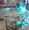
Insight is slowly trickling in, and I now realise, that it was probably wrong to assume up to 2kW into the jacobs ladder we made the other weekend. Point is, the supply delivers constant _current_ into a load, so if this load is a low resistance, which I think a Jacobs ladder arc is, then the current is delivered into a low potential, and therefore the delivered power is also low.
Anyone know the resistance of a jacob ladder arc?
This weekend, we would like to test the supply under power, and we would like to do so into a resistive load. Since we are expecting something in the vicinity of 15-20kW a water resitor comes to mind. A big barrell with salt water and copper electrodes would allow power measurements to be done with temperature rise as the calibration.
But which resistance will mirror the condition of the supply topping up, into a capacitor with 8kV on it?
Able to deliver 4 amps into the load, at a maximum voltage of 8kV, my shot at it is, that the resistor must be not over R=E/I 8000/4=2k. A little lower, really, to keep the load from rising to a voltage over the reach of the supply.
Registered Member #135
Joined: Sat Feb 11 2006, 12:06AM
Location: Anywhere is fine
Posts: 1735
Take some time to do a short circuit and open circuit test on the transformer, then go to the 4hv wiki under electronics and do the transformer analysis. That will give you the extracted elements of the transformer so you can model your problem.
You can find the impedance of the arc from the reflected load on the transformer. Essentially its short circuit at this point so you need to know the equivalent series secondary resistance at this point, but the transformer calculations will help with that.
Registered Member #146
Joined: Sun Feb 12 2006, 04:21AM
Location: Austin Tx
Posts: 1055
Finn, i think your 2k ohm load is the correct value (or at least pretty close) for doing a high power measurement. Keep in mind that this is more stressful than charging a cap, since when you charge a cap the average output power is 1/2 the peak output power when topping off the cap.
As to the jacobs ladder, why not just measure the voltage across the arc? I think it was in the few kV range for me (maybe 2kV).
Registered Member #30
Joined: Fri Feb 03 2006, 10:52AM
Location: Glasgow, Scotland
Posts: 6706
I always wondered about the resistance of a Jacobs ladder. The maximum power transfer theorem says that you should be able to stretch an arc until it's pulling as much power as your supply can give. When it hits the maximum power point, it becomes unstable and goes out. That's what I believe anyway.
Registered Member #146
Joined: Sun Feb 12 2006, 04:21AM
Location: Austin Tx
Posts: 1055
Steve,
That is what i have measured in the past, but the voltage required to sustain longer growing sparks seems to go up with the square of the arc length (this is purely "by eye" type of measurement). In anycase, the voltage drop across the arc climbs steeply just before it breaks. It may present a load thats not too far off from charging a cap.
Registered Member #125
Joined: Fri Feb 10 2006, 01:52PM
Location: Aalborg, Denmark
Posts: 155
Hi Finn.
I have to admit that I think a Jacobs’s ladder is the way to go with our measurements at the moment. But let’s see what weekend brings…
After some hard days with a lot of overtime at my place of work, I managed to calculate a bit more on how many Jules/sec we can deliver with our CCPS as it is now.
Last time we had a Jacob’s ladder on the supply, we had 400Vdc on the bridge. And with the transformers in parallel, we has 136nF in the tank and a Fo about 92kHz. That gives about 4000 J/sec, but if we get the supply on three phase and 560Vdc in the bridge, we should get up to 7800 J/sec… That’s almost twice the energy!!!
We need more C or a higher Fo
I can’t prove that my calculations are correct, because my differential probe and my other probes are at your place
Registered Member #205
Joined: Sat Feb 18 2006, 11:59AM
Location: Skørping, Denmark
Posts: 741
All,
Today, scoping across the IGBT`s suggested that we`d probably better make us a low inductance bus:
Not that it solved our problems, because the whole thing still rings like the liberty bell: TEK TDS2014, Metratek MX9003 diff probe, stock probe on low side gate.
(Yellow trace is voltage across a low side IGBT, blue is gate.)
We read up on RCD snubbers, and placed 1 across the buss between the lytics and the first IGBT. The snubber consists of a 150nF CD942 cap, an IXYS DSEI 60-06A fast diode and a 1.5ohms resistor. This brought os to this situation:
We then placed 2 more snubbers on the bus: (The one to the left is the midle one, the 3rd is off the picture to the left.)
This resulted in this ringing waveform:
These shots are at really low voltages, we forgot to record the voltage, but below 50V.
When we turn the voltage up higher, the overshoot begins to climb up to over 50%, which is worrying, because it will correspond to more than 900V at 560V on the bus.
What?s left to do? Transorbs? Can we calculate the power in these overshots, so that we can also get an idea of how many tranzorbs we need?
Registered Member #205
Joined: Sat Feb 18 2006, 11:59AM
Location: Skørping, Denmark
Posts: 741
All,
If you will all have me excused for double posting, but I think everybody interested in H-bridge design should see this.
As you all know, the gate waveform is regularly displayed with great pride, "the squarer the better" seems to be the rule of the day.
But what about the voltage across swiching devices? We have just seen what ringing it can lead to.
Here are the waveforms showing Current in green, Voltage in blue and gate waveform (yellow), with a 22ohm gate resistor
Nice and calm, and the gate driver is happy, gate resistor is hot (2W) even the main IGBT`s are swallower.
Here is a shot at 250nS to show the calm voltage frontedge at 150V bus,
So with the new gate resistors in situ, the low inductance buss and the snubbers really came to play in harmony. Looks like we are ready to ramp the voltage up to max, now. Not today, though. There is an open house arrangement at the regional electricity plant, won`t miss that!
Registered Member #30
Joined: Fri Feb 03 2006, 10:52AM
Location: Glasgow, Scotland
Posts: 6706
Hi Finn & Daniel,
As far as I know, you are right. The answer to gate drive is not always "As fast as you can". You have to experiment to find out what is right for your system. I have built some (much smaller) DC-DC converters, and I spent a day fiddling with gate resistors and resistor-diode networks until I found the values that made the MOSFETs run coolest.
I'm also playing with those white Semikron IGBTs, and I've also noticed some fairly serious ringing on the bus even at low DC bus voltages. Maybe they are really fast
This site is powered by e107, which is released under the GNU GPL License. All work on this site, except where otherwise noted, is licensed under a Creative Commons Attribution-ShareAlike 2.5 License. By submitting any information to this site, you agree that anything submitted will be so licensed. Please read our Disclaimer and Policies page for information on your rights and responsibilities regarding this site.


 CCPS (Capacitor Charging Power Supply)