If you need assistance, please send an email to forum at 4hv dot org. To ensure your email is not marked as spam, please include the phrase "4hv help" in the subject line. You can also find assistance via IRC, at irc.shadowworld.net, room #hvcomm.
Support 4hv.org!
Donate:
4hv.org is hosted on a dedicated server. Unfortunately, this server costs and we rely on the help of site members to keep 4hv.org running. Please consider donating. We will place your name on the thanks list and you'll be helping to keep 4hv.org alive and free for everyone. Members whose names appear in red bold have donated recently. Green bold denotes those who have recently donated to keep the server carbon neutral.
Special Thanks To:
Aaron Holmes
Aaron Wheeler
Adam Horden
Alan Scrimgeour
Andre
Andrew Haynes
Anonymous000
asabase
Austin Weil
barney
Barry
Bert Hickman
Bill Kukowski
Blitzorn
Brandon Paradelas
Bruce Bowling
BubeeMike
Byong Park
Cesiumsponge
Chris F.
Chris Hooper
Corey Worthington
Derek Woodroffe
Dalus
Dan Strother
Daniel Davis
Daniel Uhrenholt
datasheetarchive
Dave Billington
Dave Marshall
David F.
Dennis Rogers
drelectrix
Dr. John Gudenas
Dr. Spark
E.TexasTesla
eastvoltresearch
Eirik Taylor
Erik Dyakov
Erlend^SE
Finn Hammer
Firebug24k
GalliumMan
Gary Peterson
George Slade
GhostNull
Gordon Mcknight
Graham Armitage
Grant
GreySoul
Henry H
IamSmooth
In memory of Leo Powning
Jacob Cash
James Howells
James Pawson
Jeff Greenfield
Jeff Thomas
Jesse Frost
Jim Mitchell
jlr134
Joe Mastroianni
John Forcina
John Oberg
John Willcutt
Jon Newcomb
klugesmith
Leslie Wright
Lutz Hoffman
Mads Barnkob
Martin King
Mats Karlsson
Matt Gibson
Matthew Guidry
mbd
Michael D'Angelo
Mikkel
mileswaldron
mister_rf
Neil Foster
Nick de Smith
Nick Soroka
nicklenorp
Nik
Norman Stanley
Patrick Coleman
Paul Brodie
Paul Jordan
Paul Montgomery
Ped
Peter Krogen
Peter Terren
PhilGood
Richard Feldman
Robert Bush
Royce Bailey
Scott Fusare
Scott Newman
smiffy
Stella
Steven Busic
Steve Conner
Steve Jones
Steve Ward
Sulaiman
Thomas Coyle
Thomas A. Wallace
Thomas W
Timo
Torch
Ulf Jonsson
vasil
Vaxian
vladi mazzilli
wastehl
Weston
William Kim
William N.
William Stehl
Wesley Venis
The aforementioned have contributed financially to the continuing triumph of 4hv.org. They are deserving of my most heartfelt thanks.
Registered Member #543
Joined: Tue Feb 20 2007, 04:26PM
Location: UK
Posts: 4992
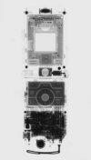
Charging Electrode and Double Box Details
The solder spot is the through-hole termination of the bias input lead.
I used the same standoff arrangements used for the collector plate.
I will divide the electronics box into decoupled compartments so electrons can't start making their own unofficial and unapproved voyages around the circuit.
Registered Member #162
Joined: Mon Feb 13 2006, 10:25AM
Location: United Kingdom
Posts: 3140
I've been following this project with some interest, had a thought, at the ,5 keV range I think that the wavelength of x-ray photons will be of the same order as the atomic spacing of many solids (or am I way out?) which means solids may act as bandpass filters etc?
Registered Member #543
Joined: Tue Feb 20 2007, 04:26PM
Location: UK
Posts: 4992
Sulaiman wrote ...
I've been following this project with some interest, had a thought, at the ,5 keV range I think that the wavelength of x-ray photons will be of the same order as the atomic spacing of many solids (or am I way out?) which means solids may act as bandpass filters etc?
If we first consider the case of visible light, diffraction occurs in a diffraction grating when the spaces between the lines are of the same order as the wavelength of the arriving light - a few thousand Angstroms.
The interatomic spaces in crystalline solids are conveniently of the same order as x-ray wavelengths, so the rays can be diffracted by the repeating patterns of atoms, a fact from which the huge field of x-ray diffraction has evolved since its discovery by Laue in 1912 - a hundred years ago.
A crystalline solid can disperse x-rays according to wavelength (Bragg's Law), just as as a diffraction grating can disperse white light into the colours of the rainbow. This makes it possible to select a particular wavelength, a process used in monochromators to produce (ideally) x-rays of a single wavelength.
None of this is peculiar to the ultra-soft, and I am wondering if you are thinking either of the famous x-ray 'water window' - 280 to 530 eV - which is at the heart of x-ray microscopy of biological specimens, or of the strange and marvellous world of x-ray optics with its multi-layer mirrors and lenses formed from exotic materials.
This project thread is very much about learning as I go along, so perhaps I'll be able to give you a much better answer later on. There's always hope!
Reluctantly, I turned back to the resistors of prodigious value, which it turns out are also of prodigious cost if you want a human-friendly wire-ended one. Like £50 each!
This left me with only 0805 size chip resistors of which I found I had ten that had apparently cost me £1.72 each - still a ludicrous price for something the size of tea leaf. Looking at them in their packaging tape, I wasn't surprised I'd forgotten I had them. No one but a dalek could actually like them.
Anyway, I stuck two strips of copper tape onto a piece of PTFE about 1mm apart, and put spots of solder onto each of them. Using tweezers, I then set a chip resistor as a bridge between the two foil strips, and applied a 15W soldering iron.
Registered Member #1134
Joined: Tue Nov 20 2007, 04:39PM
Location: Bonnie Scotland
Posts: 351
Rather you than me!
How do you intend to protect that tiny resistor from surface leakage, or any kind of surface contamination? I have always found high value resistors like this, quite a challenge to work with.
Registered Member #543
Joined: Tue Feb 20 2007, 04:26PM
Location: UK
Posts: 4992
plazmatron wrote ...
Rather you than me!
How do you intend to protect that tiny resistor from surface leakage, or any kind of surface contamination? I have always found high value resistors like this, quite a challenge to work with.
As for surface contamination, the resistor will be operating inside a sealed, dessicated box, but I don't find this very reassuring.
I may coat the resistor and its surrounds with clear acrylic nail polish, and then measure its resistance again when the varnish has hardened, to see if it is still usable.
Registered Member #1938
Joined: Sun Jan 25 2009, 12:44PM
Location: Romania
Posts: 699
great design on the ion chamber, and a very interesting project that I hoped for a long time to see happening.
once you get over the high ohmic resistor issues, and get the tiny ion chamber current (well, maybe not so tiny at the x-ray intensity you are going to generate) translated into a measurable voltage, how do you plan to amplify that while keeping noise down?
Registered Member #543
Joined: Tue Feb 20 2007, 04:26PM
Location: UK
Posts: 4992
radhoo wrote ...
great design on the ion chamber, and a very interesting project that I hoped for a long time to see happening.
once you get over the high ohmic resistor issues, and get the tiny ion chamber current (well, maybe not so tiny at the x-ray intensity you are going to generate) translated into a measurable voltage, how do you plan to amplify that while keeping noise down?
already having a suitable Op amp in mind?
I'm working on it right now, Radhu! I've tried several designs so far. At the moment, I'm trying an FET source follower with a constant current BJT in the source lead, to get a gain hopefully >0.99 and ultra-high impedance. Then I will have a two stage amplifier - either OPA177 or OPA200 - because I have some of both. Once I have something that is stable, I will add refinements, one at a time, to see how I can improve it.
Registered Member #543
Joined: Tue Feb 20 2007, 04:26PM
Location: UK
Posts: 4992
Glass stand-off insulators
This is how I make glass stand-off insulators using 4mm glass beads and 6mm self-adhesive copper tape. The glass beads cost 99p (EUR 1.24) per 100.
A 5mm punch cuts copper foil disks just the right size to stick on top of the 4mm glass beads. A block of hard wood placed under the copper foil, and good sharp tap of the hammer, helps to ensure a clean cut. The cut discs go up inside the barrel of the punch, and have to be pushed out in a column like a core bore through sedimenatry rock. A few of them get damaged in the prcoess.
It can be a bit fiddly peeling off the self-adhesive backing, but a scalpel blade will easily lift an edge.
The completed stand-offs are ready to be stuck to the PCB copper ground plane with 5-minute epoxy.
Registered Member #2261
Joined: Mon Aug 03 2009, 01:19AM
Location: London, UK
Posts: 581
Could you direct backscattering electrons away from your Beryllium window by applying to it a suitably large negative bias voltage, reducing the heating effect and thus enabling a thinner window to be used?
This site is powered by e107, which is released under the GNU GPL License. All work on this site, except where otherwise noted, is licensed under a Creative Commons Attribution-ShareAlike 2.5 License. By submitting any information to this site, you agree that anything submitted will be so licensed. Please read our Disclaimer and Policies page for information on your rights and responsibilities regarding this site.


 Life Below 5 keV