If you need assistance, please send an email to forum at 4hv dot org. To ensure your email is not marked as spam, please include the phrase "4hv help" in the subject line. You can also find assistance via IRC, at irc.shadowworld.net, room #hvcomm.
Support 4hv.org!
Donate:
4hv.org is hosted on a dedicated server. Unfortunately, this server costs and we rely on the help of site members to keep 4hv.org running. Please consider donating. We will place your name on the thanks list and you'll be helping to keep 4hv.org alive and free for everyone. Members whose names appear in red bold have donated recently. Green bold denotes those who have recently donated to keep the server carbon neutral.
Special Thanks To:
Aaron Holmes
Aaron Wheeler
Adam Horden
Alan Scrimgeour
Andre
Andrew Haynes
Anonymous000
asabase
Austin Weil
barney
Barry
Bert Hickman
Bill Kukowski
Blitzorn
Brandon Paradelas
Bruce Bowling
BubeeMike
Byong Park
Cesiumsponge
Chris F.
Chris Hooper
Corey Worthington
Derek Woodroffe
Dalus
Dan Strother
Daniel Davis
Daniel Uhrenholt
datasheetarchive
Dave Billington
Dave Marshall
David F.
Dennis Rogers
drelectrix
Dr. John Gudenas
Dr. Spark
E.TexasTesla
eastvoltresearch
Eirik Taylor
Erik Dyakov
Erlend^SE
Finn Hammer
Firebug24k
GalliumMan
Gary Peterson
George Slade
GhostNull
Gordon Mcknight
Graham Armitage
Grant
GreySoul
Henry H
IamSmooth
In memory of Leo Powning
Jacob Cash
James Howells
James Pawson
Jeff Greenfield
Jeff Thomas
Jesse Frost
Jim Mitchell
jlr134
Joe Mastroianni
John Forcina
John Oberg
John Willcutt
Jon Newcomb
klugesmith
Leslie Wright
Lutz Hoffman
Mads Barnkob
Martin King
Mats Karlsson
Matt Gibson
Matthew Guidry
mbd
Michael D'Angelo
Mikkel
mileswaldron
mister_rf
Neil Foster
Nick de Smith
Nick Soroka
nicklenorp
Nik
Norman Stanley
Patrick Coleman
Paul Brodie
Paul Jordan
Paul Montgomery
Ped
Peter Krogen
Peter Terren
PhilGood
Richard Feldman
Robert Bush
Royce Bailey
Scott Fusare
Scott Newman
smiffy
Stella
Steven Busic
Steve Conner
Steve Jones
Steve Ward
Sulaiman
Thomas Coyle
Thomas A. Wallace
Thomas W
Timo
Torch
Ulf Jonsson
vasil
Vaxian
vladi mazzilli
wastehl
Weston
William Kim
William N.
William Stehl
Wesley Venis
The aforementioned have contributed financially to the continuing triumph of 4hv.org. They are deserving of my most heartfelt thanks.
Registered Member #2431
Joined: Tue Oct 13 2009, 09:47PM
Location: Chico, CA. USA
Posts: 5639
Turkey9 wrote ...
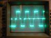
Wow that's really cool! It will be great to actually get wave forms from all the transformers we to get HV. If that wave form came from tapping the 9V to the primary, what are all those little pulses before the big one? Noise from the mechanical contact? I'd expect them not to be as uniform as they are.
yes its so cool! and fun too! but i think the small sines are the primary oscillating unitil the magnetic air gap collapses, then causing the main pulse to appear at the secondary.
Turkey9 wrote ...
I only ran the sweep in the sim to 10 Mhz, but at that point the attenuation had dropped a couple dB. Up at that frequency the ratio will decrease so keep that in mind when making accurate measurements.
can you post a pic? CHIT! 10MHz ii was hoping for at least 50MHz! can you extend the graph alittle to 20-30MHz?
Registered Member #1451
Joined: Wed Apr 23 2008, 03:48AM
Location: Boulder, Co
Posts: 661
Sure. Here are two, one to 50Mhz and one to 100Mhz. This is where you really see the non-linearity. The solid line is the attenuation, the dotted line is the phase shift.
Registered Member #2431
Joined: Tue Oct 13 2009, 09:47PM
Location: Chico, CA. USA
Posts: 5639
Turkey9 wrote ...
Sure. Here are two, one to 50Mhz and one to 100Mhz. This is where you really see the non-linearity. The solid line is the attenuation, the dotted line is the phase shift.
I must have made the caps to big....? Thats not at all what i expected. though ive had bogus and wrong simulations befoer...
what was the circuit you programmed into pspice? can you post it?
Ive also simulated this one and verified it performance with MULTIsim 10...
Registered Member #1451
Joined: Wed Apr 23 2008, 03:48AM
Location: Boulder, Co
Posts: 661
Well looks like I made a mistake in the simulation. I forgot that in Spice M is the same as m so the plots I posted before were with 125 miliohm resistors! Oops!
I redid the sim with the right values and got a very different plot. There is still something interesting, however. The plot below is to 10kHz and stays completely flat all the way past 10GHz. The low frequency is interesting though.
Registered Member #30
Joined: Fri Feb 03 2006, 10:52AM
Location: Glasgow, Scotland
Posts: 6706
Hey Patrick,
I think it's because of the 6.4nF cap in your anti-reflection device or whatever it is. As far as the capacitive division ratio is concerned, it appears in parallel with C4.
If you didn't take that into account, there's twice as much capacitance in the lower arm of the thing as you thought. The capacitive division ratio works out about 6dB lower than the resistive one, and the time constant of the error is a few hundred Hz (6.4nF and 75k) That matches the error shown in the LTSpice sim.
The simulations won't show the true behaviour at really high frequencies, because the simple model of a 125M resistor with a 4pF cap across it starts to break down: the big HV resistors actually have distributed capacitance to their surroundings. That's what all the other trimmers in the Tektronix HV probe are for.
That said, I'm sure your probe will be a valuable tool once you get the little bugs ironed out.
Registered Member #2431
Joined: Tue Oct 13 2009, 09:47PM
Location: Chico, CA. USA
Posts: 5639
Dr. Watt The Fork wrote ...
Hey Patrick,
I think it's because of the 6.4nF cap in your anti-reflection device or whatever it is. As far as the capacitive division ratio is concerned, it appears in parallel with C4.
If you didn't take that into account, there's twice as much capacitance in the lower arm of the thing as you thought. The capacitive division ratio works out about 6dB lower than the resistive one, and the time constant of the error is a few hundred Hz (6.4nF and 75k) That matches the error shown in the LTSpice sim.
The simulations won't show the true behaviour at really high frequencies, because the simple model of a 125M resistor with a 4pF cap across it starts to break down: the big HV resistors actually have distributed capacitance to their surroundings. That's what all the other trimmers in the Tektronix HV probe are for.
That said, I'm sure your probe will be a valuable tool once you get the little bugs ironed out.
I wasnt expecting to use this device past 100MHz or so....
Registered Member #2431
Joined: Tue Oct 13 2009, 09:47PM
Location: Chico, CA. USA
Posts: 5639
new data, progress made, i realize how to get the graph of both phase and magnitude substantially flat.
The math!
Bode plots, on the left is magnitude, on the right is phase.
Categorized data from the above bode plots.
Critical points from the above graphs and data, from DC to 130MHz and above to + infinity.... (note that at 311Hz the phase peaks at 2.2 degrees.)
a double blunder on my part, the 37.5k resistor is right, the 75k resistor is wrong! oops!
Given the recurrence of 311Hz, i believe the resistive and capacitive components converge at this freq, 311Hz is where teh phase shift peaks at 2.2 degrees. 311Hz is where the division ratio is closest to 10,000:1 (or -80dB).
The resistive elements below 311Hz show 375Mohms of impedance. the capaciteve elements show significantly higher impedance (than 375Mohms) below 311Hz therefore, i conclude that between DC -311Hz the capcitors contribute little or no current. Thus the resistors are making the real measurement.
However, nearing 311Hz the capacitors begin to contribute more current and begin to equal the resistive current. it is at this point that the cap dividers (1:5,000 div(sub C)) current begins to equal the resistive dividers (1:10,000 div(sub R)) current.
Above 311Hz the capcitive impedance falls far below 375Mohms, so whatever current is provided via the 10,000:1 resistive divider is overwelmed and pulled towards the capacitive divider's voltage due to the C's lower impedance, and higher current contribution. Therefore, i believe that significantly above the 311Hz mark, the capacitors are making the real measurement.
This makes a happy finding (perhaps). It might be possible to build a capacitive voltage divider that functions from about 500Hz to 1GHz with no or fewer supporting components in the probe circuit, and still have good response, at the expense of DC and low freq measurement.
This site is powered by e107, which is released under the GNU GPL License. All work on this site, except where otherwise noted, is licensed under a Creative Commons Attribution-ShareAlike 2.5 License. By submitting any information to this site, you agree that anything submitted will be so licensed. Please read our Disclaimer and Policies page for information on your rights and responsibilities regarding this site.


 High voltage probe for O-scope, 2 of 2, ( FABRICATION ).