If you need assistance, please send an email to forum at 4hv dot org. To ensure your email is not marked as spam, please include the phrase "4hv help" in the subject line. You can also find assistance via IRC, at irc.shadowworld.net, room #hvcomm.
Support 4hv.org!
Donate:
4hv.org is hosted on a dedicated server. Unfortunately, this server costs and we rely on the help of site members to keep 4hv.org running. Please consider donating. We will place your name on the thanks list and you'll be helping to keep 4hv.org alive and free for everyone. Members whose names appear in red bold have donated recently. Green bold denotes those who have recently donated to keep the server carbon neutral.
Special Thanks To:
Aaron Holmes
Aaron Wheeler
Adam Horden
Alan Scrimgeour
Andre
Andrew Haynes
Anonymous000
asabase
Austin Weil
barney
Barry
Bert Hickman
Bill Kukowski
Blitzorn
Brandon Paradelas
Bruce Bowling
BubeeMike
Byong Park
Cesiumsponge
Chris F.
Chris Hooper
Corey Worthington
Derek Woodroffe
Dalus
Dan Strother
Daniel Davis
Daniel Uhrenholt
datasheetarchive
Dave Billington
Dave Marshall
David F.
Dennis Rogers
drelectrix
Dr. John Gudenas
Dr. Spark
E.TexasTesla
eastvoltresearch
Eirik Taylor
Erik Dyakov
Erlend^SE
Finn Hammer
Firebug24k
GalliumMan
Gary Peterson
George Slade
GhostNull
Gordon Mcknight
Graham Armitage
Grant
GreySoul
Henry H
IamSmooth
In memory of Leo Powning
Jacob Cash
James Howells
James Pawson
Jeff Greenfield
Jeff Thomas
Jesse Frost
Jim Mitchell
jlr134
Joe Mastroianni
John Forcina
John Oberg
John Willcutt
Jon Newcomb
klugesmith
Leslie Wright
Lutz Hoffman
Mads Barnkob
Martin King
Mats Karlsson
Matt Gibson
Matthew Guidry
mbd
Michael D'Angelo
Mikkel
mileswaldron
mister_rf
Neil Foster
Nick de Smith
Nick Soroka
nicklenorp
Nik
Norman Stanley
Patrick Coleman
Paul Brodie
Paul Jordan
Paul Montgomery
Ped
Peter Krogen
Peter Terren
PhilGood
Richard Feldman
Robert Bush
Royce Bailey
Scott Fusare
Scott Newman
smiffy
Stella
Steven Busic
Steve Conner
Steve Jones
Steve Ward
Sulaiman
Thomas Coyle
Thomas A. Wallace
Thomas W
Timo
Torch
Ulf Jonsson
vasil
Vaxian
vladi mazzilli
wastehl
Weston
William Kim
William N.
William Stehl
Wesley Venis
The aforementioned have contributed financially to the continuing triumph of 4hv.org. They are deserving of my most heartfelt thanks.
Registered Member #2511
Joined: Mon Dec 07 2009, 02:46AM
Location:
Posts: 36
I have just run a few tests using the induction heater inverter and the now nearly-finished tank circuit. The tank consists of 6 turns of 8mm copper pipe and has an inductance of 0.53 uH; the capacitor bank is 2.51uF/440Vac. Resonant frequency is 138 kHz.
So far I've turned input power up to about 500W, using a variac to increase input voltage. The problem:
Everything works fine as long as the workpiece is not yet glowing red hot. Input power is small (I'm using a conservative 200W, as the coupling transformer is still underdimensioned), inverter current about 2A, cooling fins of the FETs stay cold as ice. No detectable temperature rise, neither in the coupling transformer (I'm using a bigger, better one than the single toroid in the image above - that one got pretty hot at 200W, despite being ferrite (of unknown properties, most likely for RFI suppression, so far from ideal))
But when the workpiece reaches a dull-red temperature, inverter current begins to rise rapidly - seems almost like a runaway process. (edit: just noticed that tank voltage rises dramatically too, as well as input power). In the first instance it happened, input power soared to slightly over 1kW over about 10-15 seconds and inverter current went up to over 30A. Both FETs (IRFP460) blew. Have since replaced them, but every time the workpiece reaches glowing temperatures, inverter current rises. I now re-adjust the variac to a lower voltage when that happens, to keep inverter current at about 2A and input power at about 200W.
I know that when a workpiece reaches the Curie temperature, hysteresis losses disappear and we're only left with eddy current losses. However, I had never expected the difference to be *so* dramatic - from 2A to over 30A of current.... Seems like the inverter is nearly running unloaded when the workpiece becomes red hot, to cause such a dramatic rise in current?
My question: is this normal, expected behaviour? Especially the degree of current rise. What can I do to keep input power reasonable? Add more turns to the transformer? Permanently lower input voltage? (which lowers output power, so means it takes longer to reach a certain temperature). Add more load?
What I want is the workpiece to get hotter than 'red hot' - white hot. But it seems the inverter starts to protest and absorb all the power in the zone between a red hot and white hot workpiece?
Note that at the moment I'm still running a test-setup, not using the PLL controller board. I first want to get a feeling for how it all behaves, before I control the inverter automatically. The inverter is now powered via a variac, and input signal generated with a function generator, whilst monitoring tank voltage on the scope, and input power with a 'kill-a-watt' meter. The PLL controller board has an inverter over-current safety, which shuts off the inverter when inverter current rises above a set limit. So the inverter is protected, but it's not really controlling inverter current.
Unrelated: one other thing that was very noticeable was that when frequency is just below, or exactly at resonance, there are some nasty spikes on the tank voltage waveshape. Adjusting frequency to slightly above resonance makes that disappear and produces a nice clean sine waveshape, though at a slightly smaller amplitude than when at 'full' resonance (I estimate about 3-4% less tank voltage). This seems to confirm what Richie Burnett writes on his website, that ideally you want the inverter to run a tad above resonant frequency for clean switching.
Registered Member #190
Joined: Fri Feb 17 2006, 12:00AM
Location:
Posts: 1567
When you get the steel glowing hot the current will start to go up. The resonant frequency will also change, so you will need to make sure you stay above the frequency. Monitor the inverter voltage and the inverter current, making sure they are in phase, or at least have the current lagging.
Registered Member #1232
Joined: Wed Jan 16 2008, 10:53PM
Location: Doon tha Toon!
Posts: 881
When iron goes through it's Curie temperature it looses its magnetic properties. Therefore one of the loss factors involved in the induction heating process (the hysteresis loss component) drops out of the equation.
This decrease in energy loss raises the Q of a series resonant tank circuit. And as a result of the higher Q the current drawn from the inverter goes up.
As you spotted the inverter will operate quite happily when tuned to any frequency higher than the natural frequency of the series resonant tank circuit, except real power throughput diminishes away from resonance. (Only on the low-frequency side of resonance does the tank look capacitive and forced reverse-recovery of the FWDs causes those nasty spikes and EMI that gets EVERYWHERE!)
The easiest way to keep the inverter current under control when the tank Q rises, is to tune the inverter to a slightly higher frequency. The high Q of the tank circuit means that the phase angle of the load current changes quickly for a small change in f, so you won't need to detune much for the active power contribution to decrease back to something more reasonable. (The slight lagging PF of the load current is actually a good thing as it helps to commutate the devices in the inverter during the switch's dead-times.)
Registered Member #2511
Joined: Mon Dec 07 2009, 02:46AM
Location:
Posts: 36
Thanks for the responses, all.
As I'm still driving the inverter manually (using a variac and function generator), I'm beginning to learn how it behaves. Indeed, when the workpiece starts to glow inverter current rises, and so does input power and tank voltage. When it starts to rise I back off the variac to keep input power constant at about 600W (600W is what it normally draws, at 230V, with the present amount of turns on the coupling transformer, but it's capable of 1000W continuous without anything overheating).
I'm amazed how quickly it heats a workpiece to red hot, even at limited power; just tried a 12mm rod of steel - after 50-80 seconds it's red hot. The amount of energy it takes is only about 0.01 kWh, or 10 Wh.
Am still running it without watercooling, but even at 500-600W for more than a minute, the working coil gets very hot. Part of this is no doubt because of radiated heat from the glowing workpiece. I will add watercooling to the machine too, wich is needed, even at that relatively small (for an induction heater) power. My intention is to adjust it, when finished, to a maximum power of 750W (the inverter cooling fins remain cold, btw, as do the 3 powdered-iron toroids (yellow/white)).
I had already finished building the PLL controller (Hernán González's design, with modifications) but it doesn't seem to lock onto the tank resonant frequency. I'm still debugging the board but having good hopes of getting it working; I'm now suspecting the LM393s introduce too much phaseshift between their inputs and outputs, at 138 kHz, and one of them is oscillating at about 40 kHz. And there are some other things to test for. When using this PLL, it will automatically detune the VCO to a higher frequency as tank voltage increases beyond the set value, so that means no more manually backing the variac off.
Here's the obligatory picture of a glowing piece of steel:
In other news.... I managed to get the Kemppi welding inverter working again. The IGBT brick was defect. Checked the gate drive but that was fine (no spikes >20V that might damage the IGBT), so I ordered a similar IGBT brick (which was cheaper than I had initially feared) and the machine works again. Very nice machine, with a smooth and stable arc. And can't beat the cost.
Registered Member #2511
Joined: Mon Dec 07 2009, 02:46AM
Location:
Posts: 36
Succes at last!
After messing about with the induction heater's control board for 3 evenings and one full day, it seems to finally be working properly now. After many hours messing with comparators that preferred to oscillate rather than compare, comparators that saw up to -15V input whereas they can't take more than -0.3V, leakage currents due to solder flux that messed everything up, phase-errors introduced by too long transit times in NAND-inverters, etc.etc, and a reversed diode that prevented the loop filter's control signal from ever reaching the voltage controlled oscillator , most major bugs seem to have been ironed out finally.
So now it's possible to run the induction heater 'automatically', i.e. without needing to tune for resonance manually, or adjusting the variac to prevent magic smoke escaping: the PLL now tunes for exact resonance and the tank over-voltage protection kicks in when it gets above about 60V, protecting the inverter from too high loads and running unloaded. And the turn-on sequence doesn't matter, i.e whether you first turn on the PLL and then the inverter, or otherwise - nothing blows. That's good.
To satisfy the visual aspect, here's a picture of the workbench. Somewhere in that mess there's a working induction heater.
To the left the tank circuit, with workpiece in it (hard to see, but glowing red-hot as 850W of RF is being pushed into it). It's still working off the variac, but more as a precaution to quickly reduce voltage if needed - it's now continuously working on 230Vac.
The scope above shows the waveshape - perfectly locked onto the resonant frequency (which varies, depending on the size of the load, i.e. workpiece, and temperature it has). Amplitude is about 60Vac, which means that about 130A of current circulates in the tank circuit. And that shows: the 8mm copper pipes get *hot*, the workcoil gets scorching hot, and the capacitors get warm (about 50 deg. C) after a while. Not surprizing, as each has to handle about 7.5A at 140kHz... So watercooling is most definitely not a luxury, not even at this relatively low power level of 850W, not if you want to run it for more than a few minutes at a time. Have pushed output power up to 1000W without problems, but don't want to get much higher because of the capacitorbank that's becoming the limiting factor
The analog meter to the above-right of the scope shows the tank voltage as measured by the controller, about 60V. Nice to have an analog display of tank voltage, and see how it rises as the workpiece starts to glow, after which over-voltage limit kicks in and reduces power to a safe 150W.
The yellow/white powdered iron toroids transfer the energy from the inverter to the tank circuit. Primary contains 14 turns of wire (still have to optimize this part; less turns may be a possibility, without the inverter protesting). Toroids stay cool, to my surprize, so will use these in the final construction too.
To the right of the tank circuit, the inverter - a half bridge with 2 MTW14N50E 's (I ran out of IRFP460s.... though all blew while I was still driving it manually - under automatic control, nothing unexpected happens, due to the inverter current limit and tank voltage limits). The cooling fins of the FETs stay cool, don't get above 35C even after extended running at 850W, so that's good too.
To the right of the inverter is the PLL control circuit. Contains its own 15V regulated power supply. A 4046 takes care of the PLL/VCO business. Various comparators do the signal processing and provide some security features, to protect against tank overvoltage and inverter overcurrent. When an error is triggered, power gets reduced to a safe level by detuning the VCO to a higher frequency (thus limiting power throughput) and lighting a LED (and in the final build, buzzing a buzzer). After resetting the error (preferrably after setting the power-control potmeter a tad lower), it starts locking and heating at full (set) power again.
The DMM at the top-right indicates the VCO input voltage, which determines the VCO's frequency. Should be somewhere between 1-14V, preferably being at the mid-point, 7V, but at 6V it's close enough for the moment, as there's still plenty of headroom to regulate below and above the resonant frequency.
To the right of the PLL, the infamous Oztules PC PSU, which provides all the power for the control board and gatedriver, at 24V.
And this is what all that fancy electronics does....
Looks much the same as the image of a glowing steel rod a few posts before, only this time it does it all automatically - just press the start button, and press stop when finished.
Tried out whether I could get a workpiece hot enough for brazing - alas, didn't work. It's getting close, but not there quite yet. 850W isn't much power either. But I don't want to push this machine much higher, we'll save that for the follow-up project (which will use a ready-made 7.2kVA full-bridge inverter; as I can't draw more than 3700W from single-phase grid anyway, that seems sturdy enough).
That's it - long writeup, but not nearly as long as it took to get it into its present working state. Next task is to debug the last errors (esp. inverter current error latching circuit) and then start building it into its cabinet, an old PC mini-tower.
Many thanks go to forum member Hernán González, to whom much of the control circuitry is attributed. I added some improvements and modifications myself (and weeded out a few errors in the design too), NeonJohn for the idea of the series topology and generally excellent website, and Iamsmooth for his induction heater tutorial. Especially the explanations on the working of a PLL were valuable to me.
And of course all the forum members for their input, ideas and comments - Thanks!
Registered Member #2511
Joined: Mon Dec 07 2009, 02:46AM
Location:
Posts: 36
One thing I've noticed when running the induction heater under automatic control is that, when it detunes to a frequency higher than resonance, I get some dirt on the tank voltage sine - see scope images.
Picture below shows a zoomed-in region, of the valley of the sine:
The frequency of the oscillations are about 43MHz, and have a maximum amplitude of about 20 Vpk-pk (at 160Vpk-pk fundamental signal at 136 kHz)
While I was initially driving the induction heater inverter manually, using a function generator, I noticed that when my drive frequency was below resonance, the 'dirty stuff' was just after the peaks (i.e. to the right of the hills and valleys of the sine). Driving it below resonant frequency is supposedly bad due to forced commutation of the FETs.
But now is the first time I see this dirt at a frequency above resonance (when detuning the inverter for less power, i.e. increasing the VCO control voltage, to reduce power throughput).
The questions:
- is this dirt on the tank voltage normal? Is it acceptable, at its present amplitude? - is there anything that should be done about it? - if so, what could be done about it (apart from tuning to exact resonance)
Or maybe I worry too much, as driving the IH at a frequency above resonance is supposed to be safe....
Registered Member #190
Joined: Fri Feb 17 2006, 12:00AM
Location:
Posts: 1567
The regular intervals of your "dirt" suggests this is during switching. Maybe your deadtime between switching is too long? I am not knowledgeable enough to tell. How do you control your switch timing?
You said it locks perfectly which is great. What is the frequency range of your PLL? What happens if you put something other than a bolt inside like a chunk of copper or a small steel nut? I found with my topology it locks onto resonance, but is usually a little off and needs to get perfectly tuned by adjusting a pot to my integrator feedback loop.
As soon I have learned enough I am going to build an 8kw unit using a microprocessor to lock onto resonance using a PLL/VCO. I am hoping to have resolution down to 50hz increments for scaning a frequency range of 50-150khz.
Registered Member #30
Joined: Fri Feb 03 2006, 10:52AM
Location: Glasgow, Scotland
Posts: 6706
The dirt is just switching transients. Above resonance, the FETs don't switch at zero current any more, so they start to make these little bursts of RF as they suddenly interrupt this non-zero current. They get into the ground system and appear just about everywhere. (And make you fail your EMC test if you're not careful!)
It's not a problem. If it looked like this -that might be a problem :)
This site is powered by e107, which is released under the GNU GPL License. All work on this site, except where otherwise noted, is licensed under a Creative Commons Attribution-ShareAlike 2.5 License. By submitting any information to this site, you agree that anything submitted will be so licensed. Please read our Disclaimer and Policies page for information on your rights and responsibilities regarding this site.


 induction heater project - feedback on inverter.
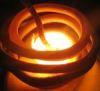


 , most major bugs seem to have been ironed out finally.


