If you need assistance, please send an email to forum at 4hv dot org. To ensure your email is not marked as spam, please include the phrase "4hv help" in the subject line. You can also find assistance via IRC, at irc.shadowworld.net, room #hvcomm.
Support 4hv.org!
Donate:
4hv.org is hosted on a dedicated server. Unfortunately, this server costs and we rely on the help of site members to keep 4hv.org running. Please consider donating. We will place your name on the thanks list and you'll be helping to keep 4hv.org alive and free for everyone. Members whose names appear in red bold have donated recently. Green bold denotes those who have recently donated to keep the server carbon neutral.
Special Thanks To:
Aaron Holmes
Aaron Wheeler
Adam Horden
Alan Scrimgeour
Andre
Andrew Haynes
Anonymous000
asabase
Austin Weil
barney
Barry
Bert Hickman
Bill Kukowski
Blitzorn
Brandon Paradelas
Bruce Bowling
BubeeMike
Byong Park
Cesiumsponge
Chris F.
Chris Hooper
Corey Worthington
Derek Woodroffe
Dalus
Dan Strother
Daniel Davis
Daniel Uhrenholt
datasheetarchive
Dave Billington
Dave Marshall
David F.
Dennis Rogers
drelectrix
Dr. John Gudenas
Dr. Spark
E.TexasTesla
eastvoltresearch
Eirik Taylor
Erik Dyakov
Erlend^SE
Finn Hammer
Firebug24k
GalliumMan
Gary Peterson
George Slade
GhostNull
Gordon Mcknight
Graham Armitage
Grant
GreySoul
Henry H
IamSmooth
In memory of Leo Powning
Jacob Cash
James Howells
James Pawson
Jeff Greenfield
Jeff Thomas
Jesse Frost
Jim Mitchell
jlr134
Joe Mastroianni
John Forcina
John Oberg
John Willcutt
Jon Newcomb
klugesmith
Leslie Wright
Lutz Hoffman
Mads Barnkob
Martin King
Mats Karlsson
Matt Gibson
Matthew Guidry
mbd
Michael D'Angelo
Mikkel
mileswaldron
mister_rf
Neil Foster
Nick de Smith
Nick Soroka
nicklenorp
Nik
Norman Stanley
Patrick Coleman
Paul Brodie
Paul Jordan
Paul Montgomery
Ped
Peter Krogen
Peter Terren
PhilGood
Richard Feldman
Robert Bush
Royce Bailey
Scott Fusare
Scott Newman
smiffy
Stella
Steven Busic
Steve Conner
Steve Jones
Steve Ward
Sulaiman
Thomas Coyle
Thomas A. Wallace
Thomas W
Timo
Torch
Ulf Jonsson
vasil
Vaxian
vladi mazzilli
wastehl
Weston
William Kim
William N.
William Stehl
Wesley Venis
The aforementioned have contributed financially to the continuing triumph of 4hv.org. They are deserving of my most heartfelt thanks.
Registered Member #1819
Joined: Thu Nov 20 2008, 04:05PM
Location:
Posts: 137
Very nice work. I never thought of using copper pipes as bus bars ; looks like I'll be using that for my coilgun.
The arrangement of your bus bars is good; in fact, that is the recommended arrangement for equal current distribution among all of the capacitors, as specified in a capacitor application note.
Keep up the good work! I can't wait to see how well this will perform.
Registered Member #1062
Joined: Tue Oct 16 2007, 02:01AM
Location:
Posts: 1529
You make the diodes look so much better from when i mounted them... On those diodes, tighten them as much as you can, the toothed washers are more effective than.
Registered Member #30
Joined: Fri Feb 03 2006, 10:52AM
Location: Glasgow, Scotland
Posts: 6706
Am I the only one who can't see what earthly good diodes in series with the load will do? By the physics of RLC circuits, the current doesn't reverse until after the capacitor voltage has reversed and got as far negative as it's going to. So your capacitors and anti-parallel diodes are already blown by this point.
Registered Member #1837
Joined: Tue Dec 02 2008, 02:20PM
Location: NYC
Posts: 65
Just another point of concern is using pipe for bus bars. Copper pipe is made from recycled copper. The recycling process leaves way to much impurity to make new electrical conductors. This may show up when you have large amps moving. I'm not saying it's not worth a shot, just be careful.
Registered Member #1497
Joined: Thu May 22 2008, 05:24AM
Location: Toronto, Ontario, Canada
Posts: 801
Well there are SCR's on both the +ve and -ve side of the capacitors, and the diodes increase the total standoff voltage. Once the capacitors discharge through a inductive load, the inductor causes the voltage reversal. If there are that many diodes to block voltage reversal (2 scrs in series and 1 'big' diode), should there be little reverse biasing of the capacitors?
Registered Member #1819
Joined: Thu Nov 20 2008, 04:05PM
Location:
Posts: 137
aonomus wrote ...
Well there are SCR's on both the +ve and -ve side of the capacitors, and the diodes increase the total standoff voltage. Once the capacitors discharge through a inductive load, the inductor causes the voltage reversal. If there are that many diodes to block voltage reversal (2 scrs in series and 1 'big' diode), should there be little reverse biasing of the capacitors?
The simulation said it would work at least....
Steve McConner made an important point. Inductors, when charged with energy, are current sources. They will increase the voltage across themselves until there is an available current path (theoretically to infinity). This means the inductive load will automatically increase its voltage until it is enough to blow thorugh all of your SCRs and diodes. Then it will go to your capacitors and... the rest is self-explanatory (a.k.a. expensive). Instead, you should put the diodes in anti-parallel with the inductive load and place a resistor in series with the diode so that the voltage spike resulting from inductor peak current does not exceed the total reverse breakdown of your SCRs (V = I * R).
Registered Member #1497
Joined: Thu May 22 2008, 05:24AM
Location: Toronto, Ontario, Canada
Posts: 801
So I finally got some traction on this project again... yesterday I had the capacitor bank charger/control system panel laser-cut from a really heavy duty ABS case (1/4" thick, IP66 rated, it was not fun to cut). The capacitor bank charger was based off of Uzzors ZVS driver with a few tweaks mainly for voltage control and voltage reference. the only remaining building for the charger would be wiring up the relays to control the charger.
On the capacitor bank side, I have reconfigured the SCRs in parallel, but I still have to mount the diodes and then solder all the bus bars together.
Note: the slight amount of burning was due to the laser being set too high, but a little soap/water will clean that char right off.
Registered Member #1497
Joined: Thu May 22 2008, 05:24AM
Location: Toronto, Ontario, Canada
Posts: 801
So over the last 2 days I've worked to get this project finished finally. All the bus bars are soldered, connections tightened, discharge load mounted and connected to SCR.
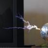
I had some fun doing low power tests, right up until I exploded some wire at 25% power.
Videos: Testing at low power for can crushing and ring launching: Slow motion of the last test that left my ears ringing:
This site is powered by e107, which is released under the GNU GPL License. All work on this site, except where otherwise noted, is licensed under a Creative Commons Attribution-ShareAlike 2.5 License. By submitting any information to this site, you agree that anything submitted will be so licensed. Please read our Disclaimer and Policies page for information on your rights and responsibilities regarding this site.


 2.5kJ Capacitor Bank (Complete, finally!)
 ; looks like I'll be using that for my coilgun.