If you need assistance, please send an email to forum at 4hv dot org. To ensure your email is not marked as spam, please include the phrase "4hv help" in the subject line. You can also find assistance via IRC, at irc.shadowworld.net, room #hvcomm.
Support 4hv.org!
Donate:
4hv.org is hosted on a dedicated server. Unfortunately, this server costs and we rely on the help of site members to keep 4hv.org running. Please consider donating. We will place your name on the thanks list and you'll be helping to keep 4hv.org alive and free for everyone. Members whose names appear in red bold have donated recently. Green bold denotes those who have recently donated to keep the server carbon neutral.
Special Thanks To:
Aaron Holmes
Aaron Wheeler
Adam Horden
Alan Scrimgeour
Andre
Andrew Haynes
Anonymous000
asabase
Austin Weil
barney
Barry
Bert Hickman
Bill Kukowski
Blitzorn
Brandon Paradelas
Bruce Bowling
BubeeMike
Byong Park
Cesiumsponge
Chris F.
Chris Hooper
Corey Worthington
Derek Woodroffe
Dalus
Dan Strother
Daniel Davis
Daniel Uhrenholt
datasheetarchive
Dave Billington
Dave Marshall
David F.
Dennis Rogers
drelectrix
Dr. John Gudenas
Dr. Spark
E.TexasTesla
eastvoltresearch
Eirik Taylor
Erik Dyakov
Erlend^SE
Finn Hammer
Firebug24k
GalliumMan
Gary Peterson
George Slade
GhostNull
Gordon Mcknight
Graham Armitage
Grant
GreySoul
Henry H
IamSmooth
In memory of Leo Powning
Jacob Cash
James Howells
James Pawson
Jeff Greenfield
Jeff Thomas
Jesse Frost
Jim Mitchell
jlr134
Joe Mastroianni
John Forcina
John Oberg
John Willcutt
Jon Newcomb
klugesmith
Leslie Wright
Lutz Hoffman
Mads Barnkob
Martin King
Mats Karlsson
Matt Gibson
Matthew Guidry
mbd
Michael D'Angelo
Mikkel
mileswaldron
mister_rf
Neil Foster
Nick de Smith
Nick Soroka
nicklenorp
Nik
Norman Stanley
Patrick Coleman
Paul Brodie
Paul Jordan
Paul Montgomery
Ped
Peter Krogen
Peter Terren
PhilGood
Richard Feldman
Robert Bush
Royce Bailey
Scott Fusare
Scott Newman
smiffy
Stella
Steven Busic
Steve Conner
Steve Jones
Steve Ward
Sulaiman
Thomas Coyle
Thomas A. Wallace
Thomas W
Timo
Torch
Ulf Jonsson
vasil
Vaxian
vladi mazzilli
wastehl
Weston
William Kim
William N.
William Stehl
Wesley Venis
The aforementioned have contributed financially to the continuing triumph of 4hv.org. They are deserving of my most heartfelt thanks.
Registered Member #1107
Joined: Thu Nov 08 2007, 10:09PM
Location:
Posts: 792
eh... probably but less chemicals = less cost and seeing that it is a use materials that are lying around budget it is not necessary. Also here is a pic of the electrode setup.
Registered Member #477
Joined: Tue Jun 20 2006, 11:51PM
Location: Seattle, WA
Posts: 546
Hey, groovy! Lookin' good. Once it seems to be working, you might do what I *didn't* do, and try to mount some PVC over the top half of the assembly to make it safer. Cut a slot down the side of some larger-diameter PVC so that the handle can slide up and down freely, but so that you don't have all that exposed copper.
...or just conjure your own design that doesn't require having anything extend above the water besides the control handle. I have one in mind that I should draw up and see if it makes any sense. Basically, the idea would be that the conductors would be fixed in place at the bottom of the can much as they are in the above design, but would be held together at the top only by the control sleeve, which in addition to the long section in the design above, would have another "mini sleeve" that would go around the second pipe just to hold them together. Don't know if I did a good job explaining that. As usual, a picture is worth a zillion (or so) words.
Registered Member #1628
Joined: Wed Aug 06 2008, 08:48PM
Location: Huntsville, AL USA
Posts: 95
Basically, the idea would be that the conductors would be fixed in place at the bottom of the can much as they are in the above design, but would be held together at the top only by the control sleeve, which in addition to the long section in the design above, would have another "mini sleeve" that would go around the second pipe just to hold them together. Don't know if I did a good job explaining that. As usual, a picture is worth a zillion (or so) words.
I would like to see a picture. I have a pig project going if I can ever get it off the ground.
Registered Member #477
Joined: Tue Jun 20 2006, 11:51PM
Location: Seattle, WA
Posts: 546
Bamacoiler wrote ...
I would like to see a picture. I have a pig project going if I can ever get it off the ground.
Sure. I'll try and draw something tonight.
Actually "mini" isn't even required; just imagine two sleeves, one on each pipe, but fastened together so that you're exposing each pipe simultaneously. The only advantage of doing this versus a single sleeve like above is that the sleeves hold the pipes in parallel, so you needn't bolt the pipes together at the top. Then you just need to make sure you can't lift the sleeves above the tops of the pipes, or else they'll do bad things (like fall into each other and cause a short circuit ).
In this design, you'd be forced (although that's not necessarily bad) to connect the wires to the bottoms of the pipes instead of the tops.
Cheers, Aaron, N7OE
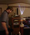
EDIT: Ok, first, I found a really crappy video frame showing my old setup. Looks an awful lot like the diagram above, I expect!
Next, here's a diagram showing my proposed "2.0" design. This drawing is far from complete. Explanation below.
In this new version, you see that there are two sleeves bolted together at the top. The only real purpose of two would be to keep the copper pipes in parallel (pretend the copper pipes only run up as high as the surface of the water in this diagram; they are not connected at the top like in the first diagram posted earlier). To keep the whole assembly from tipping over, you'd have to get a little tricky. You'll see in the photo of my v1.0 water ballast that the assembly is held in place at the top by a crossbeam of PVC that's attached to the rim of the can and to the non-sleeved copper pipe. In the v2.0 design, you'd have to run the whole assembly through some kind of collar at the top of the can. It would be tempting to simply use the garbage can's lid with a hole cut in the middle, but more holes might be a good idea if you did that just to make sure the gasses are vented efficiently. The bottom of the assembly would be mounted in the same way as the first (in mine, I just made a cross shape with PVC and fastened it to the bottom of the assembly). In either design, the wires could be connected to the bottom. I used the top in mine only because it was convenient and I was mainly fiddling.
The other trick that needs to be worked out in v2.0 is keeping the operator from raising the control handle too high, which would set the copper pipes loose! A neat way to do that would probaby be to add some protrusion (e.g., bolts) to the sides of one of the control sleeves so that it would stop when it contacted the bottom of the collar that's holding the assembly in the center at the top of the can. I'm sure people can think of other ways, too.
Obviously, the v1.0 design is easier to build. v2.0 seems a little safer, but put a cover over the top half of the assmebly in v1.0 and it's probably a wash.
Hope this discussion is remaining interesting I feel like I might be babbling a bit...
Registered Member #1107
Joined: Thu Nov 08 2007, 10:09PM
Location:
Posts: 792
Well here is a update on my work. I flattened out some copper pipe and connected it to elbows like rp181 suggested and it made a nice bussbar connector. All the hookup wire is 4awg battery cable i got it for free thanks to my oldest cousin who is a bmw mechanic. Tomorrow i will probably make the base and put everything together for testing on Monday. I am really happy with how it is coming along and i hope it will work well. Here are some pic's of what i got done.
Registered Member #477
Joined: Tue Jun 20 2006, 11:51PM
Location: Seattle, WA
Posts: 546
Coolness, I can't wait to see it go! Don't be surprised if you need to add quite a bit of baking soda to get the conductivity of the water up where you want it. I forget how much I had to add, I just remember being surprised!
Don't let those spacers fall out! I can't quite tell how they're held in place, so maybe you're ok; I'm just sayin'!
Registered Member #1107
Joined: Thu Nov 08 2007, 10:09PM
Location:
Posts: 792
Myke wrote ...
J. Aaron Holmes wrote ...
Don't let those spacers fall out! I can't quite tell how they're held in place, so maybe you're ok; I'm just sayin'!
Looks like there is some black plastic between the pipes. Maybe it's ABS?
Looks cool so far. I can't wait to see a video.
You were close Actually it is just some tinted 1/4" plexi i had laying around. Then as you can see it is clamped down by some clamps i made out of pvc pipe. Before i test it i will probably glue the spacers in just to be safe.
This site is powered by e107, which is released under the GNU GPL License. All work on this site, except where otherwise noted, is licensed under a Creative Commons Attribution-ShareAlike 2.5 License. By submitting any information to this site, you agree that anything submitted will be so licensed. Please read our Disclaimer and Policies page for information on your rights and responsibilities regarding this site.


 saturable reactor (now water ballast)


 ).
).

 I feel like I might be babbling a bit...


 Actually it is just some tinted 1/4" plexi i had laying around. Then as you can see it is clamped down by some clamps i made out of pvc pipe. Before i test it i will probably glue the spacers in just to be safe.
