If you need assistance, please send an email to forum at 4hv dot org. To ensure your email is not marked as spam, please include the phrase "4hv help" in the subject line. You can also find assistance via IRC, at irc.shadowworld.net, room #hvcomm.
Support 4hv.org!
Donate:
4hv.org is hosted on a dedicated server. Unfortunately, this server costs and we rely on the help of site members to keep 4hv.org running. Please consider donating. We will place your name on the thanks list and you'll be helping to keep 4hv.org alive and free for everyone. Members whose names appear in red bold have donated recently. Green bold denotes those who have recently donated to keep the server carbon neutral.
Special Thanks To:
Aaron Holmes
Aaron Wheeler
Adam Horden
Alan Scrimgeour
Andre
Andrew Haynes
Anonymous000
asabase
Austin Weil
barney
Barry
Bert Hickman
Bill Kukowski
Blitzorn
Brandon Paradelas
Bruce Bowling
BubeeMike
Byong Park
Cesiumsponge
Chris F.
Chris Hooper
Corey Worthington
Derek Woodroffe
Dalus
Dan Strother
Daniel Davis
Daniel Uhrenholt
datasheetarchive
Dave Billington
Dave Marshall
David F.
Dennis Rogers
drelectrix
Dr. John Gudenas
Dr. Spark
E.TexasTesla
eastvoltresearch
Eirik Taylor
Erik Dyakov
Erlend^SE
Finn Hammer
Firebug24k
GalliumMan
Gary Peterson
George Slade
GhostNull
Gordon Mcknight
Graham Armitage
Grant
GreySoul
Henry H
IamSmooth
In memory of Leo Powning
Jacob Cash
James Howells
James Pawson
Jeff Greenfield
Jeff Thomas
Jesse Frost
Jim Mitchell
jlr134
Joe Mastroianni
John Forcina
John Oberg
John Willcutt
Jon Newcomb
klugesmith
Leslie Wright
Lutz Hoffman
Mads Barnkob
Martin King
Mats Karlsson
Matt Gibson
Matthew Guidry
mbd
Michael D'Angelo
Mikkel
mileswaldron
mister_rf
Neil Foster
Nick de Smith
Nick Soroka
nicklenorp
Nik
Norman Stanley
Patrick Coleman
Paul Brodie
Paul Jordan
Paul Montgomery
Ped
Peter Krogen
Peter Terren
PhilGood
Richard Feldman
Robert Bush
Royce Bailey
Scott Fusare
Scott Newman
smiffy
Stella
Steven Busic
Steve Conner
Steve Jones
Steve Ward
Sulaiman
Thomas Coyle
Thomas A. Wallace
Thomas W
Timo
Torch
Ulf Jonsson
vasil
Vaxian
vladi mazzilli
wastehl
Weston
William Kim
William N.
William Stehl
Wesley Venis
The aforementioned have contributed financially to the continuing triumph of 4hv.org. They are deserving of my most heartfelt thanks.
Registered Member #125
Joined: Fri Feb 10 2006, 01:52PM
Location: Aalborg, Denmark
Posts: 155
Hi Finn.
I think it’s time for me to say a few things about our project .
I like your gate driver, and after an afternoon in your workshop this weekend, with blown optocouplers and a headache, I am pretty satisfied with the results. Too bad we didn’t get a chance to test it on our CCPS…
About the transformer, I must agree with you!
I think we should do it the “Ward†way, and place the primary under the secondary winding, and make an extra series inductor to adjust from. If you agree with me I’ll order two of these from RS (Part number) 213-4470, and use the cores we have in parallel.
Registered Member #30
Joined: Fri Feb 03 2006, 10:52AM
Location: Glasgow, Scotland
Posts: 6706
Yay, this is looking great
About the matching inductor, I think Steve used an air cored one. You don't need very much inductance if you're transferring a lot of power, as you figured out. If you use ferrite, you'll need a large air gap to avoid saturation. You certainly wouldn't want to use that RS part you mentioned without any airgap!
Registered Member #89
Joined: Thu Feb 09 2006, 02:40PM
Location: Zadar, Croatia
Posts: 3145
Hi Steve, Daniel, Finn
You need Only few tens of uH at most, and I think material #26 (yellow-white toroids) would be more than fine for you at these currents. With rough calculation I think even the size from PC power supply would suffice.
About the matching inductor, I think Steve used an air cored one. You don't need very much inductance if you're transferring a lot of power, as you figured out. If you use ferrite, you'll need a large air gap to avoid saturation. You certainly wouldn't want to use that RS part you mentioned without any airgap!
Steve, I don't think airgap actually does any good with inductors like these.
Inductance will reduce proportionally with permeability and we really get nothing except need to wind more copper onto the core. (OK, with rod cores, this may save some ferrite from other side).
Material #26 has saturation B of about afaik 1T while #77 ferrite is 0.45T max according to CWS table. Most use ferrite to maybe 0.3T.
In any wa ferrite core would need to be larger and more expensive for this application.
The great thing about air cored coil is it's absolute stability, but it is a bad thing when we need 15amps continuously through it at 50kHz.
Registered Member #30
Joined: Fri Feb 03 2006, 10:52AM
Location: Glasgow, Scotland
Posts: 6706
Are you sure about that? The peak current in the resonant circuit should only be something like 3 times what it would be in a hard-switched converter. That gives a loaded Q of 3 even at full output voltage.
For 15kW on a 560V DC bus, a hard-switched converter would run about 30A, so you should have something like 90A peak current. Say 100 since you have an IGBT brick handy
Try designing your circuit such that the leakage inductance and capacitor end up with a surge impedance of (560/100) ohms and a resonant frequency of say 100kHz, or whatever frequency you decide gives acceptable losses. (Switching losses should be low because you have zero current at turn-on and turn-off, so you might be able to aim higher in frequency than the IGBT datasheet would suggest. However, you have to bear in mind that if the loaded Q is too low, you will lose your zero-current turn-off at higher output voltages. This is a trade-off.)
Registered Member #125
Joined: Fri Feb 10 2006, 01:52PM
Location: Aalborg, Denmark
Posts: 155
Hi Steve,
I’m almost sure that my calculations are correct… The I peak of 248A is in the resonance circuit, and looking at other peoples work with high power CCPS`s, their I peak resonant current is in the 100-1100A area..
Registered Member #89
Joined: Thu Feb 09 2006, 02:40PM
Location: Zadar, Croatia
Posts: 3145
For 15kW on a 560V DC bus, a hard-switched converter would run about 30A, so you should have something like 90A peak current. Say 100 since you have an IGBT brick handy
Right now he has impedance of 2,23 ohms which is quite way far. As far as I understood it, he's limited by total charge he can push through the cap in one cycle, and making the cap big enough makes characteristic Z way too low. If I understood anything of this?
Steve: You didn't answer the thing about cores.. I actually wonder if I'm right or wrong
Registered Member #30
Joined: Fri Feb 03 2006, 10:52AM
Location: Glasgow, Scotland
Posts: 6706
Re the thing about cores, it's a known fact that the energy storage before saturation is proportional to the size of the airgap. An ungapped ferrite core can store practically no energy. I've not investigated it myself, but I hear that gapped ferrite isn't nearly so good as iron powder toroids.
Daniel: It always seemed to me that the CCPS tank circuit impedance was a tradeoff between conduction losses caused by higher peak currents, and switching losses caused by it falling out of ZCS at certain output voltages due to not having enough peak current. I think Marco Denicolai explored this with PSpice in a lot of detail. Running at a lower frequency than f0/2 might help too.
Registered Member #205
Joined: Sat Feb 18 2006, 11:59AM
Location: Skørping, Denmark
Posts: 741
Thanks for the input,
These numbers are for a single transformer, topping out at 4kV.
At present: Z= 25.44, 92kHz 68nF, 44uH, Ipeak, start 25A Ipeak, end 50A , 4kW (1uF to 4kV, 8J, in 2mS)
So we we missed the goal by 50%.....
With a Z of 5, 100kHz, 315nF, 8.04uH, Ipeak, start 100A Ipeak, end 200A (1uF to 4kV, 8J, in 0.4mS = 20kW)
Yes, I get the picture.
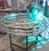
The transformer probably has to leave the cabinet, and sure is up for a rewind. The winding window will get *optimally filled* by pie shaped secondary windings.
Waw, this sure is fun stuff.
I feel kind of tempted to skip the negative gate drive on the IGBT`s and adopt Terry`s source follower supplies, from his DRSSTC, but that may have to wait untill the next iteration.
This site is powered by e107, which is released under the GNU GPL License. All work on this site, except where otherwise noted, is licensed under a Creative Commons Attribution-ShareAlike 2.5 License. By submitting any information to this site, you agree that anything submitted will be so licensed. Please read our Disclaimer and Policies page for information on your rights and responsibilities regarding this site.


 CCPS (Capacitor Charging Power Supply)