If you need assistance, please send an email to forum at 4hv dot org. To ensure your email is not marked as spam, please include the phrase "4hv help" in the subject line. You can also find assistance via IRC, at irc.shadowworld.net, room #hvcomm.
Support 4hv.org!
Donate:
4hv.org is hosted on a dedicated server. Unfortunately, this server costs and we rely on the help of site members to keep 4hv.org running. Please consider donating. We will place your name on the thanks list and you'll be helping to keep 4hv.org alive and free for everyone. Members whose names appear in red bold have donated recently. Green bold denotes those who have recently donated to keep the server carbon neutral.
Special Thanks To:
Aaron Holmes
Aaron Wheeler
Adam Horden
Alan Scrimgeour
Andre
Andrew Haynes
Anonymous000
asabase
Austin Weil
barney
Barry
Bert Hickman
Bill Kukowski
Blitzorn
Brandon Paradelas
Bruce Bowling
BubeeMike
Byong Park
Cesiumsponge
Chris F.
Chris Hooper
Corey Worthington
Derek Woodroffe
Dalus
Dan Strother
Daniel Davis
Daniel Uhrenholt
datasheetarchive
Dave Billington
Dave Marshall
David F.
Dennis Rogers
drelectrix
Dr. John Gudenas
Dr. Spark
E.TexasTesla
eastvoltresearch
Eirik Taylor
Erik Dyakov
Erlend^SE
Finn Hammer
Firebug24k
GalliumMan
Gary Peterson
George Slade
GhostNull
Gordon Mcknight
Graham Armitage
Grant
GreySoul
Henry H
IamSmooth
In memory of Leo Powning
Jacob Cash
James Howells
James Pawson
Jeff Greenfield
Jeff Thomas
Jesse Frost
Jim Mitchell
jlr134
Joe Mastroianni
John Forcina
John Oberg
John Willcutt
Jon Newcomb
klugesmith
Leslie Wright
Lutz Hoffman
Mads Barnkob
Martin King
Mats Karlsson
Matt Gibson
Matthew Guidry
mbd
Michael D'Angelo
Mikkel
mileswaldron
mister_rf
Neil Foster
Nick de Smith
Nick Soroka
nicklenorp
Nik
Norman Stanley
Patrick Coleman
Paul Brodie
Paul Jordan
Paul Montgomery
Ped
Peter Krogen
Peter Terren
PhilGood
Richard Feldman
Robert Bush
Royce Bailey
Scott Fusare
Scott Newman
smiffy
Stella
Steven Busic
Steve Conner
Steve Jones
Steve Ward
Sulaiman
Thomas Coyle
Thomas A. Wallace
Thomas W
Timo
Torch
Ulf Jonsson
vasil
Vaxian
vladi mazzilli
wastehl
Weston
William Kim
William N.
William Stehl
Wesley Venis
The aforementioned have contributed financially to the continuing triumph of 4hv.org. They are deserving of my most heartfelt thanks.
Registered Member #10
Joined: Thu Feb 02 2006, 09:45AM
Location: Bunbury, Australia
Posts: 1424
Terry Fritz wrote ...
... I enhanced and commented it here: You can see every known leader phenomena in it!!!! Here is a reference from Bazelyan/Raizer. It looks like the leader tip stalls a bit probably as that cycle reverses and cuts off the power. The next cycle reheats it and eventually it goes onward and breifly stalls again....
I don't think these are leader tips and my interpretation is a little different. What you have labelled as the leader tip on the left looks to me like a simple change in direction for the spark. In the two dimensions we see it in there is a sudden change in direction downwards. This will overlap the streamers and make that area bright. If the area is much brighter than expected (as it appears to be visually) then this is due to a third dimensional effect, ie the spark goes in or out of the plane of view for a distance which will relate to the perceived brightness. The second leader tip that you indicate on the right occurs where a streamer branches. Again there is streamer overlap. In both cases the streamer channel continues although all the 4 or 5 channels may be "stepped" so it looks like one or two were stopped. The diagrams from Bazelyan/Raizer, while not well labelled with time axes, indicate much faster events analysing what happens within the first strike that I just see as a single event.
Terry Fritz wrote ...
Interestingly there is no ring down on the main arc
That is a hit or miss thing. Often the power is totally removed from the streamer so the arc is dead right there. Models predict that based on stuff that still needs to be studied. It is probably fairly consistant (if it will occur or not) with a given coil setup.
The presence or absence of ring down is seen in different sparks in the same photo in the (second photo in my last post) so it is not just a coil setup issue. I would have thought that it is hard to remove all energy in one cycle from a resonant circuit without some ringing.
Pic #1 below shows variation in the intensity of each ring up spark channel. Pic #2 below shows tthe two most central sparks of similar intensity. Can you tell which is a streamer and which is a spark? (Sparks ring down and streamers ring up) On the full photo the streamer fades but the spark doesn't. Pic #3 Shows many streamer channels
Zoom - To fit the image nicely to the picture. Does not seem to affect light gathering. Optical zoom only as opposed to stupid software zoom.
Shutter speed - Does not matter much. Long enough that you get a good chance of "catching" an arc. 1/10 and 1/20 sec does well here.
Background sensor noise - Don't worry about trying to fix noise by subtraction of a dark frame or anything. Oddly, that seems to hurt more than help. If your camera does this automatically, I think it should be turned off. The key is a sensitive low noise sensor to begin with!!
Aperture - As big as possible!! You need to gather as much light as you possibly can at all costs!!
Len's - If you have a choice, one that gathers the most light.
ISO - As high as possible!!! 1,000,000 would be nice!!! Mine only goes to 400 at that is barely enough. One of those cameras that can be forced up to 16,000 whether it is good or not would be nice. You really need this one!!! As Dan and other's say, getting data out of the camera in a deep RAW format would really help here too. The cool stuff is just barely above the noise level in my case.
Distance - As close as possible just to gather more light!!
Speed - My four rotating mirror block is running at about 5000 RPM. 2000 - 6000 RPM would be fine. I think slower is a bit better since more light hits the sensor pixels that way, but you want it to be fast enough to separate the pulses.
The room should be very dark to eliminate stray light.
Flash - Be sure to turn that **^*&%* thing off!!! There you are in the dark fiddling with the camera and blammo!! Almost knocked me over.
Remote shutter is ultra nice!! If the camera can take pictures automatically at say every second that would be very nice too. But you can do the shutter button too.
White Balance - I used daylight, but it is turning out black and white mostly in my case as I super pump up the brightness and contrast.
EV - Set it up high to brighten the picture as much as possible, but it had no effect in my camera's manual mode.
Reset - Set the camera so it does not loose all the settings when the power is turned off
Focus - Manual. I just measured it and set the camera to that distance. This could be tricky, but I did not have much trouble with it.
Background - Black felt works fine.
I took about 200 pictures today. Mostly figuring out by trial and error what is good. Rechargeable batteries are good too but you don't use the flash so the battery drain is pretty low. I did keep the LCD screen on all the time.
At 5000 RPM you can just glue the mirror to the little motor shaft or whatever. No need for a fancy machined block. No need for four mirrors, just one would do fine with a longer shutter speed to catch a good arc on one of the rotations.
The stray light paths near the mirror should be blocked and all the surfaces should be painted black to eliminate stray light reflections.
So it is pretty easy. I did have to carefully increase brightness and contrast with software to see air streamers. They are barely above the noise level. However, power arcs are very easy to see. I had to go back to all the black frames and lighten them so see if there were air streamers. Power arcs show up right away.
I put a 40.5MB zip file with a lot of pictures here:
At the bottom of the page select "free". It makes you wait about 2 minutes to read the ads and then a download screen comes up. Enter the funny letters in the robot trap box and save the file. It is just a typical zip file filled with all the JPG images from the last "lucky run". Some are plain and some have been enhanced. Some of those pictures are just black too... The four read streaks to the left or the calibration LED flashing at 100kHz. Each mirror makes it's own streak depending on the fine alignment of the mirror. If the pulses are blurred out, it is because that mirror scanned twice while the shutter was open.
I "think" time increases from bottom to top. Hard to say since the camera is upside down, inverted, twisted, and the motor turns in some direction... "Hard to say for sure" #;-)) I will try to modify the calibrator so it gradually goes out to point in the right direction. The calibrator is not really needed but it does prove the speed and all.
Thanks to Peter for figuring all this out!!! I think you are even working on an improvement )
I don't know what the pictures "mean" yet since Just taking the pictures is the deal right now.
Cheers,
Terry
To follow up...
I modified the calibrator for 1uS on time pulses at 100kHz but with a diode and cap so it has a "tail" to point in the direction of time.
So time so increasing from the bottom, toward to top in my pictures.
This is most interesting ))
I took one good frame and enhanced it with comments (1.7MB to preserve all the detail):
You can see each ring up pulse now!!!!!!!!
The first pulse is very weak but visible.
The second pulse 5uS latter is stronger and has a significant downward branch but its upward branch almost goes 1/2 the distance.
The third pulse almost gets there and clearly stimulates streamers off the ground point.
The fourth pulse arcs and completes in a very bright area between the previous leader and the corona off the ground point.
Here is a ScanTesla equivalent:
This coil is highly predictable and the trailing oscillations are due to the leftover energy in the primary circuit. But those oscillations are weak in this case and do not show up at all in the photo.
Registered Member #10
Joined: Thu Feb 02 2006, 09:45AM
Location: Bunbury, Australia
Posts: 1424
Great pics for first light, Terry even if you people do things upside down compared to here in Australia (the time axis is going up). The camera is the limitation here even despite your SISG having brighter sparks. You have a larger field than me which will also reduce the available light. The 100kHz LED works well and fortunately the 4 images don't overlap otherwise you wouldn't see anything. Given your machining tolerances, I guess this is a difference due to epoxy thickness. How long are the sparks? I look forward to closer pics with better detail. I will look at 40M file as well. I have more plans but have the small matter of a day (and part of the night) job.
Registered Member #30
Joined: Fri Feb 03 2006, 10:52AM
Location: Glasgow, Scotland
Posts: 6706
Wow Terry, that's astounding! You actually caught a Tesla coil streamer in the act of growing and striking a target. Does it grow on both the half-cycles of topload voltage, or only one polarity?
The 100kHz LED works well and fortunately the 4 images don't overlap otherwise you wouldn't see anything.
Often you can make out the timing light even if they do overlap. I changed the light for only a 10% duty cycle which should really help that.
Given your machining tolerances, I guess this is a difference due to epoxy thickness. How long are the sparks?
The block was pressed on at 4000 pounds with a hammer "helping out" with some impact. I suspect a bent the 1/8 inch motor shaft a little but I wanted to be sure it did not fall off at 30,000 RPM Of course, that speed is not needed. 2000-6000 RPM does fine where just glueing the mirror right to the motor shaft would be fine. The arc distance is 23 inches.
Steve wrote:
Does it grow on both the half-cycles of topload voltage, or only one polarity?
The timing light is 100kHz and the Fo of the coils is 103kHz. Since the streamer growth pulses are at 5uS, they are clearly both the - and + pulses of the cycle. In this case I can directly compare the pulses to the ScanTesla computer model of this coil here:
I do not know the absolute polarity of the coil this moment though.
Registered Member #146
Joined: Sun Feb 12 2006, 04:21AM
Location: Austin Tx
Posts: 1055
Why not have the strobe light take feedback from the secondary output voltage just like our SSTCs do. That way the strobe can be synched, and you will know which half-cycle you are on in the picture.
One could also use a CT on the secondary base current lead to direct drive the LEDs (Red/Green high-brightness). The base current is 90 degrees off, but it would give the same info. It might get a little odd with ground strikes.
The schematic for my calibrator is here:
This one has the "tails" indicating the direction of increasing time.
But once you know the direction and general time idea, the calibrator serves no function anymore. I am not using it now.
The SISG coil always fires in the same DC top voltage mode and the voltage looks like this:
This is comparable to the model which I now remember I matched for voltage direction:
In the big picture here:
I doubt the first little 50kV nub could have made the first leader shown. So I think the above is all valid.
I am actually using higher scan speeds now. I tried slowing it to make the sparks linger on the pixels longer for more brightness, but that does not help. More spread is what it needs. I also need to cut ambient light way down more. A mirror redesign is in the works. So is a much better camera )
Registered Member #30
Joined: Fri Feb 03 2006, 10:52AM
Location: Glasgow, Scotland
Posts: 6706
Is there any way you could get an oscilloscope screen to appear in your streak photo, showing the instantaneous voltage? I can't imagine how you would create a trace that wasn't smeared because of the phosphor persistence of the scope.
Maybe you could make a LED bargraph showing the instantaneous output voltage, and the motion of the mirror would turn it into a scope trace. I don't know if those LM3914 thingies are fast enough to hook up to an antenna.
Registered Member #10
Joined: Thu Feb 02 2006, 09:45AM
Location: Bunbury, Australia
Posts: 1424
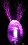
OK here is my fabulous "improvement". It is so simple it only took me 4 or 5 hours and a few blown high power ultrafast diodes and TVS's. In the end I settled for this. Only 4 components, two of which are red LED's. Simply, it reads the polarity of a spark. The led closest to the spark is negative ie the spark from the toroid on the left is a negative leader. They then alternate polarity far further than one can see as a spark. Lots of interesting stuff is going on here now that I have looked at many of then. More in future posts
Guess how I did it. ie what are the two other components.
Is there any way you could get an oscilloscope screen to appear in your streak photo, showing the instantaneous voltage? I can't imagine how you would create a trace that wasn't smeared because of the phosphor persistence of the scope.
The scope could be postitioned in the picture outside the spinning mirror. Probably need another mirror so you can put the scope at a distance so it will be in focus. I guess you would have to run in single shot so 50 images combined would not smear it up. Of course, digital scopes display the data far too late to be useful. There might be some odd way to use the camera hot shoe to trigger the scope on just the right spark too.
Maybe you could make a LED bargraph showing the instantaneous output voltage, and the motion of the mirror would turn it into a scope trace. I don't know if those LM3914 thingies are fast enough to hook up to an antenna.
I made an LED scope thing once with them but I am not sure they can do say 500kHz. It would be easy to test if anyone has a LM3914 around. That data sheet did not say.
TDU said:
Guess how I did it. ie what are the two other components.
Cool!
I will "guess" two LEDs a resistor and a MOV. The strike current might be 2000A for a few nS which will kill most TVSs and such. It really helps to keep the device voltage low so the instant power is lower too. A capacitor might also work if one could guess the right value.
This site is powered by e107, which is released under the GNU GPL License. All work on this site, except where otherwise noted, is licensed under a Creative Commons Attribution-ShareAlike 2.5 License. By submitting any information to this site, you agree that anything submitted will be so licensed. Please read our Disclaimer and Policies page for information on your rights and responsibilities regarding this site.


 High speed Tesla spark photos


 )
)


 You actually caught a Tesla coil streamer in the act of growing and striking a target. Does it grow on both the half-cycles of topload voltage, or only one polarity?
 Of course, that speed is not needed. 2000-6000 RPM does fine where just glueing the mirror right to the motor shaft would be fine. The arc distance is 23 inches.


