If you need assistance, please send an email to forum at 4hv dot org. To ensure your email is not marked as spam, please include the phrase "4hv help" in the subject line. You can also find assistance via IRC, at irc.shadowworld.net, room #hvcomm.
Support 4hv.org!
Donate:
4hv.org is hosted on a dedicated server. Unfortunately, this server costs and we rely on the help of site members to keep 4hv.org running. Please consider donating. We will place your name on the thanks list and you'll be helping to keep 4hv.org alive and free for everyone. Members whose names appear in red bold have donated recently. Green bold denotes those who have recently donated to keep the server carbon neutral.
Special Thanks To:
Aaron Holmes
Aaron Wheeler
Adam Horden
Alan Scrimgeour
Andre
Andrew Haynes
Anonymous000
asabase
Austin Weil
barney
Barry
Bert Hickman
Bill Kukowski
Blitzorn
Brandon Paradelas
Bruce Bowling
BubeeMike
Byong Park
Cesiumsponge
Chris F.
Chris Hooper
Corey Worthington
Derek Woodroffe
Dalus
Dan Strother
Daniel Davis
Daniel Uhrenholt
datasheetarchive
Dave Billington
Dave Marshall
David F.
Dennis Rogers
drelectrix
Dr. John Gudenas
Dr. Spark
E.TexasTesla
eastvoltresearch
Eirik Taylor
Erik Dyakov
Erlend^SE
Finn Hammer
Firebug24k
GalliumMan
Gary Peterson
George Slade
GhostNull
Gordon Mcknight
Graham Armitage
Grant
GreySoul
Henry H
IamSmooth
In memory of Leo Powning
Jacob Cash
James Howells
James Pawson
Jeff Greenfield
Jeff Thomas
Jesse Frost
Jim Mitchell
jlr134
Joe Mastroianni
John Forcina
John Oberg
John Willcutt
Jon Newcomb
klugesmith
Leslie Wright
Lutz Hoffman
Mads Barnkob
Martin King
Mats Karlsson
Matt Gibson
Matthew Guidry
mbd
Michael D'Angelo
Mikkel
mileswaldron
mister_rf
Neil Foster
Nick de Smith
Nick Soroka
nicklenorp
Nik
Norman Stanley
Patrick Coleman
Paul Brodie
Paul Jordan
Paul Montgomery
Ped
Peter Krogen
Peter Terren
PhilGood
Richard Feldman
Robert Bush
Royce Bailey
Scott Fusare
Scott Newman
smiffy
Stella
Steven Busic
Steve Conner
Steve Jones
Steve Ward
Sulaiman
Thomas Coyle
Thomas A. Wallace
Thomas W
Timo
Torch
Ulf Jonsson
vasil
Vaxian
vladi mazzilli
wastehl
Weston
William Kim
William N.
William Stehl
Wesley Venis
The aforementioned have contributed financially to the continuing triumph of 4hv.org. They are deserving of my most heartfelt thanks.
Registered Member #2431
Joined: Tue Oct 13 2009, 09:47PM
Location: Chico, CA. USA
Posts: 5639
Finished!!!!!!!!!!!!!!!!!!!!!!!!!! ( I Hope. )
EDIT: it looks GOOD, real good, so far at low freq (60 Hz) at 6000 Vac RMS... now i really need that callibrator!
EDIT 2: it can resolve on sine waves of 60uS which is about 17kHz, which was way better then the purely resistive dividers ive built in the past...
EDIT 3: it sees all sorts of stuff with an iggy and a 18 V battery... This THING ACTUALLY WORKS !
EDIT 4: I can verify a point proud mary and i pondered, if you disable the X10 button its the normal 10,000:1 ratio, but enable the 10X button and it becomes a 1000:1 ratio! How cool is that!
Testing will begin in a few hours, i have math homework i gotta do now though.
She still needs her permanent tats which ill print out and laminate soon.
Single trimmer for compensation, weeping yet Tektronix p601* users?
Registered Member #2431
Joined: Tue Oct 13 2009, 09:47PM
Location: Chico, CA. USA
Posts: 5639
I gonna try to get this transformer working for some super HV, maybe 30 plus kV....
As, Proud Mary sugggested ive been able to find A 65 volt sub coil, its not intended to be used as a primary but it has the same AWG wire as the orignal primary, and has sbout 0.5 ohms or less.
I dont see any oscillograms of Flybacks here on the forum so ill gather some.
Twisted green wires are for a thermistor at the hot spot. Yellow and black twisted pair is the primary. single black and large red is for secondary HV out. 9v for scale.
OLd variant in oil tank, new mod in fore ground.
EDIT: i have to be careful im getting 2.2 inch HOT sparks between two sharp points. Ill be using a series output resistor to prevent a short lived flyback. I have to admit the internaL primary does seem much better.
Registered Member #2431
Joined: Tue Oct 13 2009, 09:47PM
Location: Chico, CA. USA
Posts: 5639
OOPS! i made a blunder, the lower division resistor should be 75k ohms, not the quoted 37.5k ohms, DUH. i forgot that the both the C and R parrallel dividers are supposed to divide by 5,000:1 then then the compensation and anti reflection components in the cord divide by 2:1, therefore 5,000:1 in series with 2:1 yields a 10,000:1 total ratio.
in the above schematic R4 is shown as 37.5k ohms, but should be 75k ohms. My error.
Registered Member #162
Joined: Mon Feb 13 2006, 10:25AM
Location: United Kingdom
Posts: 3140
Patrick, sorry to comment so late in the project but based on the circuit diagram that you posted the dc attenuation and ac attenuation (or lf and hf if you like) are different, and the bottom arrangement of 75k (or 37k5) feeding a terminated 50 Ohm transmission line is 'unusual'.
Registered Member #2431
Joined: Tue Oct 13 2009, 09:47PM
Location: Chico, CA. USA
Posts: 5639
Sulaiman wrote ...
Patrick, sorry to comment so late in the project but based on the circuit diagram that you posted the dc attenuation and ac attenuation (or lf and hf if you like) are different, and the bottom arrangement of 75k (or 37k5) feeding a terminated 50 Ohm transmission line is 'unusual'.
please elaborate, keeping in mind i did use this source,
Registered Member #1451
Joined: Wed Apr 23 2008, 03:48AM
Location: Boulder, Co
Posts: 661
For the values that he has, it will be pretty linear up to 10 Mhz according to an LTspice sim I just ran.
But that brings up the question, why do you want the capacitors in there? With a purely resistive divider, there are no frequency concerns. Is it because there will be capacitance there anyway since it is a real life circuit and you want to be able to control it?
Registered Member #2431
Joined: Tue Oct 13 2009, 09:47PM
Location: Chico, CA. USA
Posts: 5639
Turkey9 wrote ...
For the values that he has, it will be pretty linear up to 10 Mhz according to an LTspice sim I just ran.
But that brings up the question, why do you want the capacitors in there? With a purely resistive divider, there are no frequency concerns. Is it because there will be capacitance there anyway since it is a real life circuit and you want to be able to control it?
First, yes i cant have a purely resistive divider due to the stray capacitences i need to control.
Second, what happens after 10Mhz?\
Third, Id like to artificailly limit the bandwidth to some value less than about 100Mhz.
EDIT: Im thinking of adding a 18 V bi directional TVS, across the coax shield and center pin. This would protect the Oscope from inductive kick, since i use many Autotransformers which can be dangerously noisy. At 18V id be able to avoid clipping up to 180 kV (for a 42kV capable probe) I dont think the devices stray capacitence would matter if inserted between the 300pF, and two 6.4 nF caps.
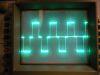
EDIT: i think ive found the resonant freq of my best HEI iggy coil.... I think its 3-5kHz...
(EDIT: from tough to trough is 178uS) I only tapped a 9V battery to the HEI iggy and captured this waveform... 5.08 Kv peak, 800 volt ring below ground. 254 uS for the main pulse (i think) 1/0.000254 = 3937 Hz, i think thats close to its resonant freq.
EDIT: i wonder if those first six concave downs could be integrated to find the arrea under the main 5kV pulse?
If there are 6 cylinders, at 3000 rpm thats (3000/60) x 6 = 300 sparks per second. 1/300 sec divided by 254uS would yield about 13. So the dead space would be 12 time periods, for each 254uS spark.
Registered Member #1451
Joined: Wed Apr 23 2008, 03:48AM
Location: Boulder, Co
Posts: 661
Wow that's really cool! It will be great to actually get wave forms from all the transformers we to get HV. If that wave form came from tapping the 9V to the primary, what are all those little pulses before the big one? Noise from the mechanical contact? I'd expect them not to be as uniform as they are.
I only ran the sweep in the sim to 10 Mhz, but at that point the attenuation had dropped a couple dB. Up at that frequency the ratio will decrease so keep that in mind when making accurate measurements.
This site is powered by e107, which is released under the GNU GPL License. All work on this site, except where otherwise noted, is licensed under a Creative Commons Attribution-ShareAlike 2.5 License. By submitting any information to this site, you agree that anything submitted will be so licensed. Please read our Disclaimer and Policies page for information on your rights and responsibilities regarding this site.


 High voltage probe for O-scope, 2 of 2, ( FABRICATION ).