If you need assistance, please send an email to forum at 4hv dot org. To ensure your email is not marked as spam, please include the phrase "4hv help" in the subject line. You can also find assistance via IRC, at irc.shadowworld.net, room #hvcomm.
Support 4hv.org!
Donate:
4hv.org is hosted on a dedicated server. Unfortunately, this server costs and we rely on the help of site members to keep 4hv.org running. Please consider donating. We will place your name on the thanks list and you'll be helping to keep 4hv.org alive and free for everyone. Members whose names appear in red bold have donated recently. Green bold denotes those who have recently donated to keep the server carbon neutral.
Special Thanks To:
Aaron Holmes
Aaron Wheeler
Adam Horden
Alan Scrimgeour
Andre
Andrew Haynes
Anonymous000
asabase
Austin Weil
barney
Barry
Bert Hickman
Bill Kukowski
Blitzorn
Brandon Paradelas
Bruce Bowling
BubeeMike
Byong Park
Cesiumsponge
Chris F.
Chris Hooper
Corey Worthington
Derek Woodroffe
Dalus
Dan Strother
Daniel Davis
Daniel Uhrenholt
datasheetarchive
Dave Billington
Dave Marshall
David F.
Dennis Rogers
drelectrix
Dr. John Gudenas
Dr. Spark
E.TexasTesla
eastvoltresearch
Eirik Taylor
Erik Dyakov
Erlend^SE
Finn Hammer
Firebug24k
GalliumMan
Gary Peterson
George Slade
GhostNull
Gordon Mcknight
Graham Armitage
Grant
GreySoul
Henry H
IamSmooth
In memory of Leo Powning
Jacob Cash
James Howells
James Pawson
Jeff Greenfield
Jeff Thomas
Jesse Frost
Jim Mitchell
jlr134
Joe Mastroianni
John Forcina
John Oberg
John Willcutt
Jon Newcomb
klugesmith
Leslie Wright
Lutz Hoffman
Mads Barnkob
Martin King
Mats Karlsson
Matt Gibson
Matthew Guidry
mbd
Michael D'Angelo
Mikkel
mileswaldron
mister_rf
Neil Foster
Nick de Smith
Nick Soroka
nicklenorp
Nik
Norman Stanley
Patrick Coleman
Paul Brodie
Paul Jordan
Paul Montgomery
Ped
Peter Krogen
Peter Terren
PhilGood
Richard Feldman
Robert Bush
Royce Bailey
Scott Fusare
Scott Newman
smiffy
Stella
Steven Busic
Steve Conner
Steve Jones
Steve Ward
Sulaiman
Thomas Coyle
Thomas A. Wallace
Thomas W
Timo
Torch
Ulf Jonsson
vasil
Vaxian
vladi mazzilli
wastehl
Weston
William Kim
William N.
William Stehl
Wesley Venis
The aforementioned have contributed financially to the continuing triumph of 4hv.org. They are deserving of my most heartfelt thanks.
Registered Member #56
Joined: Thu Feb 09 2006, 05:02AM
Location: Southern Califorina, USA
Posts: 2445
The die in the ixfx55n50 is about as big as you can get period (at least for a mosfet, the bipolars come in the puck package now), you can get slightly better thermal contact by going to something in a brick package, but usually the benefit from a brick type package is better electrical contacts (as you don't have those tiny leads to deal with) which is something you aren't really having problems with. The solution is to parallel more of them together, the IGBT crowd does this extensively (inside the large brick modules there are a number of normal to-247 sized dies soldered to the same heat spreader), but it is trickier due to the positive temp coefficient associated with MOSFETS. There is the super-20347 package you noted, but all this gives is a large heat spreader, so as long as you have good thermal contact between your mosfet and the heatsink, it won't help you much. You might want to confirm that you are in fact getting a good thermal bond, it is very possible to have a 50C+ temp drop from a mosfet to heatsink if you screw up the bond. However with the relatively small heat sinks you have I think a layer of artic silver won't be hurting you too much.
I think that at the power levels you are running for this coil, the IGBT will really win out in the end, at 200KHz they do become quite attractive. The good ones are pricy, but something like a IXGK60N60C2D1 should kick the mosfets where it hurts.
Registered Member #89
Joined: Thu Feb 09 2006, 02:40PM
Location: Zadar, Croatia
Posts: 3145
I realize that for greater power levels, the only sane solution is likely going to be usage of bricks or paralleling devices myself. I'm still optimistic on this one though, and especially with igbt's. I have some large bricks around, but they are just incompatibile with this project - they's basically require complete rebuild of the coil.
I measured the frequency the coil resonates at with small spark, and it's 145kHz - which is likely going to get even lower, perhaps as low as 100kHz with full spark load!
Looking at the ixys igbt's from your post, they at first seemed to suffer higher saturation voltage than 30N60's, but examining the graphs showed otherwise.
I'd love to put some of those puppies into this project - they also seem to come in isoplus package which can come handy for lower power projects. In short, *I really want them!* As usual digikey has them out-of-stock, and I only seem to find diodeless igbt's on ebay. Still I always preffered uninsulated devices, because they have only like half J-C resistance of insulated ones. Despite my heatsinks look small, I believe my design thermally is better than any single giant freudian heatsink with ISOTOP devices on it.
I'm definitely considering implanting some NTC chips into the IGBT's as well - this way I'll not only have a safety measure, but I also think I'll learn a lot about all things that affect temperature of the devices - what helps, and what doesn't (increasing gate drive voltage, frequency, thickness of thermal paste layer, fan speeds...)
Registered Member #599
Joined: Thu Mar 22 2007, 07:40PM
Location: Northern Finland, Rovaniemi
Posts: 624
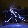
CW coils
I personally like these because there is so much metal melting power packed in short plasma flame :) Way more interesting than interrupted coils.. turn up the variac and see lights dimming
Got one with IRFP460 H-bridge
About 300V heavily filtered DC to bridge and 7 turn primary. Resonates at 300kHz. Secondary and primary wiring were almost smoking after that 20s run at ~4kW
Registered Member #89
Joined: Thu Feb 09 2006, 02:40PM
Location: Zadar, Croatia
Posts: 3145
Hi kizmo, nice to have you in the club!
Any more pics and details of your coil? I'd love to see a thread about it.
Insulated wire for the primary and PVC tube forms for secondary won't make it for long in CW operation. I built my own fiberglass tube to use for a secondary form, and copper tubing was necessary for the primary coil. Having some air blow around the base of your secondary and over the primary is of great help too - my idea was to enclose the upper level of my coil in plexi so that all the air blown through the ehatsinks is also blown over the secondary base. This would probably cause some pressure increase and decrease the efficiency of fans, and I still haven't come to getting neither the primary nor seondary so hot actually!
Your bridge design is curious - I could never find a source of sil-pad sheet suitable for this purpose, and CPU heatsinks were cheap and I thought thermal resistance would be the lowest with direct contact to the heatsink anyway.
Registered Member #1232
Joined: Wed Jan 16 2008, 10:53PM
Location: Doon tha Toon!
Posts: 881
Ooooh, CW SSTCs! Me likes!
Nice work Marko. It looks good. For increasing the power level i'd make the move to either larger die MOSFETs or parallel up a couple of something more modern than IRFP460's for more current. I found that IGBT's don't fair so well in prolonged CW duty unless they are the latest generation ones with heavily controlled current tailing.
You can get away with quite slow IGBTs in a DRSSTC where the operating frequency is quite low, and the devices can turn off softly as the current goes through zero. The small duty ratio of DRSSTC operation also massively helps keeping average switching losses under control!
In a CW SSTC with link coupled primary there's always quite a lot of inductive current flow from the inverter ("magnetising current") which means that the inverter won't switch at zero current. Even if it switches in phase with the resonator base current it will still have to interrupt at least a few amps of free-wheeling inductive current from the primary winding itself. MOSFETs love inductive loads because it minimises their turn-on losses and causes soft-recovery of the free-wheel diodes. IGBT's don't like it as much because interrupting the relatively large magnetising current causes current tailing and comparatively high turn-off losses.
Kizmo, Nice heat spreaders. Are you going to mount several MOSFETs on each one connected in parallel? It's nice to see someone paying a lot of attention to the thermal management side of the layout. Just remember to keep the devices as close together as you can to minimise stray inductance too. Particularly in the MOSFET, free-wheel diode and supply capacitor loop. This is where stray inductance is most damaging.
Marko, The "sil-pad sheet" is called Warth sheet here in UK. Made by a company called Warth Industries I think? You can also get ceramic material too that has good thermal properties and electrical insulation.
Registered Member #89
Joined: Thu Feb 09 2006, 02:40PM
Location: Zadar, Croatia
Posts: 3145
Hi Richie,
Yes, I'm aware the IGBT's are going to suffer higher switching losses than mosfets, but I still believe they are going to beat them by far in conduction losses. I'm on college again so this project is suspended for a while.
The main reason I can't put more devices in parallel is lack of space on my heatsinks - I could probably fit two devices if I didn't drill those holes, but still I'd like to parallel at least like 4 or 6 devices to be sure, and cost of such a setup would be prohibitive.
Other problem with mosfets is that there just doesn't seem to be mosfets with significantly bigger die - 55N50's, and that's about it.
The IGBT's I'm using are HGTG30N60's - according to datasheets they actually seem to be faster than those big mosfets, especially when one considers fall time which is critical because of turning off large current...
IGBT's : Mosfets:
Despite all this, I still want to remain careful, as these igbt's are hard to get and I don't want to blow them - I'll up the power in steps and measure the temperature of the devices during run.
One other thing I was thinking about, was to use series resonant primary circuit - like of a DRSSTC, but much higher impedance, with a primary of many turns and several nF of doorknob caps for the cap. This would yield two advantages:
- Good zero current switching on the igbt's, - Possibility to lower the primary significantly to decrease the probability of flashover to it.
The biggest hurdle though is building the primary coil of required high inductance in a practical volume - due to very large currents involved, simple windings of insulated wire would pretty surely just melt, while copper pipe in required amount would be both expensive and very problematic to mount in small enough volume. (I may need several tens of turns!).
Registered Member #1875
Joined: Sun Dec 21 2008, 06:36PM
Location:
Posts: 635
CW with a resonant capacitor... Are you going to let the current ultimately be limited by the ohmic resistance? That's a lot of heat and some serious voltage across your resonant capacitors...
I had an idea to drive a sstc with this topology: which drives the primary at resonance but without resonant voltage rise. But on the thread I started, people said that it wouldn't improve things much.
Perhaps it would make a difference with the power levels you are using, though.
Registered Member #89
Joined: Thu Feb 09 2006, 02:40PM
Location: Zadar, Croatia
Posts: 3145
ScotchTapeLord wrote ...
CW with a resonant capacitor... Are you going to let the current ultimately be limited by the ohmic resistance? That's a lot of heat and some serious voltage across your resonant capacitors...
Nah, the current is ultimately going to be limited by loading by the secondary. Though in order to keep the current within the safe area, a much higher impedance tank circuit would be required than in a normal DRSSTC.
I had an idea to drive a sstc with this topology: which drives the primary at resonance but without resonant voltage rise. But on the thread I started, people said that it wouldn't improve things much.
I don't know how would LSR topology work on a SSTC, I've never hears of such a proposal.
Another possibility would be to use LCLR (another commonly used in induction heaters) topology, although I'm not sure how that would work.
Registered Member #195
Joined: Fri Feb 17 2006, 08:27PM
Location: Berkeley, ca.
Posts: 1111
hi Marko, maby a larger primary with more turns and higher coupling say .5 would help. aslo water cooled fets. Steve Ward uses this aproch in his QCW coil.
have you thought of using minibricks?
That is a tough project with the heating and power diapation but very cool. The spark looks like a class-E type spark
Registered Member #89
Joined: Thu Feb 09 2006, 02:40PM
Location: Zadar, Croatia
Posts: 3145
teravolt wrote ...
hi Marko, maby a larger primary with more turns and higher coupling say .5 would help. aslo water cooled fets. Steve Ward uses this aproch in his QCW coil.
Hi teravolt - larger primary, definitely yes. More coupling - no, I already had a fire on this coil and am actually thinking to lower the primary. I'm a bit frustrated to realize that I'm too short on primary turns - I'm not going to be able to run on full available voltage - the coil just draws way too much current. I thought I have an overkill primary and that I'm going to settle for 3-4 turns, while in the end 6 proves not to be enough.
Copper pipe is not cheap so I'm unsure what to do regarding it.
Regarding steve's primary - his coil is still a pulsed one, not a completely CW coil like this - I would need much more primary turns than he has, and I just won't be able to fit that much copper pipe around the base of the coil. If I could find larger gauge litz wire it would probably work, but am not sure how to mount it.
Watercooling? Sorry, but I'm really not sure how to pull that off now - it would just be way over the budget and require rebuild of the whole coil. And since I'm already exceeding the capabilities of my mains supply, it probably doesn't make much sense anyway. If I wanted to push the CW to the end, I'd probably do something like a 50kW generator forthe supply, watercooled CM600 bricks, and series feed topology with 30kHz resonator... but it's not time for that yet.
teravolt wrote ...
have you thought of using minibricks?
Actually, no - apart being expensive and hard to find, they also have nearly twice as high internal thermal resistance compared to plain uninsulated TO247 devices. Hence I decided for them and four separate heatsinks and try to make TO247 devices give their max.
teravolt wrote ...
That is a tough project with the heating and power diapation but very cool. The spark looks like a class-E type spark
This site is powered by e107, which is released under the GNU GPL License. All work on this site, except where otherwise noted, is licensed under a Creative Commons Attribution-ShareAlike 2.5 License. By submitting any information to this site, you agree that anything submitted will be so licensed. Please read our Disclaimer and Policies page for information on your rights and responsibilities regarding this site.


 "Big Bad" the CW coil