If you need assistance, please send an email to forum at 4hv dot org. To ensure your email is not marked as spam, please include the phrase "4hv help" in the subject line. You can also find assistance via IRC, at irc.shadowworld.net, room #hvcomm.
Support 4hv.org!
Donate:
4hv.org is hosted on a dedicated server. Unfortunately, this server costs and we rely on the help of site members to keep 4hv.org running. Please consider donating. We will place your name on the thanks list and you'll be helping to keep 4hv.org alive and free for everyone. Members whose names appear in red bold have donated recently. Green bold denotes those who have recently donated to keep the server carbon neutral.
Special Thanks To:
Aaron Holmes
Aaron Wheeler
Adam Horden
Alan Scrimgeour
Andre
Andrew Haynes
Anonymous000
asabase
Austin Weil
barney
Barry
Bert Hickman
Bill Kukowski
Blitzorn
Brandon Paradelas
Bruce Bowling
BubeeMike
Byong Park
Cesiumsponge
Chris F.
Chris Hooper
Corey Worthington
Derek Woodroffe
Dalus
Dan Strother
Daniel Davis
Daniel Uhrenholt
datasheetarchive
Dave Billington
Dave Marshall
David F.
Dennis Rogers
drelectrix
Dr. John Gudenas
Dr. Spark
E.TexasTesla
eastvoltresearch
Eirik Taylor
Erik Dyakov
Erlend^SE
Finn Hammer
Firebug24k
GalliumMan
Gary Peterson
George Slade
GhostNull
Gordon Mcknight
Graham Armitage
Grant
GreySoul
Henry H
IamSmooth
In memory of Leo Powning
Jacob Cash
James Howells
James Pawson
Jeff Greenfield
Jeff Thomas
Jesse Frost
Jim Mitchell
jlr134
Joe Mastroianni
John Forcina
John Oberg
John Willcutt
Jon Newcomb
klugesmith
Leslie Wright
Lutz Hoffman
Mads Barnkob
Martin King
Mats Karlsson
Matt Gibson
Matthew Guidry
mbd
Michael D'Angelo
Mikkel
mileswaldron
mister_rf
Neil Foster
Nick de Smith
Nick Soroka
nicklenorp
Nik
Norman Stanley
Patrick Coleman
Paul Brodie
Paul Jordan
Paul Montgomery
Ped
Peter Krogen
Peter Terren
PhilGood
Richard Feldman
Robert Bush
Royce Bailey
Scott Fusare
Scott Newman
smiffy
Stella
Steven Busic
Steve Conner
Steve Jones
Steve Ward
Sulaiman
Thomas Coyle
Thomas A. Wallace
Thomas W
Timo
Torch
Ulf Jonsson
vasil
Vaxian
vladi mazzilli
wastehl
Weston
William Kim
William N.
William Stehl
Wesley Venis
The aforementioned have contributed financially to the continuing triumph of 4hv.org. They are deserving of my most heartfelt thanks.
Registered Member #397
Joined: Wed Apr 19 2006, 12:56AM
Location: Western Washington
Posts: 125
Change of plans! I was made aware that OMJ plugged my project as a feature of the week on the main page so I'm going to plug what I have so far as it'll only be up for a week. It would make little sense for everyone visiting my project only to see a couple photos. I'm lagging a bit on updated photos but this installment of photos should keep most folks happy.
A note: Some of the photos are outdated or do not correspond to the final build, or seem to be anachronistic. I changed a couple components here and there, and didn't think it worthwhile to redo for the photo documentation as nothing important has changed. All wiring has been cable laced as of today. The grid leak resistor shown is different from the variable unit used, and so on. I will do a final round of photos of the finished coil when it's completely ready. Let me preface this post that it's subject to changes/edits as necessary; its 2AM and I barely assembled this post as it was.
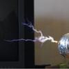
Project Inception and Goals: The project was named the Tesla Thermionic Valve Wireless Energy Transmitting Apparatus as a throwback nod to turn of the century terminology. It's inspired by vintage and antique high voltage devices from the 20th century and the modern steampunk movement of revitalizing the victorian age industrialism with a modern twist. The design elements of this tesla coil are largely based on the types of meterials used. Steel, aluminum, and plastics would create a sleek modern feel while brass, copper, and wood materials create a vintage feel of yesteryear. With all the stunning coils being built with modern materials like lexan and acrylic, I decided to go counterculture and introduce something familiar to the old guard. I suppose in this manner, both extremes of tesla coil construction methods are covered. However, I took care to use materials that should last for a very long time. Wood was completely sealed with pure tung oil. Wiring, despite being braided cloth, use modern materials that haven't had 50 years to degrade, for example.
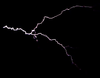
My goal for this project was to rebuild an existing single 810 VTTC circuit I had constructed about five years earlier, based off of Steve Ward's coil. It performed remarkably well, peaking at 17", and it was reasonably slick looking, utilizing HDPE construction. However it never really warmed up to me and eventually I dismantled it. I took a liking to old vintage high voltage devices over time and the steampunk movement was a nice revitalization of old world craftsmanship and skills you don't often see today.
By designing a coil utilizing the dicotemy between past and present, I modeled up a coil that keyed in on being visually attractive and unique in appearance, while being fairly easy to manufacture (with my given tooling) with prefabricated components requiring minimal machine work since I do not have access to many tools or any machine tools. The highest end tool I have at home is a large tabletop drill press. My Mitutoyo calipers cost more than my drill press. The layout is different so I expect some tuning issues to deviate from what worked on the original build but I expect performance to be similar. The addition of a variable grid leak resistor (not a feature on the last one) should give me the ability to reduce plate heating.
This is the original model which I constructed and did dimensional figures with. Things have changed a bit since then but it's remained relatively close to original intent.
Here is the original coil as it was constructed a half decade ago:
And a schematic that is up to date (I believe) reflecting the current coil configuration:
Building materials: The key to design is to pick a theme and one or two central focal points. The triode and triode guard on this project is probably considered the focal point as it takes up an entire corner quadrant. The triode guard consists of pieces of .250" copper tubing that is pounded and worked to shape. These are used as running spacers between stacks of ceramic standoffs.
I utilize an excessive amount of ceramic insulators in the build, over 50 by a rough estimate. Lots of accents were added in the way of brass and copper. Copious use of brass spheres, half spheres, and knurled thumbscrews were used to terminate threaded rods and machine screws at choice points in addition to cosmetic effect. Items such as the two tiers of brass railing serve to strengthen the inherently weak tensile strength of ceramic threads in the standoffs I used as pillars and the tube guard was comprised of lengths of formed copper tubing and ceramic spacers.
Red oak was utilized for it's durability and toughness as a hardwood which is readily available and affordable, sealed in pure tung oil which prevents moisture absorption. Everything utilizing machine screws and rods were attached to the oak decks by way of threaded wood inserts. This gives the strongest connection and also the most reusable assembly method. You can assemble and disassemble indefinitely until your fingers go numb. Wood screws have a tendancy to vary in thread pitch from one another, and constantly removing or installing them can strip out or chew up the hole because you aren't aligning the lead thread of the screw with the lead thread of the hole each and every time.
For example, the brass rails required rabbets to fit into one another at the corner joints. This would be trivial with a mill but since I had none, I used brass stock at half the finished thickness requirement and cut the half-segments to proper length before brazing them together and hand fitting/filing the perpendicular pieces until they fit neatly into one another. It ended up taking much more effort and doesn't look as good, but where there's a will, there's a way.
Pretty much every single item is raised off the mounting surface by way of some sort of standoff or spacer. This serves no practical purpose but gives it a more interesting appearance.
Many mundane items were built with special attention to make them interesting in appearance. For example. the grid leak resistor is made up of three units in series for a more compact package. The tank capacitor assembly was stylized to add visual interest, as is the RF bypass capacitor assembly.
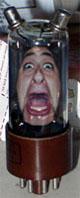
Tubes: I settled on using the 810 tube because it's a very robust transmitting triode that's had a history of successful use in the tesla coiling world. It's relatively compact size and narrow diameter makes it a reasonably-sized installation. The graphite plate ensures it's very tough and many people reported running this way over spec with no issues, even with the plate glowing bright red. They're relatively affordable and easy to find and the internal build quality makes it one of the most rugged tubes I've come across. There are several large ceramic support forms inside the tube with numerous reinforcement struts and signifigant glass support at the base. There aren't any wimpy mica supports in this thing! I have seen the larger tubes like the 833 cited as brittle and requiring kid gloves. The 810 utilizes a jumbo 4-pin base which feeds the pins through a metal/ceramic base into a bayonet sleeve socket which securely holds the tube. These sockets are also dirt cheap compared to sockets for 833's or 304TL's. They run on a 10V filament voltage with 4.5A current draw.
Since I decided to go with the steampunk and vintage theme, the decision was made to completely avoid silicon devices. the voltage doubler on the high voltage side was handled with a 3B28 xenon gas rectifier in place of a high voltage diode. This adds complexity to the project but the components still had enough room to fit nicely on the platform. The 3B28 is a drop-in replacement for the 866A mercury rectifier (my first choice) but with the major benefit of double the current handling, giving plenty of operational overhead. These operate at 2.5V with a 5A current draw. The 3B28 come in several flavors. The first one I bought had a mica shield at the top, blocking the blue glow of the tube whilst in operation. Another I purchased did not have this shield and lets an observer watch the colors while it's under load, growing brighter and larger as current increases.
Secondary coil: The secondary coil is wound on a conduit-grade 3.5" PVC tubing, which are designated by a light gray coloring. While coloring is not generally prefered when given a choice, I have seen no harm from color pigments so far. The design called for a completely sealed interior. PVC end caps were fabricated for both ends with provisions to insulate any metallic conductors such as the threaded mounted inserts and the breakout point. It consists of roughly 885 turns of #26AWG standard build magnet wire. The entire coil is baked and then coated several dozen times with polyurethane, resulting in a coating that is roughly .100" thick at the most. The top and bottom inch of the coil itself, with it's spacewound turns, is wrapped with kapton tape on top of the polyurethane coating, resulting in an amber darkening that blends it much closer to the main coil body itself, in addition to extra dielectric strength.
The top end-cap consists of a .250" thick PVC disk with the same OD as the PVC tubing itself. A secondary disk was cut from .250" phenolic sheet which was then epoxied on top of the PVC disk. The wire at the top of the coil is then routed into a recessed channel on the end cap, preventing it from abrasion and damage. The breakout point is a piece of 1/4-20 stainless threaded rod with the top half of the threads removed and the point machined to a dull point (a much more acute point would overheat very quickly and oxidize or melt). This is then fed through a beehive-type ceramic insulator. The magnet wire itself is fed underneath the ceramic insulator and makes electrical connection to the threaded rod via two washer/nut stacks to ensure electrical connectivity and reliability since it cannot be brazed to steel (assuming one can do so with silver braze, the magnet wire probably won't survive the elevated temperatures and oxidize under open flame from a torch)
The base end-cap consists of a .250" thick PVC disk with the same OD as the PVC tubing itself. A secondary disk was cut from .500" PVC sheet with an OD that matched the ID of the 3.5" tubing. These two disks were glued together. Four holes were drilled partially through and four steel 1/4-20 threaded inserts were used. These inserts allow me to mount the barebones secondary coil to a flanged base designed for this particular project, but the modularity allows me to use the coil for other purposes, if I so desired to.
The magnet wire at the base of the coil is routed through a recessed channel on the end cap, preventing it from abrasion and damage. The end is soldered to a 3.25" diameter copper sheet which has an identical four-hole bolt pattern drilled into it to match the bolt pattern of the threaded inserts in the end cap. This disk is then epoxied to the end cap, serving as the terminating junction for the base of the coil.
The base flange is a 5.500" OD .250" thick phenolic disk which serves as the mating part to the secondary coil. This flange has two patterns of bolt holes, one matching that of the secondary's end cap and another larger diameter pattern 45 degrees radially opposed for ceramic standoffs to attach the flange to the deck of the tesla coil. This base also has a copper ground sheet of 3.5" OD (with addition of a tab) which mates to the 3.25" disk on the bottom of the secondary itself when it is mechanically fastened together from underneath using 1/4-20 machine screws into the threaded inserts. An RF ground connection then can be tapped from the tab of the copper plane on the flange to an insulated feedthru directly underneath the deck to a central ground block system.
Wiring: The wiring took the longest out of everything to do. Wiring up the tesla coil took about 20 hours, mainly because I redid multiple connections multiple times in order to get wire bundled routed properly and to the right length, with neat, approvable terminations. All terminals use non-insulated crimps so they had to look presentable and not mangled by a crimping tool. The insulative jacket had to butt up against the crimps within reason and everything needed to look uniform. This was hard with cotton braided wiring because the cotton tends to fray if not stripped perfectly.
I'm using old techniques of running bundles and includes the "lost art" of cable lacing with waxed twine, which is the traditional lacing material. Cable lacing utilizes a single piece of waxed silk or cotton (nylon or similar for modernists) twine which is half-hitched (or similar running knotwork) along the length of a bundle, essentially locking wires together into a monolithic while retaining flexibility and visibility. It's main purpose was making it easy to trace, keeping the individual wires in the bundle parallel throughout the run. This technique was used heavily in avionics, telcom, and maritime wiring before the advent of zipties and it's still used today, though to a much lesser degree due to labor involved. It's mostly seen in spot tying bundles, not a full lacing job. It covers less of the wire (giving higher visibility), is less abrasive on jackets, and does not deform the jackets as much as zipties. Zipties form a circular bundle. If its too tight, it'll deform the insulative jackets. If it's too loose, individual wires can shift in the bundle, leading to difficulty in tracing runs. With cable lacing, you can lash together round, square, or any shape bundle with great security. The wax lets it grip very well so once laced up, it's very solid. It also looks darn cool! Control Panel: The control panel is made with a piece of antique, solid brass kickplate from a demolished school. It was relatively soft annealed material so working with it was simple and straightforward. Layouts were dykemed and scribed, and holes, radii, and bends were made. The panel meter holes were done with a "fly cutter" on a drill press. A stepped sheet metal drill was used for all panel holes to minimize burrs. Bends were made with the high tech method of clamping two bars of metal and pounding the bend in with a rubber mallet, and fixing and mishapen parts with more application of rubber mallet against the panel on a flat surface.
One of the last steps was letter punching. I don't have access to an engraver and it would be unbecoming of a project like this, so I resorted to a brass ball peen hammer and some handheld letter punches to stamp out some labels. The control panel has a 7.5A variable autotransformer to control line voltage to the triode plate. There is a master switch labeled "filament" in which turning this off kills all power. Turning this on will juice the filaments only. The slave switch "power" turns on power to the grid itself. A neat looking panel-mounted 3AG fuse holder is used at the bottom near the power input. Up top are two neon indicator lights for filament and power, and the two miniature panel meters monitor line voltage and line current draw. They don't have meters of this diameter (2.5") that come in other useful configurations. Ideally I'd have one to monitor filament voltages but it's fun to crank the variac and make the voltmeter climb!
With the triode assembly dominating the left quadrant, the control panel balances it by dominating the right quadrant. This gives it an asymmetrical look, which was what I as after. The photos below show what the tesla coil looked like about two weeks back. Progress is much further now but I haven't had a chance to upload photographs.
Current specifications of the coil itself: Secondary coil wire: XXXX turns of 26awg single build magnet wire, dozen layers of polyurethane Secondary coilform: 3.5" gray PVC conduit, dessicated internal volume sealed with end caps. Primary coil: 30 turns of 14awg cotton braided, lacquered stranded wire, base winding level with secondary base winding Primary coilform: 6.275"OD x 12"L sewer/drain rated PVC pipe (not SCH40/80) Tank capacitor: 1nF 80kV, two 2nF 40kV TDK XXXXXXX RF rated pulse doorknob capacitors in series. RF Bypass capacitor: 10.6nF 15kV, two 5300pF 15kV Murata RF rated doorknob capacitors in parallel Voltage doubler capacitor: 2.06uF 2.2kVAC, two 1.03uF 2.2kVAC microwave oven capacitors in parallel grid leak capacitor: 700pF 8kV mica transmitting grid leak resistor: three variable resistors in series (set at 3kohm, max of 9kohm) Voltage doubler rectification: Cetron 3B28 high voltage xenon gas rectifier High voltage transformer: Samsung 1kW ~2.1kV microwave oven transformer Variable autotramsformer: Superior Electric Powerstat 7.5A, 0-140VAC Monitoring: Simpson 2.5"OD 0-150VAC voltmeter, Simpson 2.5"OD 9-15A AC ammeter Indicators: NOS vintage neon indicator packages w/ integral current limiting resistor.
The entire collection of photos can be viewed here. There will be photographic updates as I go on as well as photos documenting other projects (which will have a simultaneous project thread running with it):
Registered Member #477
Joined: Tue Jun 20 2006, 11:51PM
Location: Seattle, WA
Posts: 546
Awesome stuff, especially the panel and wiring. The look reminds me a bit of some of my 1920's Leeds and Northrup test gear. Very slick! You and Dr. Plexiglass have both ends of the spectrum firmly covered now! When I was contemplating a VTTC, the idea of using a rectifier tube occurred to me as a cool thing to do, so I can't wait to see how it works for you. As it seems you're not far away, let me know if you come into the need for replacements, since I've got NOS mercury and gas rectifiers (3B28's and 866's) coming out my ears! Got them all for free, so I don't mind giving them away for, say, a first-hand look at your coil running?
Registered Member #540
Joined: Mon Feb 19 2007, 07:49PM
Location: MIT
Posts: 969
Wow. I really like the style of wiring. Reminds me of the old styles of construction they used for tube instruments. It looks really pretty and has that nice vintage look to it.
Registered Member #397
Joined: Wed Apr 19 2006, 12:56AM
Location: Western Washington
Posts: 125
Thank you for the kind comments so far. If anyone sees something worth criticizing, please don't hesistate to bring it up. I've been working on this tesla coil for about 2-3 months now. The original design work was done about the beginning of this year when my workload dropped and I had excess free time.
I have a bunch of ceramic insulators that I've scrounged and sniped on ebay for several months so it wasn't any particularly lucky find. It just took a lot of work and diligence (and frustration). Sorry if I sniped any of you folks in the process on ebay :) You can also get some free samples from Keystone Electronics Corp but please don't abuse it if you use that route. Companies have a tendency to start shutting down or nerfing sampling services when a ton of people max them out. Worst case scenario is buying from a place like Surplus Sales or similar. I've done this a couple times when it was an oddball size I couldn't find.
The cloth wiring is brand new production wiring with a modern PVC dielectric jacket so I wouldn't have to worry if the insulation was cracked, worn, or dirty. I purchase from Rhode Island Wiring. You can buy by-the-foot with a 10' minimum. This is basically the only place that'll do this. Every other wiring supply house wants you to buy 500' spools because cloth wiring isn't a normal item. Rhode Island Wiring specializes in reproduction cloth wiring and literally have hundreds of combinations in multiple gauges. The power cable wiring was purchased from this ebay seller before I found RI Wire.
I took a few more pictures to update it a little with all the cable bundling that wasn't shown on the previous images. It looks like the insulation in some places pulled back from the terminals after I bundled and wired it up. I'll have to redo them since exposed copper strands look ugly. I don't really want to replace the wire and re-wrap everything. I don't think tugging on the insulation will help in the long run either since it might shrink again. I don't think I left much excess to cut off the terminal and solder on a new one. We'll see.
Anode cap of the 3B28 sticking through a hole in the upper deck. Two feedthrus--one which is the HV feed from the transformer/doubler and the other leads back down to the lower deck to the RF bypass capacitor assembly. The anode cap also has the last lead feeding the tank capacitor assembly.
Bakelite case, mica capacitor. Rated to 700pF 3kV for the grid leak capacitor unit. I replaced all the steel or nickel-plated hardware with brass.
Two sets of ceramic standoffs arranged in a circular pattern. The larger inner pattern provides the four mounts that attach to the phenolic secondary flange. The short feedthru with the copper bus is the RF ground point which feeds through to the lower deck and connects to the protruding tab on the secondary flange ground plane.
Here is a close-up of the feedthru to ground the secondary coil. It's just a piece of copper strap bent to a U-shape.
This site is powered by e107, which is released under the GNU GPL License. All work on this site, except where otherwise noted, is licensed under a Creative Commons Attribution-ShareAlike 2.5 License. By submitting any information to this site, you agree that anything submitted will be so licensed. Please read our Disclaimer and Policies page for information on your rights and responsibilities regarding this site.


 The Tesla Thermionic Valve Wireless Energy Transmitting Apparatus


 have both ends of the spectrum firmly covered now! When I was contemplating a VTTC, the idea of using a rectifier tube occurred to me as a cool thing to do, so I can't wait to see how it works for you. As it seems you're not far away, let me know if you come into the need for replacements, since I've got NOS mercury and gas rectifiers (3B28's and 866's) coming out my ears! Got them all for free, so I don't mind giving them away for, say, a first-hand look at your coil running?

 Love the style. Though I'm curious to see what you plan to do with the reciever coil.