If you need assistance, please send an email to forum at 4hv dot org. To ensure your email is not marked as spam, please include the phrase "4hv help" in the subject line. You can also find assistance via IRC, at irc.shadowworld.net, room #hvcomm.
Support 4hv.org!
Donate:
4hv.org is hosted on a dedicated server. Unfortunately, this server costs and we rely on the help of site members to keep 4hv.org running. Please consider donating. We will place your name on the thanks list and you'll be helping to keep 4hv.org alive and free for everyone. Members whose names appear in red bold have donated recently. Green bold denotes those who have recently donated to keep the server carbon neutral.
Special Thanks To:
Aaron Holmes
Aaron Wheeler
Adam Horden
Alan Scrimgeour
Andre
Andrew Haynes
Anonymous000
asabase
Austin Weil
barney
Barry
Bert Hickman
Bill Kukowski
Blitzorn
Brandon Paradelas
Bruce Bowling
BubeeMike
Byong Park
Cesiumsponge
Chris F.
Chris Hooper
Corey Worthington
Derek Woodroffe
Dalus
Dan Strother
Daniel Davis
Daniel Uhrenholt
datasheetarchive
Dave Billington
Dave Marshall
David F.
Dennis Rogers
drelectrix
Dr. John Gudenas
Dr. Spark
E.TexasTesla
eastvoltresearch
Eirik Taylor
Erik Dyakov
Erlend^SE
Finn Hammer
Firebug24k
GalliumMan
Gary Peterson
George Slade
GhostNull
Gordon Mcknight
Graham Armitage
Grant
GreySoul
Henry H
IamSmooth
In memory of Leo Powning
Jacob Cash
James Howells
James Pawson
Jeff Greenfield
Jeff Thomas
Jesse Frost
Jim Mitchell
jlr134
Joe Mastroianni
John Forcina
John Oberg
John Willcutt
Jon Newcomb
klugesmith
Leslie Wright
Lutz Hoffman
Mads Barnkob
Martin King
Mats Karlsson
Matt Gibson
Matthew Guidry
mbd
Michael D'Angelo
Mikkel
mileswaldron
mister_rf
Neil Foster
Nick de Smith
Nick Soroka
nicklenorp
Nik
Norman Stanley
Patrick Coleman
Paul Brodie
Paul Jordan
Paul Montgomery
Ped
Peter Krogen
Peter Terren
PhilGood
Richard Feldman
Robert Bush
Royce Bailey
Scott Fusare
Scott Newman
smiffy
Stella
Steven Busic
Steve Conner
Steve Jones
Steve Ward
Sulaiman
Thomas Coyle
Thomas A. Wallace
Thomas W
Timo
Torch
Ulf Jonsson
vasil
Vaxian
vladi mazzilli
wastehl
Weston
William Kim
William N.
William Stehl
Wesley Venis
The aforementioned have contributed financially to the continuing triumph of 4hv.org. They are deserving of my most heartfelt thanks.
Registered Member #95
Joined: Thu Feb 09 2006, 04:57PM
Location: Norway
Posts: 1308
Wouldn't LCLR behave the same as series resonance when we use frequency power control? Running above fres will just increase the inductive reactance.
About the VCO shortcut, how much phase shift is there between the inverter output and VCO anyway? I thought the inverter output would be pretty close to the current VCO frequency, making it suitable. At least when it's only function in this case is insuring that the VCO is never running in the capacitive region. I'll try to keep the tank current large enough that I'll need to run on the inductive side most of the time, so an exact frequency lock on fres isn't necessary.
All I really want from this IH driver is control over the inverter output current, which I'm sort of loosing. I guess I'll either have to settle on constant inverter output control, or constant tank current control. Given that I'm limited to IRFP450s my inverter will be the limiting factor, so maybe inverter current control is best.
Registered Member #941
Joined: Sun Aug 05 2007, 10:09AM
Location: in a swedish junk pile
Posts: 497
Mebbe i can also experiment with this circuit and see what i can do. Tho i´d also add a tank and inverter current sense so that i can make it also regulate if current go too high.
Registered Member #95
Joined: Thu Feb 09 2006, 04:57PM
Location: Norway
Posts: 1308
Be my guest, I won't be able to try it right away as is. I drew up most of the schematic now, all that's missing is mosfet drive amplification, which is just two UCC's and a GDT. Inverter current regulation has been added as well. Quite the beast this thing is becoming.
Registered Member #1232
Joined: Wed Jan 16 2008, 10:53PM
Location: Doon tha Toon!
Posts: 881
Wouldn't LCLR behave the same as series resonance when we use frequency power control? Running above fres will just increase the inductive reactance.
The LCLR circuit is a third-order resonant network so it has one impedance minimum and one impedance maximum. These are caused by series resonance and parallel resonance respectively, whereas the series resonant tank circuit only has the impedance minimum point caused by the series resonance. Above the maximum power point both networks do present an inceasingly inductive load to the inverter.
About the VCO shortcut, how much phase shift is there between the inverter output and VCO anyway?
I don't know, you tell me! - It depends on the design: Deadtime settings, propagation delay through logic & gate-drive chips, GDT leakage inductance and damping resistance and the switching speed of the power semi's. If the PLL uses the drive signal to the inverter instead of the inverter output voltage as the control variable then it will control the VCO in such a way that the inverter's DRIVE signal is at 90 degrees to the tank voltage instead of the inverter output. The actual inverter output voltage waveform will lag the drive by some time delay and will therefore be less than 90 degrees ahead of the tank voltage. I _think_ that the outcome of doing this is that the inverter sees a slightly capacitive load when tracking resonance. It's a long time since I did this stuff, so you'll have to check the calculations. You might be able to tune out this phase shift by tweaking the PLL phase comparator to make it aim for more than 90 degrees. If it was me i'd just sense the right two waveforms.
I thought the inverter output would be pretty close to the current VCO frequency, making it suitable.
Inverter output frequency is always the same as the drive signal that is controlling the switches. Only the propagation delay (or phase shift) changes with various loadings and operating freqencies.
All I really want from this IH driver is control over the inverter output current, which I'm sort of loosing.
You can build in over-current protection for the inverter if you want, but what you really want to protect for is over-current/over-voltage in the tank circuit. With no workpiece present the tank circuit voltage and circulating current can be pumped up to tremendous values with relatively little power from the inverter because of the high Q-factor.
Registered Member #95
Joined: Thu Feb 09 2006, 04:57PM
Location: Norway
Posts: 1308
Well, it took some time to clear some projects from the waiting list but I've started on the induction heater again. I'm having problems getting the phase angle to lock at 90 degrees. While shifting through the frequency range and scoping the phase comparator output I saw that a little before 90 degrees the output (from the lowpass filter) would peak. On either side it would decrease, and at 90 degrees it was a little lower than the peak value. I'm not sure what causes this, but it seems to be messing with my control circuit. Not only that, but how can the 4046 tell where 90 degrees is if it's neither top nor bottom? The 4046 is locking to the maximum point right now I assume, which is where 90 degrees should be but isn't. The voltage and current regulators are disabled, and I'm running the circuit from low-voltage.
Fresh schematic:
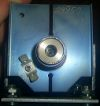
Tuned by hand for 90 degree phase shift, no feedback.
This is where the 4046 locks to when left to do as it pleases. The time div is different than the other scope shot.
Registered Member #1232
Joined: Wed Jan 16 2008, 10:53PM
Location: Doon tha Toon!
Posts: 881
Eirik what are the two waveforms being scoped in the photos?
It is the inverter output voltage and the tank circuit voltage that should be at 90 degrees to each other at the maximum power point. Both of these waveforms should be "squared up" by the time they arrive at the PLL's phase comparator, so looking at them there should show two squarewaves at the same frequency but in quadrature. The raw output of the phase-comparator should be a squarewave at twice this frequency with a 50:50 duty ratio when the inputs are exactly at 90 degrees. This is the condition that the PLL should lock to. It looks like one of your scope traces might be inverter load current from the fact that it is almost sinusoidal?
Registered Member #95
Joined: Thu Feb 09 2006, 04:57PM
Location: Norway
Posts: 1308
Whoops, forgot to mark them. The sine wave is the tank voltage, and the semi-square wave is the inverter output before the matching inductor but after the DC blocking capacitor. No squaring up or other waveform fixture yet.
I did some scoping of the XOR inputs, and the signals are no where near as square as they should be. The inverter voltage is mainly triangle, while the tank voltage is a weak sine wave. The XOR probably doesn't see their duty cycles as being 50%, and thus messes up when comparing phases. I'll fix the feedback and see if that rectifies the situation.
This site is powered by e107, which is released under the GNU GPL License. All work on this site, except where otherwise noted, is licensed under a Creative Commons Attribution-ShareAlike 2.5 License. By submitting any information to this site, you agree that anything submitted will be so licensed. Please read our Disclaimer and Policies page for information on your rights and responsibilities regarding this site.


 Induction heater as an induction launcher (now with control circuit discussion!)