If you need assistance, please send an email to forum at 4hv dot org. To ensure your email is not marked as spam, please include the phrase "4hv help" in the subject line. You can also find assistance via IRC, at irc.shadowworld.net, room #hvcomm.
Support 4hv.org!
Donate:
4hv.org is hosted on a dedicated server. Unfortunately, this server costs and we rely on the help of site members to keep 4hv.org running. Please consider donating. We will place your name on the thanks list and you'll be helping to keep 4hv.org alive and free for everyone. Members whose names appear in red bold have donated recently. Green bold denotes those who have recently donated to keep the server carbon neutral.
Special Thanks To:
Aaron Holmes
Aaron Wheeler
Adam Horden
Alan Scrimgeour
Andre
Andrew Haynes
Anonymous000
asabase
Austin Weil
barney
Barry
Bert Hickman
Bill Kukowski
Blitzorn
Brandon Paradelas
Bruce Bowling
BubeeMike
Byong Park
Cesiumsponge
Chris F.
Chris Hooper
Corey Worthington
Derek Woodroffe
Dalus
Dan Strother
Daniel Davis
Daniel Uhrenholt
datasheetarchive
Dave Billington
Dave Marshall
David F.
Dennis Rogers
drelectrix
Dr. John Gudenas
Dr. Spark
E.TexasTesla
eastvoltresearch
Eirik Taylor
Erik Dyakov
Erlend^SE
Finn Hammer
Firebug24k
GalliumMan
Gary Peterson
George Slade
GhostNull
Gordon Mcknight
Graham Armitage
Grant
GreySoul
Henry H
IamSmooth
In memory of Leo Powning
Jacob Cash
James Howells
James Pawson
Jeff Greenfield
Jeff Thomas
Jesse Frost
Jim Mitchell
jlr134
Joe Mastroianni
John Forcina
John Oberg
John Willcutt
Jon Newcomb
klugesmith
Leslie Wright
Lutz Hoffman
Mads Barnkob
Martin King
Mats Karlsson
Matt Gibson
Matthew Guidry
mbd
Michael D'Angelo
Mikkel
mileswaldron
mister_rf
Neil Foster
Nick de Smith
Nick Soroka
nicklenorp
Nik
Norman Stanley
Patrick Coleman
Paul Brodie
Paul Jordan
Paul Montgomery
Ped
Peter Krogen
Peter Terren
PhilGood
Richard Feldman
Robert Bush
Royce Bailey
Scott Fusare
Scott Newman
smiffy
Stella
Steven Busic
Steve Conner
Steve Jones
Steve Ward
Sulaiman
Thomas Coyle
Thomas A. Wallace
Thomas W
Timo
Torch
Ulf Jonsson
vasil
Vaxian
vladi mazzilli
wastehl
Weston
William Kim
William N.
William Stehl
Wesley Venis
The aforementioned have contributed financially to the continuing triumph of 4hv.org. They are deserving of my most heartfelt thanks.
Registered Member #30
Joined: Fri Feb 03 2006, 10:52AM
Location: Glasgow, Scotland
Posts: 6706
Hi James,
Did you read the manual I published for the PLL driver?
I'd very much appreciate if you could try the tuning procedure in there and tell me if it works! :P It needs beta testing. BTW, every coil I ever made requred the loop gain trimmer turned to minimum resistance (ie, maximum loop gain)
Basically the tuning lights only come on if the phase detector tries to move the VCO outside of the allowable range. So when the coil is in tune, both lights go out. If you have the phasing backwards, you should find it impossible to get the lights to go out. (IIRC.)
Registered Member #505
Joined: Sun Nov 19 2006, 06:42PM
Location: Yorkshire!
Posts: 329
Hi Steve,
Yes, I've been using the manual to set up the coil, it's very useful. However I think that from what I've read (and also based on your reply) that I've got some wiring problems somewhere in the PLL.
My measurements show that the frequency can be set using the trimmer pot, but that moving the tap point does not affect the operating frequency. That either points to the current transformer or something in the VCO loop that isn't wired correctly. Given that the tuning LEDs don't light whatever the phasing of the CT I'm inclined to look at the VCO loop first.
Bugger. Time to do some fixing I guess. Thanks for the feedback Steve, I shall use the tuning guide once I've got the circuitry working properly and If I have any suggestions I'll be sure to feed them back to you. Thanks for documenting it in the first place.
Registered Member #146
Joined: Sun Feb 12 2006, 04:21AM
Location: Austin Tx
Posts: 1055
Im not sure about the 280A at only 22V input, its not possible you grabbed the wrong resistor (say 4.7 ohms?) on accident?
Where are you probing on the half-bridge to see that waveform? If its the supply rails, then im pretty surprised because you have a very nice lytic on there which should keep it pretty solid.
Registered Member #30
Joined: Fri Feb 03 2006, 10:52AM
Location: Glasgow, Scotland
Posts: 6706
The waveform probably is fine, it's likely to be the scope probe and leads picking up the magnetic field from the primary that makes it look so awful.
BTW, sorry if the circuit isn't working, I always find it difficult to troubleshoot stuff like that over the internet, but I'll do my best! :s
Check the VCO control voltage at IC12 pin 7 with a scope. It should normally be at half the supply rail, so 7.5V on the boards I built. If you deliberately mistune it, you should be able to see the voltage ramp up or down over the course of a burst as it tries to retune itself, and finally fall back to 7.5V at the end of the burst. The tuning lights don't come on until it gets +/-0.7V away from 7.5V.
Registered Member #505
Joined: Sun Nov 19 2006, 06:42PM
Location: Yorkshire!
Posts: 329
The voltage was measured on one leg of the bridge relative to the bridge -ve supply. The spikes look like switching noise, some of which is caused by the small amount of deadtime that is purposefully introduced by the controller. There appears to be an underlying sine wave that is 90º out of phase with the capacitor current which doesn't sound too unreasonable.
As for the current transformer, I've used 10 x 4R7s in parallel to give 0.47 ohms. The sums say 10mV/A, the scope was set to 10:1 divide so the 22.81V is actually 2.281V. This gives 228A pk-pk or just 114A peak. 25V supply, 350us burst, current from supply was a couple of amps IIRC. I will verify with a Tektronix current probe later today. All these measurements were made without a secondary in place, just the primary tank.
As for the circuit, don't worry, it's more likely my dodgy soldering than your design:P I'll give your suggestions a spin at lunchtime.
Thanks for all the input James
EDIT
OK, I found the problems - my dodgy soldering, I told you!
PLL feedback loop took output from pin 1 not pin 2
Solder short across pins 1 and 2 of the integrator capacitor in the VCO feedback
Loop gain pot output was connected to pin 4 of the op-amp (ground) instead of pin 2
Once these were fixed, the tuning LED flickers when I turn it on and the PLL appears to track the frequency. I can now follow Steve's tuning guide properly.
Registered Member #505
Joined: Sun Nov 19 2006, 06:42PM
Location: Yorkshire!
Posts: 329
I finished winding the secondary this week, the motorised jig was rubbish for turning the coilform when winding and putting the wire on under tension so I wound it by hand - 2.5 hours in total. The motor came in very handy for turning the coilform when applying two coats of varnish though!
Overall quality of the coilform isn't fanatastic, there are a few lumps and bumps due to scuffs in the gas pipe coil former I used. t'll be reet.
I'm going to take the components into work, assemble the complete system and fire (did I say fire?) it up. I'm expecting sparks (and hopefully no explosions) before the week is out...
Registered Member #505
Joined: Sun Nov 19 2006, 06:42PM
Location: Yorkshire!
Posts: 329
Bennem wrote ...
All the best with 'the fire up' at work I take it that you don't work in an office?......lol
I do work in an office, but there is a small workshop in one corner of the building away from everything else that is as good a place as any for initial testing. When everything is working properly and it comes to the bigger sparks, I shall take everything home because I have a fairly large garden!
Besides, people at the office have sen the base unit on my desk and want to see a demo at work!
Registered Member #505
Joined: Sun Nov 19 2006, 06:42PM
Location: Yorkshire!
Posts: 329
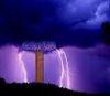
I'm just running up the system at low voltages (sub 30V) and with a scope probe about 8 inches from the top and at the primary tapping point calculated to give the same resonant frequency as the secondary I get this characteristic. No breakout occurred during this testing. EDIT: Also, I haven't changed the tuning (frequency) control since I added the secondary. This might be the problem?
I've tried moving the tap point a bit (±1 turn) but it doesn't seem to go away.
Questions: 1) Is this behaviour expected for a DRSSTC? I thought they operated in a pulsed CW mode rather than the energy sloshing about between primary and secondary.
2) Should I be trying to move the tap point around / changing my value of MMC to try and remove this notching?
3) I know that frequency splitting causes a lower pole and an upper pole and that the lower pole is generally preferred (increase number of turns on primary by moving tap). How do I know when I'm tuned to the lower pole? Will the PLL driver just select the dominant pole and run at that frequency?
4) Will this notching disappear when breakout and streamer loading occurs?
Registered Member #30
Joined: Fri Feb 03 2006, 10:52AM
Location: Glasgow, Scotland
Posts: 6706
Unlike the ordinary feedback driver, the PLL driver chooses whichever pole you tell it to. Now the secondary is in place, as you adjust the tuning control you should find two settings where both tuning lights go out. These are your two pole frequencies.
I always seemed to get the best results by choosing the higher of the two frequencies, but with the primary tuned to a slightly lower frequency than the secondary. Choosing the lower one would always cause violent flashovers for some reason.
I think certain settings of the primary tap, combined with a low coupling coefficient, will make it impossible to get the lights to go out at one or other of the pole frequencies. But I don't know much more at this point.
This site is powered by e107, which is released under the GNU GPL License. All work on this site, except where otherwise noted, is licensed under a Creative Commons Attribution-ShareAlike 2.5 License. By submitting any information to this site, you agree that anything submitted will be so licensed. Please read our Disclaimer and Policies page for information on your rights and responsibilities regarding this site.


 "Inazuma" Mk.1 DRSSTC