If you need assistance, please send an email to forum at 4hv dot org. To ensure your email is not marked as spam, please include the phrase "4hv help" in the subject line. You can also find assistance via IRC, at irc.shadowworld.net, room #hvcomm.
Support 4hv.org!
Donate:
4hv.org is hosted on a dedicated server. Unfortunately, this server costs and we rely on the help of site members to keep 4hv.org running. Please consider donating. We will place your name on the thanks list and you'll be helping to keep 4hv.org alive and free for everyone. Members whose names appear in red bold have donated recently. Green bold denotes those who have recently donated to keep the server carbon neutral.
Special Thanks To:
Aaron Holmes
Aaron Wheeler
Adam Horden
Alan Scrimgeour
Andre
Andrew Haynes
Anonymous000
asabase
Austin Weil
barney
Barry
Bert Hickman
Bill Kukowski
Blitzorn
Brandon Paradelas
Bruce Bowling
BubeeMike
Byong Park
Cesiumsponge
Chris F.
Chris Hooper
Corey Worthington
Derek Woodroffe
Dalus
Dan Strother
Daniel Davis
Daniel Uhrenholt
datasheetarchive
Dave Billington
Dave Marshall
David F.
Dennis Rogers
drelectrix
Dr. John Gudenas
Dr. Spark
E.TexasTesla
eastvoltresearch
Eirik Taylor
Erik Dyakov
Erlend^SE
Finn Hammer
Firebug24k
GalliumMan
Gary Peterson
George Slade
GhostNull
Gordon Mcknight
Graham Armitage
Grant
GreySoul
Henry H
IamSmooth
In memory of Leo Powning
Jacob Cash
James Howells
James Pawson
Jeff Greenfield
Jeff Thomas
Jesse Frost
Jim Mitchell
jlr134
Joe Mastroianni
John Forcina
John Oberg
John Willcutt
Jon Newcomb
klugesmith
Leslie Wright
Lutz Hoffman
Mads Barnkob
Martin King
Mats Karlsson
Matt Gibson
Matthew Guidry
mbd
Michael D'Angelo
Mikkel
mileswaldron
mister_rf
Neil Foster
Nick de Smith
Nick Soroka
nicklenorp
Nik
Norman Stanley
Patrick Coleman
Paul Brodie
Paul Jordan
Paul Montgomery
Ped
Peter Krogen
Peter Terren
PhilGood
Richard Feldman
Robert Bush
Royce Bailey
Scott Fusare
Scott Newman
smiffy
Stella
Steven Busic
Steve Conner
Steve Jones
Steve Ward
Sulaiman
Thomas Coyle
Thomas A. Wallace
Thomas W
Timo
Torch
Ulf Jonsson
vasil
Vaxian
vladi mazzilli
wastehl
Weston
William Kim
William N.
William Stehl
Wesley Venis
The aforementioned have contributed financially to the continuing triumph of 4hv.org. They are deserving of my most heartfelt thanks.
Registered Member #6038
Joined: Mon Aug 06 2012, 11:31AM
Location: Salado, TX
Posts: 248
On the low-power test, yes I am turning it off. At full power, I can't see the bridge voltage as I cannot scope it at that voltage (not isolated and too high for my probe). The interrupter I am using has a burst length to 300uS but even at 300uS it still rings down after 150uS. That makes me think the energy is being transferred before it has rung up fully. Does this make sense? If that is true, what would cause that? I am running at low BPS so duty cycle protection in the interrupter should not be not an issue.
Is it possible for you to reduce the tank impedance by adding more primary capacitance? Also is it possible for you to find a way to increase the voltage to your bus? Perhaps you might be able to find a 208 or 240V outlet (e.g. from the dryer). Your CM300 bridge should be good for lots more volts.
Oh one thing I noticed - your toroid looks very high off your secondary coil's top winding. I'd drop the toroid lower otherwise you might start to see corona discharge from the top of your secondary's winding.
[edit] I see you're using a half bridge instead of a full bridge (is that correct?). Try to get 500-600VDC on your bus with 208V rectified. You'll be able to get a faster ring up and you'll get significantly longer sparks with a shorter drive time.
Registered Member #6038
Joined: Mon Aug 06 2012, 11:31AM
Location: Salado, TX
Posts: 248
loneoceans wrote ...
Is it possible for you to reduce the tank impedance by adding more primary capacitance? Also is it possible for you to find a way to increase the voltage to your bus? Perhaps you might be able to find a 208 or 240V outlet (e.g. from the dryer). Your CM300 bridge should be good for lots more volts.
Oh one thing I noticed - your toroid looks very high off your secondary coil's top winding. I'd drop the toroid lower otherwise you might start to see corona discharge from the top of your secondary's winding.
[edit] I see you're using a half bridge instead of a full bridge (is that correct?). Try to get 500-600VDC on your bus with 208V rectified. You'll be able to get a faster ring up and you'll get significantly longer sparks with a shorter drive time.
It will be difficult to change the architecture now - not much room for more caps. I am using an H-bridge. Changing bus voltage is tough as all components are rated for the 340v. Few places I go have 220v power, so I wanted to keep it at 120v and try get the 4' I am looking for. The specs are very close to Eric Goodchilds 2400w Twin coils (running at 380v bus) so I believe 4' is a realistic expectation. I can lower the toroid - that would be possible.
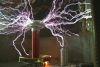
I just filmed the coil with corresponding CT monitoring of the primary as I sweep the interrupter from zero to 300uS. You can see that after 150uSec, the primary rings down (never going over 375A), even though the burst length increases. I am really starting to suspect that the interrupter is shutting down despite what I think it's doing. I have not scoped the gate signal while running so maybe try that next.
Ok - I just scoped the GDT input and the burst length goes to a full 300uSec. So can't blame the interrupter any more. Therefore the primary is ringing down at 150uS on it's own - presumably when all energy is transferred.
Registered Member #834
Joined: Tue Jun 12 2007, 10:57PM
Location: Brazil
Posts: 644
The current at 0:11 in the video looks normal. A longer burst may result in longer streamers, since a quite long streamer is already developed. Are you using some feedback? You can look at both sides of the bridge, to see if the switches are operating correctly.
Registered Member #6038
Joined: Mon Aug 06 2012, 11:31AM
Location: Salado, TX
Posts: 248
The current at 0:11 in the video looks normal. A longer burst may result in longer streamers, since a quite long streamer is already developed. Are you using some feedback? You can look at both sides of the bridge, to see if the switches are operating correctly.
The feedback is a 625:1 CT on the primary between MMC and Primary Coil. When I tested the bridge at lower power I confirmed that both sides are working properly. I think we would see an imbalanced oscillation if it was not.
I would recommend to double the primary capacitance
I just did a test by replacing the 4"x17" toroid with a 6"x19" and got significantly better results. Obviously retuned the primary, but the current rose close to 500A with 46" sparks. My assumption is that more energy can be stored in the secondary system allowing a longer ring-up?
I have 5 strings of 4x2000v caps (0.15uF) making up the 0.1875uF. This was designed using the Kaizer Calculator with reliability in mind. I tried to over-engineer everything. If I need more capacitance I can do that, but it's an expensive upgrade, so I need to be sure.
[edit] - I just ran the Kaizer cap calculator again and if I re-configure the MMC to 3 in series and 6 strings, I will have .3uF (vs .1875) and still well below the peak voltage. If safe rule of thumb is 10 x bus voltage I am at 3400v. According to the calculator I should see 3300v peak. This may work without buying more caps
I just filmed the coil with corresponding CT monitoring of the primary as I sweep the interrupter from zero to 300uS. You can see that after 150uSec, the primary rings down (never going over 375A), even though the burst length increases.
The video suggests strongly, that arc loading limits primary current at the point where current doesn't increase anymore with longer bursts. The effect of arc loading looks much like a series resistor appearing in the primary tank. Formally it can be described as R = Zpri/Qpri, where Qpri is an effective Q caused by secondary loading. This has been discussed in . Without going into the details there: Qpri is independent of Zpri as long as primary resonant frequency remains unchanged and also secondary parameters. That implies, that the effective series resistance R will decrease proportionally to a decrease of Zpri. That is what Kizmo suggested in order to get primary current up. Another method to increase Qpri and thus get to higher currents is to detune the primary to lower frequencies, i.e. to tap your primary for larger inductance. Changing secondary Q by adding e.g. more top load also can change Qpri. The effect is not so predictable, since that will also change tuning.
Registered Member #6038
Joined: Mon Aug 06 2012, 11:31AM
Location: Salado, TX
Posts: 248
Thanks Uspring, I was just reading that post you referenced last night. Very interesting stuff. One good thing about a coil not working as expected is that you get to learn a lot
I also read a post where Steve Conner spoke about ideal surge impedance being 5 to 10 times inverter impedance - given by (4/pi)*(DC bus voltage/current limit). If I read this correctly, for my bus voltage of 340v and CM300 the Inverter impedance is 0.72. (divided by 2 for the H-bridge). The tank impedance with the increased capacitance is now 6.33ohms or 8.8 times inverter impedance. Assuming my understanding of the equation is correct. It was 13.6x with the previous MMC. So this does sound better. Putting it all back together now - will see how that works.
[edit] well, I rebuilt the MMC (now .3uF) and while I was about it, re-designed the layout of components, beefed up the connectors etc. Redid the ZCS tuning and did a whole set of measurements before putting all back together. Results were definitely improved by increasing the Cpri. By the time I got it tuned and running properly, she was delivering 48" arcs with a peak current of 500A. The OCD is set at 600 and only trip with ground strikes. I have not tried the bigger toroid, but I am happy with the results. As I said i am looking for super-reliability rather than max spark length. 4ft is manageable for most indoor performance.
Thanks to all for help in resolving this. Hopefully this thread will serve others too running into this issue.
Just a note on reliability - with your primary impedance at 6.3 ohms, at 500Apk, the MMC will see 3165V. You'll see that the CDEs are rated 500VAC per capacitor. Ideally for best reliability I would size the MMC using the AC voltage rating (not DC, and remember the AC rating is for 50/60Hz not tesla frequencies). Sadly this will mean 4x the number of capacitors!
However for hobby use, the MMC you have should be fine. :) Well done on the build and glad it worked out well!
This site is powered by e107, which is released under the GNU GPL License. All work on this site, except where otherwise noted, is licensed under a Creative Commons Attribution-ShareAlike 2.5 License. By submitting any information to this site, you agree that anything submitted will be so licensed. Please read our Disclaimer and Policies page for information on your rights and responsibilities regarding this site.


 Tuning for max power