If you need assistance, please send an email to forum at 4hv dot org. To ensure your email is not marked as spam, please include the phrase "4hv help" in the subject line. You can also find assistance via IRC, at irc.shadowworld.net, room #hvcomm.
Support 4hv.org!
Donate:
4hv.org is hosted on a dedicated server. Unfortunately, this server costs and we rely on the help of site members to keep 4hv.org running. Please consider donating. We will place your name on the thanks list and you'll be helping to keep 4hv.org alive and free for everyone. Members whose names appear in red bold have donated recently. Green bold denotes those who have recently donated to keep the server carbon neutral.
Special Thanks To:
Aaron Holmes
Aaron Wheeler
Adam Horden
Alan Scrimgeour
Andre
Andrew Haynes
Anonymous000
asabase
Austin Weil
barney
Barry
Bert Hickman
Bill Kukowski
Blitzorn
Brandon Paradelas
Bruce Bowling
BubeeMike
Byong Park
Cesiumsponge
Chris F.
Chris Hooper
Corey Worthington
Derek Woodroffe
Dalus
Dan Strother
Daniel Davis
Daniel Uhrenholt
datasheetarchive
Dave Billington
Dave Marshall
David F.
Dennis Rogers
drelectrix
Dr. John Gudenas
Dr. Spark
E.TexasTesla
eastvoltresearch
Eirik Taylor
Erik Dyakov
Erlend^SE
Finn Hammer
Firebug24k
GalliumMan
Gary Peterson
George Slade
GhostNull
Gordon Mcknight
Graham Armitage
Grant
GreySoul
Henry H
IamSmooth
In memory of Leo Powning
Jacob Cash
James Howells
James Pawson
Jeff Greenfield
Jeff Thomas
Jesse Frost
Jim Mitchell
jlr134
Joe Mastroianni
John Forcina
John Oberg
John Willcutt
Jon Newcomb
klugesmith
Leslie Wright
Lutz Hoffman
Mads Barnkob
Martin King
Mats Karlsson
Matt Gibson
Matthew Guidry
mbd
Michael D'Angelo
Mikkel
mileswaldron
mister_rf
Neil Foster
Nick de Smith
Nick Soroka
nicklenorp
Nik
Norman Stanley
Patrick Coleman
Paul Brodie
Paul Jordan
Paul Montgomery
Ped
Peter Krogen
Peter Terren
PhilGood
Richard Feldman
Robert Bush
Royce Bailey
Scott Fusare
Scott Newman
smiffy
Stella
Steven Busic
Steve Conner
Steve Jones
Steve Ward
Sulaiman
Thomas Coyle
Thomas A. Wallace
Thomas W
Timo
Torch
Ulf Jonsson
vasil
Vaxian
vladi mazzilli
wastehl
Weston
William Kim
William N.
William Stehl
Wesley Venis
The aforementioned have contributed financially to the continuing triumph of 4hv.org. They are deserving of my most heartfelt thanks.
Registered Member #1773
Joined: Tue Oct 21 2008, 06:56PM
Location: Poland
Posts: 93
Hi. I want to do that experiment came to similar conclusions. Actually induction heater controller is very similar to the controller drsstc. In both cases we are to the right so that the phase shift of structure transistors switch to the zeros current ZCS.
Currently I designed, I hope the final version of the PCB. Is similar to the popular predikter. I decided to use some of OCD (Over Current Detector). I used LM7171 (very fast op-amp), AD790 (very fast comparator) as the original, the first opamp with current transformer is an ideal voltage rectifier two halves of the positive and negative voltage waveform of the transformer. I want OCD system worked as quickly as possible. Another part of the driver is a PLL 4046, also signals to hit the 74HC109 break after activation OCD zeros excluded the current driver.
I hope that today will guide subsequent trial and plug in ready driver for the heater circuit. At the moment I checked the operation of the controller without a resonant circuit;)
Registered Member #1143
Joined: Sun Nov 25 2007, 04:55PM
Location: Vilnius, Lithuania
Posts: 721
Very nice project and very nice idea. If i have some time/money i will try to develop STM32F7 based induction heater solution with pulse skipping for power modulation, as well as PLL to compensate for delay, and OCD just like in normal DRSSTC, that will turn off transistor on nearest zero current crossing, or 2x period ( latch-up situation, but at this point, it will not help i think) And as usual, AMOLED screen with touchscreen for power, voltage, current monitoring as well as other cool stuff.
I have all power electronics, only controller is needed :(
Registered Member #1773
Joined: Tue Oct 21 2008, 06:56PM
Location: Poland
Posts: 93
It's fun. Could using a controller stm try to create a kind of automatic phase shift settings during startup.
Current limit borrowed from predikter-and works well. In the scheme of OCD in preditker is a capacitor setting off time after detecting overcurrent. I used 10uF instead of the original 4.7nF. I lengthened the time 3-5s exemption. Current limit has to work in several situations. Definitely going to work in the event of a short circuit resonant eg. When heated object to tip over. Current limit is also supposed to work when operating winding will be blank.
I have a problem with the current measurement using transformers. The problem is that the resistor power is long enough ... I decided to do this instead of CTs feedback as in the old version that is hooked into a resonant capacitor. Fortunately that the voltage on the capacitor resonant current rises evenly.
I add pictures on and off the IGBT. The bridge consists of four IGBTs. 1US / div
Registered Member #33
Joined: Sat Feb 04 2006, 01:31PM
Location: Norway
Posts: 971
Thanks for the comments guys. I can absolutely recommend the pulse skipping (often called pulse density modulation in papers), as you can control power smoothly without losing ZCS.
Some news on the project. I tried using the induction heater for practical stuff. The biggest limitation now is power dissipation in the coupling transformer primary. When running for a few minutes earlier, it got quite hot, and when trying to run it for longer this week, the insulation on the winding melted and the primary shorted, taking out the IGBTs. The wire I used was teflon insulated stranded 16 AWG silver plated, with two wires in parallel, and when it failed it was carrying around 10 A RMS at 300 kHz.
I suspected the skin effect losses were significant, so I tried replacing it with some heavy litz from an induction stove, 144 strands of 0.25mm for a total cross section of 7 mm^2. This is not ideal for the frequency in question, but should be significantly better than the smaller non-litz wire I used before in terms of skin effect losses. When testing it, there was hardly any improvement. It turns out most of the copper losses were caused by the proximity effect, especially near the secondary where the current density is very high. From a paper I found: "Simply increasing the wire size won't help; unlike skin effect, a larger than optimum wire size can dramatically increase the losses, especially for multiple winding layers. Litz wire is not a panacea and may also increase losses"
To try to minimize this problem, I soldered some copper plates to the secondary. These should hopefully spread out the proximity losses, to avoid overheating the primary near the secondary, and also help with cooling the primary by heat conduction to the water cooled secondary. If needed, the primary can be potted in thermally conductive glue, to help heat conduction to the secondary. I haven't tested it yet, but will update the thread with results
Registered Member #2310
Joined: Wed Aug 19 2009, 08:04PM
Location: Santa Catarina - Brazil
Posts: 169
I'm having problems with the transformer too, It dissipates a lot of heat and this is the worst thing that I saw on the series resonant topology, thinking about goind bat to the Parallel because is much easier to control the power with the air gap on the l-match inductor and much easier to change the number of turns on it...
Registered Member #1773
Joined: Tue Oct 21 2008, 06:56PM
Location: Poland
Posts: 93
I use six wires 1.25mm each twisted tightly and that's enough with 15KW at 550VDC power to the bridge. What is the frequency of generating power control? I understand that to control the power you generate a square wave signal with a fixed frequency and the duty cycle depends on the power. Is the heater does not work generates weird sounds?
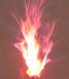
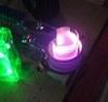
The photo shows a graphite crucible, power 12KW, crucible itself weighs 2kg and warmed up in a few minutes :)
Registered Member #33
Joined: Sat Feb 04 2006, 01:31PM
Location: Norway
Posts: 971
Gabriel35 wrote ...
I'm having problems with the transformer too, It dissipates a lot of heat and this is the worst thing that I saw on the series resonant topology, thinking about goind bat to the Parallel because is much easier to control the power with the air gap on the l-match inductor and much easier to change the number of turns on it...
Yeah, the transformer design is one of the most challenging parts. I think a successful design needs to both minimize dissipation and get rid of the heat that is produced in the windings and the core. Understanding the proximity effect is the dominating challenge for me now, I know my new transformer is a lot better but I don't know if it's good enough yet. If it isn't, then thermal glue and foil winding is the next step.
Non-isolated LCLR avoids this problem, and also has some other advantages. I've already written up something about the relative advantages and disadvantages of the different tank circuit arrangements:
A lot has been said about the relative merits of TCSR (transformer coupled series resonant) and LCLR tank circuits. I've seen statements that TCSR has a better power factor or better efficiency than LCLR. This is however not true, and both configurations are pretty similar in practice. I've melted steel with both, and there was no real difference in performance. This is assuming that the matching network is chosen properly, and I assume that people who have had bad experiences with LCLR have had badly chosen component values in the matching network. Theory and simulations also back this up, the phase and amplitude response is very similar between the two configurations near the resonant frequency. Both have a phase angle that crosses through zero at the resonant frequency, so both will have unity power factor at some frequency. Both are also used industrially. There are hower some practical differences between them, which I will try to sum up here.
Edit March 2016: I've done some more reading and simulations, and I have to add some corrections to this. What I wrote about the power factor of LCLR tank circuits only applies at light loading. At heavier loading of the work coil, the inverter current phase angle never crosses zero. This means that the LCLR has worse power factor and no possibility of ZCS with heavier loading.
LCLR advantages: *Tolerant of work coil shorts, inverter sees a light inductive load *Can be made without ferrite in the power circuit *Little added parasitic inductance between the tank capacitor and the work coil, this can be very important with low inductance work coils *Wiring inductance between inverter and tank circuit will just add to the matching inductor *Easy to drive a tank from multiple bridges combined through matching inductors *If the matching inductor is placed near the bridge, the transmission line voltage is sinusoidal, resulting in less radiated noise when the tank is far away *Mechanically nice tank arrangement
LCLR disadvantages: *Bad power factor with heavy loading *No galvanic isolation without an extra transformer *Requires a matching inductor that can also induction heat surrounding metal *Current phase angle is not monotonic below resonance, making it hard for a simple PLL to always find resonance *Matching steals a small part of the tank capacitance. Not usually a big problem
TCSR advantages: *Unity power factor is possible over a wide range of loading contitions *Inherent galvanic isolation *No matching inductor is required *The phase angle of the inverter current is always monotonic on both sides of resonance, so inverter current feedback can be used
TCSR disadvantages: *Can be mechanically awkward to make the tank circuit *Inverter is presented with a capacitive load if workcoil is shorted *Inductance between the inverter and tank is reflected through the matching transformer, stealing tank VARs. *Isolation transformer design is difficult at higher frequencies and powers, mostly due to the proximity effect, transformer coupled LCLR has similar challenges.
I use six wires 1.25mm each twisted tightly and that's enough with 15KW at 550VDC power to the bridge.
What frequency are you running at? This is the same cross section i used in the litz wire, and it overheated quickly. At high frequency, the coupling transformer design is very challenging compared to lower frequencies.
What is the frequency of generating power control? I understand that to control the power you generate a square wave signal with a fixed frequency and the duty cycle depends on the power. Is the heater does not work generates weird sounds?
I run at 250 - 600 kHz depending on the work coil. Power control is generated from the measured tank voltage, the control circuit will skip whole cycles when the tank circuit voltage is larger than the target.
Registered Member #2310
Joined: Wed Aug 19 2009, 08:04PM
Location: Santa Catarina - Brazil
Posts: 169
The cycle skipping seems to be a great ideia. Do you have plans on posting some schematics of it soon?
What are the switches you are currently using?
In my IH, I'm using the TCSR now for testing and I think that the material of my cheap toroids is bad or not made for that purpose because the windings do not heat, the only thing that heats up are the toroidal cores...
Registered Member #33
Joined: Sat Feb 04 2006, 01:31PM
Location: Norway
Posts: 971
Gabriel35 wrote ...
The cycle skipping seems to be a great ideia. Do you have plans on posting some schematics of it soon?
What are the switches you are currently using?
In my IH, I'm using the TCSR now for testing and I think that the material of my cheap toroids is bad or not made for that purpose because the windings do not heat, the only thing that heats up are the toroidal cores...
I've attached the current schematic. The bus voltage sensing is not isolated from mains, but it will be in the final version. The current solution is just something I threw together to see if it would stabilize the circuit, see earlier posts in the thread for more info on this.
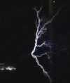
I'm currently using Fairchild FGH40T65SPD, they are very cheap and low loss. I've only killed IGBTs once, and that was when the primary of the coupling transformer melted and shorted. I've attached an image of the broken IGBTs. As you can see, the dies are very small, but they can still handle switching significant power on account of their very low losses. I prefer to have low loss IGBTs instead of older devices with larger dies that are more robust but more lossy.
What core are you using for the coupling transformer and what frequency are you operating at?
This site is powered by e107, which is released under the GNU GPL License. All work on this site, except where otherwise noted, is licensed under a Creative Commons Attribution-ShareAlike 2.5 License. By submitting any information to this site, you agree that anything submitted will be so licensed. Please read our Disclaimer and Policies page for information on your rights and responsibilities regarding this site.


 Adventures in induction heating