If you need assistance, please send an email to forum at 4hv dot org. To ensure your email is not marked as spam, please include the phrase "4hv help" in the subject line. You can also find assistance via IRC, at irc.shadowworld.net, room #hvcomm.
Support 4hv.org!
Donate:
4hv.org is hosted on a dedicated server. Unfortunately, this server costs and we rely on the help of site members to keep 4hv.org running. Please consider donating. We will place your name on the thanks list and you'll be helping to keep 4hv.org alive and free for everyone. Members whose names appear in red bold have donated recently. Green bold denotes those who have recently donated to keep the server carbon neutral.
Special Thanks To:
Aaron Holmes
Aaron Wheeler
Adam Horden
Alan Scrimgeour
Andre
Andrew Haynes
Anonymous000
asabase
Austin Weil
barney
Barry
Bert Hickman
Bill Kukowski
Blitzorn
Brandon Paradelas
Bruce Bowling
BubeeMike
Byong Park
Cesiumsponge
Chris F.
Chris Hooper
Corey Worthington
Derek Woodroffe
Dalus
Dan Strother
Daniel Davis
Daniel Uhrenholt
datasheetarchive
Dave Billington
Dave Marshall
David F.
Dennis Rogers
drelectrix
Dr. John Gudenas
Dr. Spark
E.TexasTesla
eastvoltresearch
Eirik Taylor
Erik Dyakov
Erlend^SE
Finn Hammer
Firebug24k
GalliumMan
Gary Peterson
George Slade
GhostNull
Gordon Mcknight
Graham Armitage
Grant
GreySoul
Henry H
IamSmooth
In memory of Leo Powning
Jacob Cash
James Howells
James Pawson
Jeff Greenfield
Jeff Thomas
Jesse Frost
Jim Mitchell
jlr134
Joe Mastroianni
John Forcina
John Oberg
John Willcutt
Jon Newcomb
klugesmith
Leslie Wright
Lutz Hoffman
Mads Barnkob
Martin King
Mats Karlsson
Matt Gibson
Matthew Guidry
mbd
Michael D'Angelo
Mikkel
mileswaldron
mister_rf
Neil Foster
Nick de Smith
Nick Soroka
nicklenorp
Nik
Norman Stanley
Patrick Coleman
Paul Brodie
Paul Jordan
Paul Montgomery
Ped
Peter Krogen
Peter Terren
PhilGood
Richard Feldman
Robert Bush
Royce Bailey
Scott Fusare
Scott Newman
smiffy
Stella
Steven Busic
Steve Conner
Steve Jones
Steve Ward
Sulaiman
Thomas Coyle
Thomas A. Wallace
Thomas W
Timo
Torch
Ulf Jonsson
vasil
Vaxian
vladi mazzilli
wastehl
Weston
William Kim
William N.
William Stehl
Wesley Venis
The aforementioned have contributed financially to the continuing triumph of 4hv.org. They are deserving of my most heartfelt thanks.
Registered Member #543
Joined: Tue Feb 20 2007, 04:26PM
Location: UK
Posts: 4992
Have you thought of applying an analogue voltage derived from a variable resistor to your FET gate? If this restores good order, you will know where the problem - or at least part of it - is lying low.
Registered Member #3447
Joined: Fri Nov 26 2010, 11:10PM
Location: North Jersey
Posts: 97
That certainly makes sense. Let's see, simulations suggest that at 4mA, the gate voltage on an IRF830, should be around 4.5V. I'll just build a voltage divider off a 9V battery and we'll see if the oscillation persists. Hopefully I can test this theory tomorrow... Thanks.
Registered Member #133
Joined: Fri Feb 10 2006, 10:27PM
Location: Pensacola, Florida
Posts: 47
Common mode noise is likely getting into your 24 V SMPS and is affecting its feedback loop. I have encountered this when driving pulsed loads (even with expensive commercial power supplies). Place a common mode choke in line with your 24 V supply (i.e. – wind the 24 V power lead and the return lead together on a high permeability toroid).
A few other notes: 1) 100 Ohms may be too large for the gate resistance. 2) Place decoupling capacitors across your op-amp power inputs. (Try 0.01 uF to start with.) 3) Keep your a) op-amp output-to-MOSFET gate path and b) MOSFET source-to-inverting op-amp path close to each other in order to keep this loop area small. If you are using wires to your MOSFET, then twist the gate and source wires across the entire length. (You do not want noise introduced here.) 4) Placement and proper layout for the op-amps is important for noise free operation.
Registered Member #3447
Joined: Fri Nov 26 2010, 11:10PM
Location: North Jersey
Posts: 97
Steve-
Thanks for the tip. I'll go ahead and get some ferrite and check it out, too.
Oh, troubleshooting!
EDIT: I just ordered four 1" ferrite toroids. I'm planning on rewiring the 24V SMPS 110VAC input wires to be twisted together and spiraled around one of these toroids.I eyeballed the 1.8A rating of my SMPS and guessed that this would be enough ferrite.
EDIT: The permeability of these toroids is 2400. I don't think that's as fancy as the nano-crystalline ones for sale now, but I figure that I'll just counter-wind two 18 gauge jacketed wires as far as I can and see what happens.
Registered Member #3447
Joined: Fri Nov 26 2010, 11:10PM
Location: North Jersey
Posts: 97
I just conducted the following experiment:
(1) Disconnected SMPS input lines (left the ground connected to chassis ground and output return to chassis ground). (2) Connect 24V battery in place of SMPS. (3) Everything else as was.
Results: (1) Tube lit in similar steady manner and very low current (500uA). (2) Fans again slowed a little, but very little audible oscillation (lower frequency). (3) As I turned the current up to 2mA, the frequency of the audible oscillation increased, and the fans slowed to almost a complete stop.
It looks like the current control is working pretty well. The cascode circuit was designed to have a very high dynamic impedance because of the negative resistance characteristics of laser tubes, so it may be that the oscillations are kinda normal. Their effect on the fans is unexpected, though.
EDIT: And in response to above, I guess the power supply isn't tripping... Even batteries won't keep the fans running at full speed. They just slow down progressively as current is increased to 2mA from a few hundred microamps.
Registered Member #3447
Joined: Fri Nov 26 2010, 11:10PM
Location: North Jersey
Posts: 97
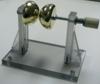
In the file shown below, you will see that the triode output (cathode) wire is bundled with a number of other wires on its way to and from the indicated fuse. The 24V fan's positive line passes through this bundle. Could they be coupled in some way? The current is so very low that it's hard to imagine that a significant induction could affect a battery... I'll keep looking for the source of the 24V screwup.
Registered Member #30
Joined: Fri Feb 03 2006, 10:52AM
Location: Glasgow, Scotland
Posts: 6706
If your tubes are oscillating, the RF could be confusing the brushless motor control circuit in the fan. The average current may be only 4mA, but it could be in the form of nasty little RF bursts with high peak power.
It is possible to have RF and audible oscillations at the same time. The effect is called squegging.
Again I recommend adding a grid stopper resistor at least.
Registered Member #3447
Joined: Fri Nov 26 2010, 11:10PM
Location: North Jersey
Posts: 97
Do you think that a potentiometer would be handy in this application? I'm not sure what value would be best, guessing somewhere from 1.5k to 100k. As you can see, I'm got a 20kOhm resistor tied to ground in parallel with the decoupling cap and neon, but I don't think that forms the proper RC filter with the valves input capacitance... Am I right in thinking that this resistor should be in series with the other components?
I wish I had an oscilloscope to get an idea of what "kind" of RF noise I was dealing with.
Registered Member #89
Joined: Thu Feb 09 2006, 02:40PM
Location: Zadar, Croatia
Posts: 3145
Hi gecko
Look what your circuit does: it's a linear regulator with full gain of your amplifier (tens/hundreds of thousands) being wired in the negative feedback path. The opamp itself as well as the mosfet will always introduce some delay in the feedback loop which translates a phase shift which increases proportionally with the frequency - result of which is, that at a certain frequency this finally reaches 180 degrees, turning your negative feedback into positive. And if your system still has overall gain greater than 1 at this frequency, it will oscillate just like any other astable multivibrator, tesla coil or whatever.
Since you did nothing to lower the HF gain of your TL084 (which is a pretty wideband opamp with cutoff at 4Mhz IIRC), oscillation here is pretty much a certainty. High dynamic gain of the mosfet in linear range probably makes it even worse.
Hence the infamous RC network we always see on TL494's and whereever. There is a series RC going from error amp output back to it's - input, It's purpose should now be obvious - at high frequencies the capacitor acts as low impedance and the resistor alone is virtually connected between - and amp output. For this to help though we need one more resistor in feedback path which will form a divider with the first one.
Now we've gotten an amplifier which has it's maximum gain at DC for minimum error and very low gain at high frequencies to prevent oscillations.
There are various ways of optimizing this network (since it after all slows down the response), but if your regulator is only intended to work with static load and reference then you could probably get satisfied by just slapping a random big cap until oscillations stop.
I'd probably start with something like 1k resistor on feedback wire and a 1uF cap or something like that.
There will also be assorted other random things that help - such as, swapping your opamp for slower, crappier one like 741, which acts as a low pass filter in itself. Other things like increasing the mosfet gate resistor value, or filtering the voltage across the mosfet with a capacitor could happen to help in a similar way.
Mosfets are also somewhat troublesome parts for linear use. For a circuit like this I'd probably just use a 200V darlington instead (which I think is more than enough for the tube to be off).
This site is powered by e107, which is released under the GNU GPL License. All work on this site, except where otherwise noted, is licensed under a Creative Commons Attribution-ShareAlike 2.5 License. By submitting any information to this site, you agree that anything submitted will be so licensed. Please read our Disclaimer and Policies page for information on your rights and responsibilities regarding this site.


 Oscillations Redux