If you need assistance, please send an email to forum at 4hv dot org. To ensure your email is not marked as spam, please include the phrase "4hv help" in the subject line. You can also find assistance via IRC, at irc.shadowworld.net, room #hvcomm.
Support 4hv.org!
Donate:
4hv.org is hosted on a dedicated server. Unfortunately, this server costs and we rely on the help of site members to keep 4hv.org running. Please consider donating. We will place your name on the thanks list and you'll be helping to keep 4hv.org alive and free for everyone. Members whose names appear in red bold have donated recently. Green bold denotes those who have recently donated to keep the server carbon neutral.
Special Thanks To:
Aaron Holmes
Aaron Wheeler
Adam Horden
Alan Scrimgeour
Andre
Andrew Haynes
Anonymous000
asabase
Austin Weil
barney
Barry
Bert Hickman
Bill Kukowski
Blitzorn
Brandon Paradelas
Bruce Bowling
BubeeMike
Byong Park
Cesiumsponge
Chris F.
Chris Hooper
Corey Worthington
Derek Woodroffe
Dalus
Dan Strother
Daniel Davis
Daniel Uhrenholt
datasheetarchive
Dave Billington
Dave Marshall
David F.
Dennis Rogers
drelectrix
Dr. John Gudenas
Dr. Spark
E.TexasTesla
eastvoltresearch
Eirik Taylor
Erik Dyakov
Erlend^SE
Finn Hammer
Firebug24k
GalliumMan
Gary Peterson
George Slade
GhostNull
Gordon Mcknight
Graham Armitage
Grant
GreySoul
Henry H
IamSmooth
In memory of Leo Powning
Jacob Cash
James Howells
James Pawson
Jeff Greenfield
Jeff Thomas
Jesse Frost
Jim Mitchell
jlr134
Joe Mastroianni
John Forcina
John Oberg
John Willcutt
Jon Newcomb
klugesmith
Leslie Wright
Lutz Hoffman
Mads Barnkob
Martin King
Mats Karlsson
Matt Gibson
Matthew Guidry
mbd
Michael D'Angelo
Mikkel
mileswaldron
mister_rf
Neil Foster
Nick de Smith
Nick Soroka
nicklenorp
Nik
Norman Stanley
Patrick Coleman
Paul Brodie
Paul Jordan
Paul Montgomery
Ped
Peter Krogen
Peter Terren
PhilGood
Richard Feldman
Robert Bush
Royce Bailey
Scott Fusare
Scott Newman
smiffy
Stella
Steven Busic
Steve Conner
Steve Jones
Steve Ward
Sulaiman
Thomas Coyle
Thomas A. Wallace
Thomas W
Timo
Torch
Ulf Jonsson
vasil
Vaxian
vladi mazzilli
wastehl
Weston
William Kim
William N.
William Stehl
Wesley Venis
The aforementioned have contributed financially to the continuing triumph of 4hv.org. They are deserving of my most heartfelt thanks.
Registered Member #63
Joined: Thu Feb 09 2006, 06:18AM
Location:
Posts: 1425
We all love pics.. so, err, here, have some pics. =-D
I've been carefully raising the volts this morning from 12V to 19V to 25V to 50V, and now he's drawing about 4A w/ tightish coupling but too little loading capacitance, from the looks of the scope? eee.... at least my heatsink stays cold.
Maybe I should throw an RF choke in there for the hell of it... and more power supply decoupling -- I only have 2.72uF of decoupling caps on there, hehe
Registered Member #29
Joined: Fri Feb 03 2006, 09:00AM
Location: Hasselt, Belgium
Posts: 500
BP wrote ... hmm, I wonder if that little spike in my DS waveform corresponds to the same miller spike in my GS waveform.
The tiny spike on the left side of your waveform is likely a little bit of harmonic generation going on as a result of parasitic resonance somewhere in your circuit. Likewise, the "undershoot" on the right side of each "half-sine" could be the result voltage drop across a little bit of parasitic lead inductance during a short period of "reverse current" flowing through the drain. (This figure is from a plot of a Spice simulation of a class-E amplifier...note the reverse drain current that flows for a short time during the transistor turn-on stage... parasitic lead inductance was not included in the simulation, so the voltage waveform does show this effect. Perhaps, if I had included a couple of nH of lead inductance, this reverse voltage would appear, like it does in your o-scope measurement....)
The origin of this current appears to be indeed due charging of the gate-drain capacitance during transistor turn-on (Cgd). Initially, I would not have expected the current transient to be so large.... However, if one estimates the charge moved during the transient, it comes to about 75nC...which is wthin the same order of magnitude of the data-sheet specified Miller charge for this transistor (2SK2698: 22nC for Vdd=400V, Vgs=10V, Id=15A...my simulation conditions:estimate 75nC for Vdd=0V, Vgs=12V, Id=0A).
EDIT: BP: In your post where you increase the supply voltage, you look like you are getting lots of high-order harmonic generation. A little bit of quenching resistance may be in order in the gate circuit to kill those high frequency components.. (I could just be blowing hot air out my arse too, given I don't even know what your circuit looks like or if it's your o-scope probes that are resonating! )
Registered Member #30
Joined: Fri Feb 03 2006, 10:52AM
Location: Glasgow, Scotland
Posts: 6706
I think the undershoots are caused by mismatching in such a way that the drain current is underdamped and tries to shoot below zero. Richie's Class-E page explains all. But they don't seem too drastic and it all seems to be performing well. I don't think the RF choke or extra decoupling would make much difference.
Registered Member #29
Joined: Fri Feb 03 2006, 09:00AM
Location: Hasselt, Belgium
Posts: 500
Steve, this simulation is not for a tesla coil, but for a matched-to-50-ohms class-E amplifier (perhaps I should have said so..sorry!) Any class-E output matching circuit is going to be slightly underdamped (Q of 2-5 or so) because by definition, it relies on "ringing" at the fundamental frequency to define the transistor turn-on and turn-off times.
I don't think the body-diode was forced into conduction in the simulations during the reverse current times, because Vds was very close to zero. What is happening in reality, may be another matter! ;)
The RF choke may help reduce coupling to power leads if you're having problems related to interference (I used one for mine, because RF coupling to power leads in my 4.5MHz coil caused the digital meters on my bench power supply to go insane, the gas heater's computer to lock up and the kitchen clock to freak out....)
Registered Member #89
Joined: Thu Feb 09 2006, 02:40PM
Location: Zadar, Croatia
Posts: 3145
I've done a similar thing last winter, it's a rather small class-E coil with on board power supply, all powered by a 12V battery. I thought about wearing that thing as a hat, but I think there will be a grounding problem then... The PCB is 100 x 120mm and contains all needed parts, including the secondary. It's a very simple boost converter that powers the class E amp and it's not running very stable, but good enough for a tesla coil.
Great little coil liquidfire And welcome to (new) 4HV..
I decided to use mazzili driver controlled by external PWM regulator. I got an inspiration for this from some small CCFL inverters wich use similar topology (mazzili/royer powers a transformer efficiently and it is externally controlled by additional PWM IC.
IC eventually takes feedback from oscillator's output.
Now I got into a big trouble finding an adequate transformer for ZVS. Untouched ATX transformer works but can't generate low enough output voltage for input power.
Firstly I tried to get the core apart by throwing the transformer in boiling water, but it wasn't even lcose to weaken the epoxy.
I had to heat up the transformer to 300+ degrees with hot air fan to let the core go.
Ferrite forms microfractures when abused lik this and breaks easily.
I broke one core instantly, another I broke later handling it. Tiny cracks are everywhere and I don't think such cores are usable anymore.
I had a sized ferrite pot somewhere but I found it broken too (ages old thng).
Such things are to be bought (impossible in croatia). A bigger ferrite toroid would be even neater for use as I don't need lots of windings.
We all love pics.. so, err, here, have some pics. =-D
I've been carefully raising the volts this morning from 12V to 19V to 25V to 50V, and now he's drawing about 4A w/ tightish coupling but too little loading capacitance, from the looks of the scope? eee.... at least my heatsink stays cold.
Maybe I should throw an RF choke in there for the hell of it... and more power supply decoupling -- I only have 2.72uF of decoupling caps on there, hehe
Looks neat bp, now it could be right time to put a small topload (a little toroid would look great on your small resonator) on it
Allows some extra sparks to be drawn, and even breaks out on it's own if coil is propertly made.
It must be a monster heatsink to dissipate 20 watts over there and stay cold. Seeing your sparks I must admit they look a bit ghetto for 200 Watts of input power. You should be kicking 4-5 cm streamers without, and maybe 10 with interrupter. (look at steve ward's coil).
I should also put an interrupter to my coil if I want to pwn steve ward at some stage
For decoupling cap I used 0.68uF and it was fine. If you want to be sure about it just put a main filter cap on it's place.
You don't need RF chokes and such stuff, especially in series with your primary.
I tried to put a variable inductor there (with few turns of thick wire) but it just suffocated the output, and I couldn't tune class E stage with it noticeably so I removed it.
I think the undershoots are caused by mismatching in such a way that the drain current is underdamped and tries to shoot below zero. Richie's Class-E page explains all. But they don't seem too drastic and it all seems to be performing well. I don't think the RF choke or extra decoupling would make much difference.
Steve, I think you also need a small class E coil like such.
Nothing on your site for long (OK we are expecting Odin here, soon )
Registered Member #162
Joined: Mon Feb 13 2006, 10:25AM
Location: United Kingdom
Posts: 3140
I have experimented with a CFPR (zvs) 12V powered invertor, Modulation is easy, The easy/inefficient way is a linear regulator feeding the dc inductor, (pMOSFET with a potentiometer +12V to 0V, wiper to gate for variable CURRENT)
Chopping the dc supply to the dc inductor with a pMOSFET and 555 gives output modulation (but with complex waveforms).
You should have fast diodes from 0V to drain and drain to +12V in either case.
I used 2 x NTP27N06 for the invertor and 1 x MTP23P06 for the chopper not because they're the best, but because I was given a few by Adam Horden. I used an MPP core for the dc inductor (similar to iron powder) which works VERY well and gapped-ferrite for the resonant/invertor transformer. If interrested I'll see if I can dig up the circuit and post some waveforms. (I may have to reconstruct it so patience will be required)
P.S. For my relatively low frequency resonator (<100 kHz) the CFPR inductance can be a few turns of copper tubing TC primary but my 80W CW in a 6" dia 28" high secondary was not impressive. (I used a 12V 7AH VRLA battery and MMKP capacitors)
Registered Member #316
Joined: Mon Mar 13 2006, 01:30PM
Location: Marietta, GA
Posts: 212
I think even in Croatia you should be able to find black and white TV's. Just get the flyback out of one of those and pull out the core. Also, I never heard you say anything about it needing to be battery-powered. You could try to find a little variac and then just rectify it. What is the mains voltage in Croatia? If it's 230 you could just make a voltage divider and then rectify it.
Registered Member #89
Joined: Thu Feb 09 2006, 02:40PM
Location: Zadar, Croatia
Posts: 3145
Sulaiman: Well I abandoned boost converter because of inefficiency. High voltage mosfets/IGBT's would dissipate too much power.
Flyback is neater because I can use low woltage, low Rds-ON mosfets for lower loss. But it is hard switching and still relatively lossy. I also imagine trouble with matching the output.
Maybe it could later be improved to double-ended drive with deadtime control, etc.
*updated*
I don't think that 'interrupting' a ZVS would do any good, and putting additional buck seems pointless regarding efficiency. By chopping gate supplies or main power I only get wierd waveform wich is difficult to modulate, and I put stress to ZVS unless I sinchronize turn-offs.
I have some SG3525-s here anyway, so the'l be put to use.
I think even in Croatia you should be able to find black and white TV's. Just get the flyback out of one of those and pull out the core. Also, I never heard you say anything about it needing to be battery-powered. You could try to find a little variac and then just rectify it. What is the mains voltage in Croatia? If it's 230 you could just make a voltage divider and then rectify it.
Im' definitely not going to drag a vaiac with this (even smallest I seen are 2x times bigger than the coil itself). Powering the coil from 220V would again be inadequate as I would need a 'big' mains transformer to powr electronics. It swould be just silly to see all that to be dragged together with such a tiny coil.
Even smallest flyback cores I have would hardly fit onto my power supply board, but I *could* mock out something of them too if I get really desperate. They are really an overkill for the power level I use.
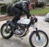
This is an older pic of the coil, it wasn't even class-E at that time and was rather of ghetto internalconstruction, but general look is the same
Edited:
omg sparks:
I finally gave the coil some more power, this time it is 45 volts at some 70 watts.
If I put a breakout point onto the coil It spews about 6 cm wide streamer.
Arc hits 11cm as maximum (I admit I now had some more starting voltage, about 60 volts) but it disconnects and continues to live as beautiful brushy streamer breaking out on itself from topload. Coil sometimes breaks out from topload on it's own.
Electric field from the topload causes interesting 'pinch' effect to the plasma, and about 2 cm from topload it keeps narrow beam wich is incredibly hot, looking like bright yellow flame. Then it forms branches like 'standard' CW streamers.
I have to disconnect the coil from supply if that streamer settles in place, as it would make celluloid ball explode if it settles too long in one place.
I definitely need a better topload =)
When I bring the wire closer I can draw very hot, flame-like arc wich is about 6cm long.
I also heated out a hell of small heatsink, after few minutes mosfet easily reaches boiling point. Now I just need an interrupter and a little more input power...
Registered Member #30
Joined: Fri Feb 03 2006, 10:52AM
Location: Glasgow, Scotland
Posts: 6706
Hey Firkragg
That looks great! What frequency does it work at?
BTW, I think a ZVS with a buck converter before it isn't such a bad idea as it sounds. If you used the 12V winding on an ATX transformer as the primary, it could get you into the 150V ball park. I once tried a ZVS using the 5v winding as the primary, and the output gave 300-350V DC when rectified (with a voltage doubler iirc)
And of course the buck converter lets you regulate the output.
This site is powered by e107, which is released under the GNU GPL License. All work on this site, except where otherwise noted, is licensed under a Creative Commons Attribution-ShareAlike 2.5 License. By submitting any information to this site, you agree that anything submitted will be so licensed. Please read our Disclaimer and Policies page for information on your rights and responsibilities regarding this site.


 Class E SSTC thread


 )
)

 I don't think the RF choke or extra decoupling would make much difference.