If you need assistance, please send an email to forum at 4hv dot org. To ensure your email is not marked as spam, please include the phrase "4hv help" in the subject line. You can also find assistance via IRC, at irc.shadowworld.net, room #hvcomm.
Support 4hv.org!
Donate:
4hv.org is hosted on a dedicated server. Unfortunately, this server costs and we rely on the help of site members to keep 4hv.org running. Please consider donating. We will place your name on the thanks list and you'll be helping to keep 4hv.org alive and free for everyone. Members whose names appear in red bold have donated recently. Green bold denotes those who have recently donated to keep the server carbon neutral.
Special Thanks To:
Aaron Holmes
Aaron Wheeler
Adam Horden
Alan Scrimgeour
Andre
Andrew Haynes
Anonymous000
asabase
Austin Weil
barney
Barry
Bert Hickman
Bill Kukowski
Blitzorn
Brandon Paradelas
Bruce Bowling
BubeeMike
Byong Park
Cesiumsponge
Chris F.
Chris Hooper
Corey Worthington
Derek Woodroffe
Dalus
Dan Strother
Daniel Davis
Daniel Uhrenholt
datasheetarchive
Dave Billington
Dave Marshall
David F.
Dennis Rogers
drelectrix
Dr. John Gudenas
Dr. Spark
E.TexasTesla
eastvoltresearch
Eirik Taylor
Erik Dyakov
Erlend^SE
Finn Hammer
Firebug24k
GalliumMan
Gary Peterson
George Slade
GhostNull
Gordon Mcknight
Graham Armitage
Grant
GreySoul
Henry H
IamSmooth
In memory of Leo Powning
Jacob Cash
James Howells
James Pawson
Jeff Greenfield
Jeff Thomas
Jesse Frost
Jim Mitchell
jlr134
Joe Mastroianni
John Forcina
John Oberg
John Willcutt
Jon Newcomb
klugesmith
Leslie Wright
Lutz Hoffman
Mads Barnkob
Martin King
Mats Karlsson
Matt Gibson
Matthew Guidry
mbd
Michael D'Angelo
Mikkel
mileswaldron
mister_rf
Neil Foster
Nick de Smith
Nick Soroka
nicklenorp
Nik
Norman Stanley
Patrick Coleman
Paul Brodie
Paul Jordan
Paul Montgomery
Ped
Peter Krogen
Peter Terren
PhilGood
Richard Feldman
Robert Bush
Royce Bailey
Scott Fusare
Scott Newman
smiffy
Stella
Steven Busic
Steve Conner
Steve Jones
Steve Ward
Sulaiman
Thomas Coyle
Thomas A. Wallace
Thomas W
Timo
Torch
Ulf Jonsson
vasil
Vaxian
vladi mazzilli
wastehl
Weston
William Kim
William N.
William Stehl
Wesley Venis
The aforementioned have contributed financially to the continuing triumph of 4hv.org. They are deserving of my most heartfelt thanks.
Registered Member #95
Joined: Thu Feb 09 2006, 04:57PM
Location: Norway
Posts: 1308
This is amazing! I've been following this thread since it started, and have to say I'm impressed by what you guys and gals have discovered. I'm tinkering away at my own setup right now, and hope to try some American 2X2A tubes I have.
Your pinhole images are fascinating Leslie, you're using an intensifier tube to see this if I'm not mistaken? I'm interested in the details of the pinhole itself too. Reading about pinhole cameras it would seem we need a micrometer sized hole to get focused images, if using a practical focal length.
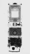
Oh, and to help aid visualization of the x-ray source, here's Radu's enhanced images beside Stella's heat-shield pics. The detail is incredible!
Registered Member #1134
Joined: Tue Nov 20 2007, 04:39PM
Location: Bonnie Scotland
Posts: 351
radhoo wrote ...
Can you post a photo showing your setup for this experiment? What have you used to record those pictures with such an excellent quality?
ps2: Les' images with some additional software enhacement. I would really like to know more on how these photos where made. Great job, so many details visible!
I will take some photos at the beginning of the week, as I am away till Monday night.
The apparatus consists of one of my very sensitive x-ray Fluoroscopes described here, (except this version uses a Generation II tube),and a lead pinhole camera assembly.
An 8 inch long truncated cone was fabricated from lead sheet. The tip of the cone is flat, with a large hole drilled in it to permit mounting a pinhole of any size. . The pinhole is about 0.05mm across, and was made in a separate thin piece of lead.
This is simply mounted on the front of the fluoroscope, and pointed at the x-ray source. The output screen in viewable in real time to dark adapted eyes, but the digital camera requires a 15s exposure to produce a bright enough image from the screen.
The cone of the pinhole camera is made so long as to permit some decent magnification of the x-ray sources.
Next week I will take some real close ups of the anode, and try and setup the webcam to take some very long exposures, to see if the weaker emissions the tube can be imaged in this way.
Registered Member #1938
Joined: Sun Jan 25 2009, 12:44PM
Location: Romania
Posts: 699
Hi Eirik!
Thanks for joining in!
I'm a bit confused: Are you saying Les is using an intensifier tube? I assume he is also using a fluorescent screen of some kind to filter the regular light (there is plenty while the tube is powered on) from the x-rays. Les, we'd like to see your setup. LE: cross-posting: ok, looking forward to see your pictures. thanks for the details!
The American 2X2 might not be very good at this, I've used 2 different tubes with not much output (there are some pics a few posts above).
Stella, thanks for the graph a few comments: - it shows a point-like target - bremsstrahlung radiation goes in the electron direction, so if the target is the shield, this is not the cause for the abundant x-rays - which leaves: the K X-rays (now I wonder what the shield is made of: you've mentioned it was magnetic some time ago). So for the point-like target , the graph shows a sphere like distribution all around the target (I see a small circle).
One thing that doesn't seem right with the current shield target idea: The target is white-hot! The shield doesn't even get red...
Registered Member #543
Joined: Tue Feb 20 2007, 04:26PM
Location: UK
Posts: 4992
radhoo wrote ...
Stella, thanks for the graph a few comments: - it shows a point-like target - bremsstrahlung radiation goes in the electron direction, so if the target is the shield, this is not the cause for the abundant x-rays - which leaves: the K X-rays (now I wonder what the shield is made of: you've mentioned it was magnetic some time ago). So for the point-like target , the graph shows a sphere like distribution all around the target (I see a small circle).
One thing that doesn't seem right with the current shield target idea:
This is how an electron bombardment target looks like at 50KV pd: White-hot!
The shield doesn't even get red...
I think perhaps I should have added a few words of explanation to the graph.
You will notice that at 50keV, there is significant radiation at 90° to the electron beam, but at 500keV the bremmstrahlung follows the direction of the electron beam much more closely. i.e. the tendency of the bremmstrahlung to follow the electron beam direction is energy dependent.
Now, if you have 40kV on your anode, about 1% of the X-rays produced will have an energy of 40keV, and all the rest will have less, down the lowest energy that can transmitted by the glass envelope (say 15keV) tending to become more and more isotropic with decreasing energy.
And to these increasingly isotropic bremmstrahlung can be added the isotropic characteristic rays of the elements in the target.
Your observations about heat dissipated in the anode seem to confuse X-ray energy with tube current and with fluence. You could have 100kV across a micro field emission tube which drew but 1μA, for a total power of 100mW. It would emit a tiny amount of 100keV rays, but their fluence - quantity of photons per square metre - would be very low indeed, and the tube would not get significantly warm.
Conversely, you can find Be window XRD tubes with just 10kV on the anode that gobble up 1kW or more and need high pressure water cooling.
On a separate note: FILTRATION
Filtration with Al, Cu, or Ag foils may improve the resolution of the pin-hole images.
Registered Member #1134
Joined: Tue Nov 20 2007, 04:39PM
Location: Bonnie Scotland
Posts: 351
Uzzors wrote ...
Your pinhole images are fascinating Leslie, you're using an intensifier tube to see this if I'm not mistaken? I'm interested in the details of the pinhole itself too. Reading about pinhole cameras it would seem we need a micrometer sized hole to get focused images, if using a practical focal length.
Thanks and yes, its a GenII image intensifier tube with GADOX scintillator bonded to the face plate, like my fluoroscopes. The pinhole is 0.05mm diameter. Micron sized would be better, but even with a system gain of around 40,000 very long exposures would be needed. (a project for next week).
Oh and thanks for the comparison pics post, it certainly clarifies what is being observed here.
radhoo wrote ...
White-hot!
The shield doesn't even get red...
It certainly looks white hot, however that coating is brilliantly fluorescent under the impact of electrons! Note the comparatively dark uncoated region at the end of the heater.
If you really push the tube the shield can be raised to yellow heat under the impact of electrons.
Proud Mary wrote ...
On a separate note: FILTRATION
Filtration with Al, Cu, or Ag foils may improve the resolution of the pin-hole images.
The fluoroscope is already filtered with 0.5mm Aluminium. A smaller hole and longer exposure is what is needed now.
Registered Member #1938
Joined: Sun Jan 25 2009, 12:44PM
Location: Romania
Posts: 699
Proud Mary wrote ...
Your observations about heat dissipated in the anode seem to confuse X-ray energy with tube current and with fluence. You could have 100kV across a micro field emission tube which drew but 1μA, for a total power of 100mW. It would emit a tiny amount of 100keV rays, but their fluence - quantity of photons per square metre - would be very low indeed, and the tube would not get significantly warm. Conversely, you can find Be window XRD tubes with just 10kV on the anode that gobble up 1kW or more and need high pressure water cooling.
What you're saying here is P=UxI and that more electron intensity will produce more x-ray intensity "fluence?", while the potential difference is responsible for the energy and penetration power of the x-ray photons. The x-ray intensity is what follows the inverse square law (since it's radiant energy) and we're all using it to keep us safe while experimenting. etc. Perhaps I wasn't clear, my idea was a bit different: we have different dissipation on the filament as compared to the relatively bigger shield, but still it would have been nice to actually see the shield being struck by electrons and emanating heat.
plazmatron wrote ...
It certainly looks white hot, however that coating is brilliantly fluorescent under the impact of electrons! Note the comparatively dark uncoated region at the end of the heater. If you really push the tube the shield can be raised to yellow heat under the impact of electrons.
Yes, it looks white hot, and when you unplug the supply you will see it get orange, then red, brown and black. About the shield, I would like to see it getting yellow, but I guess the filament would melt first. Still for such an emission intensity, I would have expected the target to become more visible while under electron fire.
This site is powered by e107, which is released under the GNU GPL License. All work on this site, except where otherwise noted, is licensed under a Creative Commons Attribution-ShareAlike 2.5 License. By submitting any information to this site, you agree that anything submitted will be so licensed. Please read our Disclaimer and Policies page for information on your rights and responsibilities regarding this site.


 Vacuum Rectifiers X-rays report


 I've been following this thread since it started, and have to say I'm impressed by what you guys and gals have discovered. I'm tinkering away at my own setup right now, and hope to try some American 2X2A tubes I have.