If you need assistance, please send an email to forum at 4hv dot org. To ensure your email is not marked as spam, please include the phrase "4hv help" in the subject line. You can also find assistance via IRC, at irc.shadowworld.net, room #hvcomm.
Support 4hv.org!
Donate:
4hv.org is hosted on a dedicated server. Unfortunately, this server costs and we rely on the help of site members to keep 4hv.org running. Please consider donating. We will place your name on the thanks list and you'll be helping to keep 4hv.org alive and free for everyone. Members whose names appear in red bold have donated recently. Green bold denotes those who have recently donated to keep the server carbon neutral.
Special Thanks To:
Aaron Holmes
Aaron Wheeler
Adam Horden
Alan Scrimgeour
Andre
Andrew Haynes
Anonymous000
asabase
Austin Weil
barney
Barry
Bert Hickman
Bill Kukowski
Blitzorn
Brandon Paradelas
Bruce Bowling
BubeeMike
Byong Park
Cesiumsponge
Chris F.
Chris Hooper
Corey Worthington
Derek Woodroffe
Dalus
Dan Strother
Daniel Davis
Daniel Uhrenholt
datasheetarchive
Dave Billington
Dave Marshall
David F.
Dennis Rogers
drelectrix
Dr. John Gudenas
Dr. Spark
E.TexasTesla
eastvoltresearch
Eirik Taylor
Erik Dyakov
Erlend^SE
Finn Hammer
Firebug24k
GalliumMan
Gary Peterson
George Slade
GhostNull
Gordon Mcknight
Graham Armitage
Grant
GreySoul
Henry H
IamSmooth
In memory of Leo Powning
Jacob Cash
James Howells
James Pawson
Jeff Greenfield
Jeff Thomas
Jesse Frost
Jim Mitchell
jlr134
Joe Mastroianni
John Forcina
John Oberg
John Willcutt
Jon Newcomb
klugesmith
Leslie Wright
Lutz Hoffman
Mads Barnkob
Martin King
Mats Karlsson
Matt Gibson
Matthew Guidry
mbd
Michael D'Angelo
Mikkel
mileswaldron
mister_rf
Neil Foster
Nick de Smith
Nick Soroka
nicklenorp
Nik
Norman Stanley
Patrick Coleman
Paul Brodie
Paul Jordan
Paul Montgomery
Ped
Peter Krogen
Peter Terren
PhilGood
Richard Feldman
Robert Bush
Royce Bailey
Scott Fusare
Scott Newman
smiffy
Stella
Steven Busic
Steve Conner
Steve Jones
Steve Ward
Sulaiman
Thomas Coyle
Thomas A. Wallace
Thomas W
Timo
Torch
Ulf Jonsson
vasil
Vaxian
vladi mazzilli
wastehl
Weston
William Kim
William N.
William Stehl
Wesley Venis
The aforementioned have contributed financially to the continuing triumph of 4hv.org. They are deserving of my most heartfelt thanks.
Registered Member #4254
Joined: Sat Dec 10 2011, 09:36PM
Location: Dhaka, Bangladesh
Posts: 27
i electroplated the PCB board to increase copper thickness and current carrying capability. Then made a sandwich with two PCB pieces and a piece of wood in between them. Total capacitance is 4 uF. I'll bolt two extra thick copper bars on each side to mount the cap-bank with work coil.
I really wonder will this pcb copper layer be able to carry 200/300 amps to the work coil :/ :/
Registered Member #162
Joined: Mon Feb 13 2006, 10:25AM
Location: United Kingdom
Posts: 3140
I have noticed a few attempts at off-line zvs/royer/cfpr inverters failing, one common problem is that high voltage igbts tend to drop significant voltage Collector-Emitter (Drain-Source for mosfets) this means that the circuit where a diode from one collector (drain) turns off the gate of the other device does not work at higher currents. You need a reliable gate drive scheme for high voltage transistors carrying large currents. Just thought I'd mention it.
Registered Member #4254
Joined: Sat Dec 10 2011, 09:36PM
Location: Dhaka, Bangladesh
Posts: 27
Thankyou sir
Right now i dont have any scope as my vacation is going on and i cant access my University Lab for the time being. So i need something very simple yet powerful.
Can you give some designing tips for gate drive schematic???? The FET i'll use is IRFP260N in pairs. Water cooled.
I've come a long way so its kind of impossible for me to change the whole circuit.
Registered Member #2310
Joined: Wed Aug 19 2009, 08:04PM
Location: Santa Catarina - Brazil
Posts: 169
Nice capacitor construction... Looks Heavy duty...
What Sulaiman said is true! it is a challenge to get a royer with dedicated drive circuit right from the mains! But it's not impossible and it would be very nice to see it happening!
Keep your progress... Remembering that a well made IRFP260 based, original Royer, can do do serious damage to metal pieces and it can be ferrous, or non-ferrous materials... =D If you want to go over 1000w or 1500w, forget it and star designing a dedicated driver circuitry...
Registered Member #4254
Joined: Sat Dec 10 2011, 09:36PM
Location: Dhaka, Bangladesh
Posts: 27
hey thanks for the feedback.
1000W is like overkill for me. I'll be very happy if i can deliver 700-800 watts to the work-coil. My goal is to make a 16 mm dia 1" long iron rod bright hot in 10-15 seconds. Is it possible to achieve with my existing configuration????
And of course i'll make the whole construction neat and heavy duty ;)
Registered Member #162
Joined: Mon Feb 13 2006, 10:25AM
Location: United Kingdom
Posts: 3140
Maybe an example will help, IRFP260 was mentioned so :- Vds <200V so Vdc<64Vdc, at Tj=150C Rds(on)=2.3 x 0.055=0.1265 Ohms
To turn off the other device Vds(on) <= 4V - Vdiode..say 3.5V (good diode) So Ids(on) < 3.5V/0.1265 Ohm = 27.7 Apk=27.7 Adc=1770W not counting for any switching losses, each transistor would have to dissipate 1/2 x 3.5V x 27.7A = 48.5W which needs a heatsink temperature of less than 150 - (0.7 x 48.5) = 116C ... = quite large or a cpu cooler etc. per transistor
Be aware that the current in the resonant L//C will be many times 27.7 A.
At this power level every parameter is at its limit ... the slightest departure from 'ideal' will cause failure. I'd say 50 Vdc at 20 Adc = 1 kWdc is a reasonable target.
Now do similar calculations for your chosen high voltage transistors. Remember that schottky diodes rated at 1.2 kV aren't common
Registered Member #4254
Joined: Sat Dec 10 2011, 09:36PM
Location: Dhaka, Bangladesh
Posts: 27
Thankyou sir for making me understand the behavior of FET more deeply.
The calculation above is for a single transistor. As i am using two of them in parallel, total 4 for the circuit, the current will be devided. So to achieve 1000Watt each of the FET(mosfet) has to conduct 14 A max (i assume). Each of the FET will be placed on a thick copper bar welded directed to cooling pipe. I'll be able to keep the temperature near 80-85 C.
The diodes will be UF4007 fast rectifier diodes 1KV two in parallel. Seems safe to me :)
Please correct me if i am wrong.
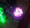
just hope this transformer will deliver 1000watts. Still disappointed with the size. I thought it would be bigger. Anywayz finger crossed
Registered Member #89
Joined: Thu Feb 09 2006, 02:40PM
Location: Zadar, Croatia
Posts: 3145
Hello -
I don't have much experience with paralleling mosfets in this circuit, but I fail to see the purpose of having portions of your tank capacitance across every mosfet. I would pretty definitely leave those out.
Also, there is no need for paralleling zeners, 10k resistors and diodes; you can use single zeners (of course with adequate power rating which you need to calculate according to your supply voltage). Also, single UF4007 diodes should be enough.
If you need to make up higher power zeners from several small ones, I recommend using a series of several lower voltage rated zeners. Paralleling diodes is generally a no-no and may result in explosions.
Finally, whenever you parallel mosfets it may be good idea to decouple mosfets from each other to prevent parasitic oscillations. A ferrite bead along with 10ohm resistor in series with each gate may be a good start. I think someone here even used steel nuts over the wires instead of ferrite beads for this purpose!
PS. I'm also seeing you intend to use ferrite cores for your inductors. In this case, make sure they are properly gapped so they can withstand the required currents without saturation. It would be wise to do some math on this as well before firing the oscillator up.
Registered Member #4254
Joined: Sat Dec 10 2011, 09:36PM
Location: Dhaka, Bangladesh
Posts: 27
Marko wrote ...
Hello -
I don't have much experience with paralleling mosfets in this circuit, but I fail to see the purpose of having portions of your tank capacitance across every mosfet. I would pretty definitely leave those out.
Also, there is no need for paralleling zeners, 10k resistors and diodes; you can use single zeners (of course with adequate power rating which you need to calculate according to your supply voltage). Also, single UF4007 diodes should be enough.
If you need to make up higher power zeners from several small ones, I recommend using a series of several lower voltage rated zeners. Paralleling diodes is generally a no-no and may result in explosions.
Finally, whenever you parallel mosfets it may be good idea to decouple mosfets from each other to prevent parasitic oscillations. A ferrite bead along with 10ohm resistor in series with each gate may be a good start. I think someone here even used steel nuts over the wires instead of ferrite beads for this purpose!
PS. I'm also seeing you intend to use ferrite cores for your inductors. In this case, make sure they are properly gapped so they can withstand the required currents without saturation. It would be wise to do some math on this as well before firing the oscillator up.
Marko
Hey thanks for the suggestions!
Those capacitors(snubber) were used to suppress high voltage spikes.
Anyways simpler is better. Revised schematic>>
each mosfet with 10 ohm resistor. I'll also use ferrite bead around each mosfet's gate. Any final tip????
This site is powered by e107, which is released under the GNU GPL License. All work on this site, except where otherwise noted, is licensed under a Creative Commons Attribution-ShareAlike 2.5 License. By submitting any information to this site, you agree that anything submitted will be so licensed. Please read our Disclaimer and Policies page for information on your rights and responsibilities regarding this site.


 Royer induction heater