If you need assistance, please send an email to forum at 4hv dot org. To ensure your email is not marked as spam, please include the phrase "4hv help" in the subject line. You can also find assistance via IRC, at irc.shadowworld.net, room #hvcomm.
Support 4hv.org!
Donate:
4hv.org is hosted on a dedicated server. Unfortunately, this server costs and we rely on the help of site members to keep 4hv.org running. Please consider donating. We will place your name on the thanks list and you'll be helping to keep 4hv.org alive and free for everyone. Members whose names appear in red bold have donated recently. Green bold denotes those who have recently donated to keep the server carbon neutral.
Special Thanks To:
Aaron Holmes
Aaron Wheeler
Adam Horden
Alan Scrimgeour
Andre
Andrew Haynes
Anonymous000
asabase
Austin Weil
barney
Barry
Bert Hickman
Bill Kukowski
Blitzorn
Brandon Paradelas
Bruce Bowling
BubeeMike
Byong Park
Cesiumsponge
Chris F.
Chris Hooper
Corey Worthington
Derek Woodroffe
Dalus
Dan Strother
Daniel Davis
Daniel Uhrenholt
datasheetarchive
Dave Billington
Dave Marshall
David F.
Dennis Rogers
drelectrix
Dr. John Gudenas
Dr. Spark
E.TexasTesla
eastvoltresearch
Eirik Taylor
Erik Dyakov
Erlend^SE
Finn Hammer
Firebug24k
GalliumMan
Gary Peterson
George Slade
GhostNull
Gordon Mcknight
Graham Armitage
Grant
GreySoul
Henry H
IamSmooth
In memory of Leo Powning
Jacob Cash
James Howells
James Pawson
Jeff Greenfield
Jeff Thomas
Jesse Frost
Jim Mitchell
jlr134
Joe Mastroianni
John Forcina
John Oberg
John Willcutt
Jon Newcomb
klugesmith
Leslie Wright
Lutz Hoffman
Mads Barnkob
Martin King
Mats Karlsson
Matt Gibson
Matthew Guidry
mbd
Michael D'Angelo
Mikkel
mileswaldron
mister_rf
Neil Foster
Nick de Smith
Nick Soroka
nicklenorp
Nik
Norman Stanley
Patrick Coleman
Paul Brodie
Paul Jordan
Paul Montgomery
Ped
Peter Krogen
Peter Terren
PhilGood
Richard Feldman
Robert Bush
Royce Bailey
Scott Fusare
Scott Newman
smiffy
Stella
Steven Busic
Steve Conner
Steve Jones
Steve Ward
Sulaiman
Thomas Coyle
Thomas A. Wallace
Thomas W
Timo
Torch
Ulf Jonsson
vasil
Vaxian
vladi mazzilli
wastehl
Weston
William Kim
William N.
William Stehl
Wesley Venis
The aforementioned have contributed financially to the continuing triumph of 4hv.org. They are deserving of my most heartfelt thanks.
Registered Member #205
Joined: Sat Feb 18 2006, 11:59AM
Location: Skørping, Denmark
Posts: 741
Steve Conner wrote ...
Hey Finn, just to say that Richie thinks you should lower your CCPS switching frequency to 20kHz. (ie, tune the resonant network to 40kHz) There is no single reason, except that it just "makes everything easier"
Tell Richie he is a mate!
Steve Conner wrote ...
I also heard that spikes of twice the DC bus voltage are par for the course with IGBT bricks, and the "cure" is to use bricks rated at more than twice the DC bus voltage.
Well, with the dead time I feel confident that I can keep the spikes below that, but it sure is a releif to know that it is the norm, and not just Murphy playing tricks with me.
Steve Conner wrote ...
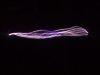
I used a choke-input filter with my Mazzilli PS, and I still get a nice sine wave under load.
I don`t know where I had my head when I made that scope shot, because this is what it looks like now.
Registered Member #205
Joined: Sat Feb 18 2006, 11:59AM
Location: Skørping, Denmark
Posts: 741
All, We have not given up completely at all, just like, you know, A guy`s gotta eat, so the day job thing..... Anyway, we have been working on getting a PCB manufacturing act together. We really need that ground plane on the controllers and stuff, so 2 sided photosensitive material formed the base for these 2 boards:
The board to the left is the voltage probe, and to the right is the controller board. It contains the 494 PWM oscillator which interfaces with the gate driver board trough dual UCC37xxx. Up front of it is a 74HC74 FF which takes care of synchronizing the start and stop of the pulse trains. Further up front is a LM339 quad comparator of which each of them can clamp the data pin low, for Voltage stop, Kill Switch stop, Over temp stop, and a delay stop, so that the charging starts a predetermined time after the tesla coil has rung down.
Speaking of the Gate driver. Now that the rest of the control circuitry is acquiring a half decent appearance, proper PCB`s and all, and since we are down to driving the gates right off the optocoupler anyway, the dinosaur beefy driver is going into the bin, and a nice PCB is being made for the gate driver as well. If the input to the beefy driver goes open, it settles into the high state, where all 4 IGBT`s are on, so we feel more comfortable with the opto`s which have to be forced to go high. We plan to lower the frequency as suggested by Richie Burnett, so they run quite cool, properly heatsunk. Sinked? Comments and suggestions are as always, very welcome.
Registered Member #205
Joined: Sat Feb 18 2006, 11:59AM
Location: Skørping, Denmark
Posts: 741
Wow, I sure had to look _way_ back to find an entry to this thread.
Most of the controll electronics into it`s 3rd iteration, and in compliance with current standards (Goldilock gate drive, etc. ) the transformer was next in line for a redesign.
We had listened to Richie at the Cambridge teslathon, and I had bought the book, Soft Ferrites by E. C. Snelling. Last weekend we made litz wire (16 strands of 0.25mm wire, 4 by 4) for the secondary, so now it was time for some kitchen table calculations:
Prior to Cambridge, we had based our transformer on the assumption, that core saturation was the sole limiting factor, when determining the amount volts per turn. Richie told us, that this is not always the case. After reading the Snelling book, and some of the excellent material at Magnetics website, It became clear that a soft ferrite core is saturation limited up to 20kHz. Beyond 20kHz, the core is loss limited, which means that the core gets too hot if it is driven all the way up to saturation.
Having a look at the loss curves for the material revealed that at 100kHz resonant frequency, the range from 100mW/cm^2 to 400mW/cm^2 corresponded to 100mT to 180mT We are of the opinion that an oil bath is a good thing, so operating the core at 300mW/cm^2 seemed allright. This means that the core should be driven up to ~160mT
I heard the moan! 100kHz? didn`t I tell you..... I know it is probably something we are going to regret, but at 100kHz resonant frequency, 50kHz swiching frequency, we are able to process all the power with just one core, so that is what we are going to try...
Putting this into the transformer equation: Npri=Upri/4*B*Amin*f Solves to 10 turns. We had 14 turns on the old transformers, so we expect to see some core temperature rise, as we now know is expected and desired. I had some copper foil left from a welding inverter that didn`t make it to the market:
And Daniel brought an Ø80mm bar of machining quality polypropylene, which was machined this weekend:
The resulting bobbins are here:
Each secondary section will see 5 layers of 4 turns, for a total of 8 centertapped kilovolts.
Well, that`s about it for now, from the path of an increadible learning experience. We are hell bent to make this thing work, and hopefully for more than just a millisecond, or so. As time will tell in its due course.
Registered Member #89
Joined: Thu Feb 09 2006, 02:40PM
Location: Zadar, Croatia
Posts: 3145
That is one pretty cool transformer finn - glad to see you being back to CCPS work :)
What did you use to carve the 'irregular' bobbin ends?
Prior to Cambridge, we had based our transformer on the assumption, that core saturation was the sole limiting factor, when determining the amount volts per turn. Richie told us, that this is not always the case. After reading the Snelling book, and some of the excellent material at Magnetics website, It became clear that a soft ferrite core is saturation limited up to 20kHz. Beyond 20kHz, the core is loss limited, which means that the core gets too hot if it is driven all the way up to saturation.
yes, that is an conclusion I came to too - when trying to puch large amounts of power through small cores I would be limited by heating far sooner than saturation.
No matter what frequency you use and not considering hysteresis losses, it simply seems to be eddy currents in the core - more V/turn you have, larger eddy currents and losses will be regardless of anything, you may have very low max flux density and still overheat the core. this was just my theory, though.
Other thing, I don't really know why cores heat so much if they get saturated - does hysteresis loss rapidly jump up there?
Registered Member #205
Joined: Sat Feb 18 2006, 11:59AM
Location: Skørping, Denmark
Posts: 741
Ultra7 wrote ...
not trying to sound stoopid, but whats CCPS stand for?
It means _C_apacitor _C_harging _P_ower _S_upply
It is built on the SLR topology. _S_eries _L_oad _R_esonant. The latter abbreviation should have been SRL in my opinion, but I was not around when it was coined.
Basically, it is a DRSSTC driver, only driven at a bit less than 1/2 the resonant frequency of the LC resonant load.
Ironically, this supply is going to power a T-BRISG, which will produce shorter sparks than could be acheived if we used the H-Bridge to drive the primary resonator directly.
Registered Member #152
Joined: Sun Feb 12 2006, 03:36PM
Location: Czech Rep.
Posts: 3384
I've read through the thread and I still don't understand one thing, why do I need to use 50% duty cycle on the gates? The free-wheeling current flows through the diode associated to to the same transistor that conducted the preceding halfwave right?
Registered Member #1232
Joined: Wed Jan 16 2008, 10:53PM
Location: Doon tha Toon!
Posts: 881
I've read through the thread and I still don't understand one thing, why do I need to use 50% duty cycle on the gates?
There is some latitude in the gate-drive timing to the switches in the SLR inverter because the actual "turn-off" instant of the device is dictated by the resonant frequency of the load - not the gate-drive signal. As long as the gate drive is on for at least half the resonant period, and not on longer than one whole resonant period it works. That makes overall duty ratio for each switch between 0.25 and 0.50 for correct operation.
If you think about it the IGBT's in an SLR inverter actually operate like thyristors: Once they're turned on, they stay on until the current changes direction. And indeed inverter grade thyristors are sometimes used in SLR systems.
The free-wheeling current flows through the diode associated to to the same transistor that conducted the preceding halfwave right?
Load current commutation sequence:
+ve load current forced down from V+ through channel of Q1 -ve load current freewheels up to V+ through D1 -ve load current forced down to V- through channel of Q2 +ve load current freewheels up from V- through D2
Registered Member #152
Joined: Sun Feb 12 2006, 03:36PM
Location: Czech Rep.
Posts: 3384
Ok, thanks.
I made a small scale "model" with a core from flyback xfmr, worked without problems. However it does not like open circuit loads (as was stated somewhere), the transistors get hot with no load. Any fix for this? Maybe to make the circuit self-tuning?
This site is powered by e107, which is released under the GNU GPL License. All work on this site, except where otherwise noted, is licensed under a Creative Commons Attribution-ShareAlike 2.5 License. By submitting any information to this site, you agree that anything submitted will be so licensed. Please read our Disclaimer and Policies page for information on your rights and responsibilities regarding this site.


 CCPS (Capacitor Charging Power Supply)


 ) the transformer was next in line for a redesign.