If you need assistance, please send an email to forum at 4hv dot org. To ensure your email is not marked as spam, please include the phrase "4hv help" in the subject line. You can also find assistance via IRC, at irc.shadowworld.net, room #hvcomm.
Support 4hv.org!
Donate:
4hv.org is hosted on a dedicated server. Unfortunately, this server costs and we rely on the help of site members to keep 4hv.org running. Please consider donating. We will place your name on the thanks list and you'll be helping to keep 4hv.org alive and free for everyone. Members whose names appear in red bold have donated recently. Green bold denotes those who have recently donated to keep the server carbon neutral.
Special Thanks To:
Aaron Holmes
Aaron Wheeler
Adam Horden
Alan Scrimgeour
Andre
Andrew Haynes
Anonymous000
asabase
Austin Weil
barney
Barry
Bert Hickman
Bill Kukowski
Blitzorn
Brandon Paradelas
Bruce Bowling
BubeeMike
Byong Park
Cesiumsponge
Chris F.
Chris Hooper
Corey Worthington
Derek Woodroffe
Dalus
Dan Strother
Daniel Davis
Daniel Uhrenholt
datasheetarchive
Dave Billington
Dave Marshall
David F.
Dennis Rogers
drelectrix
Dr. John Gudenas
Dr. Spark
E.TexasTesla
eastvoltresearch
Eirik Taylor
Erik Dyakov
Erlend^SE
Finn Hammer
Firebug24k
GalliumMan
Gary Peterson
George Slade
GhostNull
Gordon Mcknight
Graham Armitage
Grant
GreySoul
Henry H
IamSmooth
In memory of Leo Powning
Jacob Cash
James Howells
James Pawson
Jeff Greenfield
Jeff Thomas
Jesse Frost
Jim Mitchell
jlr134
Joe Mastroianni
John Forcina
John Oberg
John Willcutt
Jon Newcomb
klugesmith
Leslie Wright
Lutz Hoffman
Mads Barnkob
Martin King
Mats Karlsson
Matt Gibson
Matthew Guidry
mbd
Michael D'Angelo
Mikkel
mileswaldron
mister_rf
Neil Foster
Nick de Smith
Nick Soroka
nicklenorp
Nik
Norman Stanley
Patrick Coleman
Paul Brodie
Paul Jordan
Paul Montgomery
Ped
Peter Krogen
Peter Terren
PhilGood
Richard Feldman
Robert Bush
Royce Bailey
Scott Fusare
Scott Newman
smiffy
Stella
Steven Busic
Steve Conner
Steve Jones
Steve Ward
Sulaiman
Thomas Coyle
Thomas A. Wallace
Thomas W
Timo
Torch
Ulf Jonsson
vasil
Vaxian
vladi mazzilli
wastehl
Weston
William Kim
William N.
William Stehl
Wesley Venis
The aforementioned have contributed financially to the continuing triumph of 4hv.org. They are deserving of my most heartfelt thanks.
Registered Member #1232
Joined: Wed Jan 16 2008, 10:53PM
Location: Doon tha Toon!
Posts: 881
The problem with increasing the drive frequency to the NST is that the leakage inductance caused by the current shunts is going to result in a higher reactance at a higher frequency. So as you increase the frequency the available charging current will fall. e.g. At 240Hz, your 15kV/30mA NST becomes a 15kV/7.5mA transformer
Registered Member #543
Joined: Tue Feb 20 2007, 04:26PM
Location: UK
Posts: 4992
I must agree with everyone else it looks really cute, but I'm a little concerned about the seeming lack of anti-surge resistors in the circuit - once one element goes down it'll run a like a ladder in a stocking through the whole lot, as I'm sure many here will have found to their cost.
Registered Member #195
Joined: Fri Feb 17 2006, 08:27PM
Location: Berkeley, ca.
Posts: 1111
If you want more output you could use a flyback circuit witch runs at about 15khz at what ever voltage you need. If you want fullwave you would need two identical flyback transformers. a mazzilli circuit has the moast performance. hear is a link
Registered Member #1034
Joined: Sat Sept 29 2007, 12:50PM
Location: Chillicothe, Ohio
Posts: 154
I must agree with everyone else it looks really cute, but I'm a little concerned about the seeming lack of anti-surge resistors in the circuit - once one element goes down it'll run a like a ladder in a stocking through the whole lot, as I'm sure many here will have found to their cost.
That would be bad! The diodes in this thing where the biggest expense at $130.00 but so far I haven't had any problems.
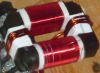
That's what gets me too. Maybe add an LED to the bottom to really Sci-Fi it up?
I thought about that too and I still might do it.
shouldn't hair present alot of charged points for corona losses?
That's a very interesting point. It turns out that her hair is an extremely poor conductor of electricity. Otherwise I think it would bleed the charge down a lot. I know that if I put a small brush made out of copper wire on the electrode it bleeds the charge down so much that I can only get about an inch of spark but you can really feel the charge in the air that some people describe as an "ion wind".
If you want more output you could use a flyback circuit witch runs at about 15khz
Thanks for the link. I might consider doing something like that some time.
Registered Member #543
Joined: Tue Feb 20 2007, 04:26PM
Location: UK
Posts: 4992
Hi Roger, as you are really only dealing in uA, the best retro-safeguard you can do is to increase the size of your output 'safety' resistor.
For a bigger splash, and so as not to undo all the hard work you have done, why not terminate your C&W with say 100M/75kV and use that to charge up a secondary capacitor, so if you have a dead short the storage, smoothing capoacitor will take the strain.
Obviously, asking direct sparks and arcs between HT+ and Earth will destroy almost any C&W given enough time, so you should always look to the needs of your application first, and then calculate all your component values after.
Registered Member #1034
Joined: Sat Sept 29 2007, 12:50PM
Location: Chillicothe, Ohio
Posts: 154
the best retro-safeguard you can do is to increase the size of your output 'safety' resistor.
I think the 1.5 mega ohms I have should be more than sufficient to protect the diodes. I'm guessing that the output voltage is about 100,000 volts so the max current would be about 66 ma. The diodes are rated for 100ma.
Registered Member #543
Joined: Tue Feb 20 2007, 04:26PM
Location: UK
Posts: 4992
RogerInOhio wrote ...
the best retro-safeguard you can do is to increase the size of your output 'safety' resistor.
I think the 1.5 mega ohms I have should be more than sufficient to protect the diodes. I'm guessing that the output voltage is about 100,000 volts so the max current would be about 66 ma. The diodes are rated for 100ma.
Have you tried running it under load continuously for 100 hours to see if you can get some empirical insights into the probable Mean Time Between Failures?
Don't me wrong, laddie, you've made a truly remarkable piece of kit there - the best looking C&W I've yet seen in my years at 4HV, and I'm sure all will second that. You've made something to be proud of.
But is there a possibility that while you've thought about shock loads on the output, what will happen if you get a really aggressive voltage spike coming in from the bottom?
I tried to make a simple analogy by talking of the way in which a ladder 'runs' in a pair of tights, but we could also think about it by saying that what is true for n is also true for n + 1, such that if you blow out a single diode the entire circuit will go down like a row of dominoes.
Registered Member #30
Joined: Fri Feb 03 2006, 10:52AM
Location: Glasgow, Scotland
Posts: 6706
Proud Mary wrote ...
I tried to make a simple analogy by talking of the way in which a ladder 'runs' in a pair of tights, but we could also think about it by saying that what is true for n is also true for n + 1
I like that! We should call it "destruction by induction".
The failure mode with CWs, as far as I know, is as follows:
An arc between the top of the stack and the bottom forms an LC resonant circuit, where C is the capacitor stack and L is the inductance of the arc and wiring. Because this inductance is low, the impedance of the circuit is low and the resonant frequency is high.
Before the arc, the energy is in the capacitor stack. The arc then kicks the circuit into resonance. One-quarter cycle later, the stack voltage is zero, and the energy that was in it is now in the stray inductance. Because of the low impedance and high initial voltage, the current corresponding to this stored energy could be hundreds, maybe thousands of amps.
The oscillation then continues, with this high current trying to recharge the capacitors in the opposite polarity. The diodes are taken out as they try to clamp this reverse voltage.
The cure of course, is to add enough resistance in series with the CW's output that the resulting RLC circuit is overdamped. It's then a mathematical certainty that the voltage will never reverse. The resistance must be rated to stand the CW's full output voltage without arcing over.
Registered Member #543
Joined: Tue Feb 20 2007, 04:26PM
Location: UK
Posts: 4992
Steve McConner wrote ...
Proud Mary wrote ...
I tried to make a simple analogy by talking of the way in which a ladder 'runs' in a pair of tights, but we could also think about it by saying that what is true for n is also true for n + 1, such that if you blow out a single diode the entire circuit will go down like a row of dominoes.
I like that! We should call it "destruction by induction".
The failure mode with CWs, as far as I know, is as follows:
An arc between the top of the stack and the bottom forms an LC resonant circuit, where C is the capacitor stack and L is the inductance of the arc and wiring. Because this inductance is low, the impedance of the circuit is low and the resonant frequency is high.
Before the arc, the energy is in the capacitor stack. The arc then kicks the circuit into resonance. One-quarter cycle later, the stack voltage is zero, and the energy that was in it is now in the stray inductance. Because of the low impedance and high initial voltage, the current corresponding to this stored energy could be hundreds, maybe thousands of amps.
The oscillation then continues, with this high current trying to recharge the capacitors in the opposite polarity. The diodes are taken out as they try to clamp this reverse voltage.
The cure of course, is to add enough resistance in series with the CW's output that the resulting RLC circuit is overdamped. It's then a mathematical certainty that the voltage will never reverse. The resistance must be rated to stand the CW's full output voltage without arcing over.
I don't disagree with your theoretical analysis in general, Steve, but even very careful drawing board designs, will defy expectations with that dreadful crack near the top of the stack which tells you your diodes are kaput. This is no very big deal when SF6 is used, apart from the cost of replacement parts, but if someone has taken the trouble to pot in epoxy or what have you, then they are uggered, and in for financial and emotional loss.
As we all know, C&Ws aren't pulse power devices, so I'd go for resistive damping in every stage in the hope (not certainty) of limiting spark over damage.
Reverting back to my original query on the adequacy of the 1M5 output resistor, I realise that I had not fully made myself clear. I'd agree with your 'adequate damping' analysis provided that the 1M5 resistor was correctly rated i.e. 1M5 141kV or what have you, because with no other damping in the circuit diagram as illustrated, a single output flashover would banjax the entire effort under what I'll call 'critical circumstances' - the electronic equivalent of a spring tide occurring together with a full moon and a gale driving it cumulative, and someone forgetting to take the bath plug out, and so on. You may say such an event is not likely to happen very often, but I'd say this lad has really put his heart into producing something special, and it would be uncharitable - false even - not to point out the vulnerabilities of the circuit as it is, whilst something can done to harden it up. Imagine if he was demonstrating it, as he surely will, and it all fizzled.
No doubt others will come forward to disagree, but I would always advise as good practice the de-rating of all C&W circuit elements by 66% at least for reliable continuous operation in SF6 or a good dielectric oil (dry kitchen- type sunflower) and by 80% or more in 'household' air.
I'd expect the output resistor to be a vitreous type rated at a notional 282kV (assuming Vout)max) is 100kV, (i.e. double PIV)
This site is powered by e107, which is released under the GNU GPL License. All work on this site, except where otherwise noted, is licensed under a Creative Commons Attribution-ShareAlike 2.5 License. By submitting any information to this site, you agree that anything submitted will be so licensed. Please read our Disclaimer and Policies page for information on your rights and responsibilities regarding this site.


 Full wave Cockcroft-Walton voltage multiplier