If you need assistance, please send an email to forum at 4hv dot org. To ensure your email is not marked as spam, please include the phrase "4hv help" in the subject line. You can also find assistance via IRC, at irc.shadowworld.net, room #hvcomm.
Support 4hv.org!
Donate:
4hv.org is hosted on a dedicated server. Unfortunately, this server costs and we rely on the help of site members to keep 4hv.org running. Please consider donating. We will place your name on the thanks list and you'll be helping to keep 4hv.org alive and free for everyone. Members whose names appear in red bold have donated recently. Green bold denotes those who have recently donated to keep the server carbon neutral.
Special Thanks To:
Aaron Holmes
Aaron Wheeler
Adam Horden
Alan Scrimgeour
Andre
Andrew Haynes
Anonymous000
asabase
Austin Weil
barney
Barry
Bert Hickman
Bill Kukowski
Blitzorn
Brandon Paradelas
Bruce Bowling
BubeeMike
Byong Park
Cesiumsponge
Chris F.
Chris Hooper
Corey Worthington
Derek Woodroffe
Dalus
Dan Strother
Daniel Davis
Daniel Uhrenholt
datasheetarchive
Dave Billington
Dave Marshall
David F.
Dennis Rogers
drelectrix
Dr. John Gudenas
Dr. Spark
E.TexasTesla
eastvoltresearch
Eirik Taylor
Erik Dyakov
Erlend^SE
Finn Hammer
Firebug24k
GalliumMan
Gary Peterson
George Slade
GhostNull
Gordon Mcknight
Graham Armitage
Grant
GreySoul
Henry H
IamSmooth
In memory of Leo Powning
Jacob Cash
James Howells
James Pawson
Jeff Greenfield
Jeff Thomas
Jesse Frost
Jim Mitchell
jlr134
Joe Mastroianni
John Forcina
John Oberg
John Willcutt
Jon Newcomb
klugesmith
Leslie Wright
Lutz Hoffman
Mads Barnkob
Martin King
Mats Karlsson
Matt Gibson
Matthew Guidry
mbd
Michael D'Angelo
Mikkel
mileswaldron
mister_rf
Neil Foster
Nick de Smith
Nick Soroka
nicklenorp
Nik
Norman Stanley
Patrick Coleman
Paul Brodie
Paul Jordan
Paul Montgomery
Ped
Peter Krogen
Peter Terren
PhilGood
Richard Feldman
Robert Bush
Royce Bailey
Scott Fusare
Scott Newman
smiffy
Stella
Steven Busic
Steve Conner
Steve Jones
Steve Ward
Sulaiman
Thomas Coyle
Thomas A. Wallace
Thomas W
Timo
Torch
Ulf Jonsson
vasil
Vaxian
vladi mazzilli
wastehl
Weston
William Kim
William N.
William Stehl
Wesley Venis
The aforementioned have contributed financially to the continuing triumph of 4hv.org. They are deserving of my most heartfelt thanks.
Registered Member #543
Joined: Tue Feb 20 2007, 04:26PM
Location: UK
Posts: 4992
803 wrote ...
Mary, the '01a is still here, you can buy it for $20. It's used in antique radios from the 20s and 30s. it's real name is the 201a
Oh, what makes you think that? I understood that 201-A was superceded by 01-A, but don't understand how RCA calling this valve "01-A" in their data sheet can not be 'real?'
01-A is first referenced in the Cunningham Radiotron RCA Manual 1934, Technical Series RC-12, p. 62.
Registered Member #1225
Joined: Sat Jan 12 2008, 01:24AM
Location: Beaumont, Texas, USA
Posts: 2253
I was actually just looking at the article you've posted, Proud Mary. It was much like that, though it was an actual Tesla coil, and alu foil on the outside rather than the foil and getter's capacitive coupling.
Though, i can definitely see why an internal target capacitive coupled to the supply would be best. I guess that is why the high freq from the Tesla coil was used.
edit: I tried to make some X rays with this magnetron and it did not seem to work. I covered the whole magnetron with a fort of MOTs for shielding and used a remote switch. I tried it with and without the heater, in both cases there was at least 60kv across the tube. I had it in an oil bath because the heater wires would arc over at around 20kv. The current was high, and pulsed, but obviously there was no need for it because even with the heater visibly on, it still had 60kv drop O_O.
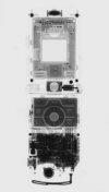
It is a working magnetron, magnets and fins removed. I used a couple HEI ignition coils in anti-series, and an SCR driver that charges a 20uf cap from the mains, and fired with a triac/diac combination. I used my camcorder to pick up any X-rays, as the X-rays would strike the CCD and light up a few pixels, like in this video of mine:
Also, a somewhat related question. Would X-rays make phosphor fluoresce?
Registered Member #543
Joined: Tue Feb 20 2007, 04:26PM
Location: UK
Posts: 4992
Arcstarter wrote ...
I was actually just looking at the article you've posted, Proud Mary. It was much like that, though it was an actual Tesla coil, and alu foil on the outside rather than the foil and getter's capacitive coupling.
Though, i can definitely see why an internal target capacitive coupled to the supply would be best. I guess that is why the high freq from the Tesla coil was used.
I believe that in the first year or two folllowing Roentgen's discovery of X-rays in 1895, that the rays were produced by the impact of electrons on the glass wall of Crookes' (tear-drop shaped) Tubes.
Registered Member #1134
Joined: Tue Nov 20 2007, 04:39PM
Location: Bonnie Scotland
Posts: 351
I once had access to 1800`s to 1900`s copies of Scientific American at the Library, and did quite a bit of research regarding x-rays in this period.
Very shortly after the initial discovery of x-rays, there were several articles printed, on the production of x-rays using available components, including carbon filament bulbs, of which the filament was connected to one pole of an induction coil, and the other pole of the induction coil was connected to a foil cap placed on the light bulb.
The first bulbs in case anyone was wondering, are a reasonably hard vacuum, and were not gas filled.
Sound familiar?
There was also printed in those early copies a veritable cookbook of homemade x-ray sensitive phosophors. I miss the old Sci-Am it was full of such wonderful practical science!
You do not necessarily have to use a Tesla/Oudin coil to capacitively couple through a glass envelope, however, as I recall a "coil producing a spark of not less than six inches" had to be used for these early experiments using induction coils, and lamps.
High Dv/Dt, is the most crucial factor in efficiently driving tubes in field emission mode, which is why flash driving works superbly, followed by Tesla/Oudin/Induction coil driving, with CW giving the poorest results.
Mary, the '01a is still here, you can buy it for $20. It's used in antique radios from the 20s and 30s. it's real name is the 201a
Oh, what makes you think that? I understood that 201-A was superceded by 01-A, but don't understand how RCA calling this valve "01-A" in their data sheet can not be 'real?'
01-A is first referenced in the Cunningham Radiotron RCA Manual 1934, Technical Series RC-12, p. 62.
well, you got me, I thought you ment the 201a as mostly, the 201a is mostly called the '01a. It still used the mag. getter, so I could still be right!.
Registered Member #1225
Joined: Sat Jan 12 2008, 01:24AM
Location: Beaumont, Texas, USA
Posts: 2253
I found a website that has something similar to the page i was describing, and similar to the page Proud Mary provided.
Notice, it is not grounded, the capacitance from plate to ground, i figure, is high enough. Or, maybe the capacitance from cathode to anode loosely couples them, and the capacitance from the internal parts to ground allows X-rays to be created.
Registered Member #543
Joined: Tue Feb 20 2007, 04:26PM
Location: UK
Posts: 4992
Arcstarter wrote ...
I found a website that has something similar to the page i was describing, and similar to the page Proud Mary provided.
Notice, it is not grounded, the capacitance from plate to ground, i figure, is high enough. Or, maybe the capacitance from cathode to anode loosely couples them, and the capacitance from the internal parts to ground allows X-rays to be created.
X-ray tubes (and valves tortured into producing X-rays! ) can be operated in three basic modes:*
1) Grounded anode - where the cathode/filament is at a high negative voltage, so the tube conducts only on the negative half cycle of an AC current as in the old Scientific American article. This method is often used in fixed (non-rotating) anode tubes with water cooling , because it enables the anode block and the cooling water supply to be held at ground potential while bolted to a metal structure or housing. This method has the disadvantage of needing a floating filament supply, in tubes using a thermionic cathode. (I use Hawker Cyclon lead-acid cells for this purpose)
2. Grounded cathode, where the anode is held at a high positive voltage. This method does not require an isolated floating filament supply, but makes conduction/water cooling of the anode block difficult.
3. Dual positive and negative supplies with a common Earth, which reduces insulation requirements, but otherwise has the diasvantages of the other two methods, with none of their advantages.
* Not including specialist flash X-ray tubes, whose mode of operation is rather different.
Registered Member #1225
Joined: Sat Jan 12 2008, 01:24AM
Location: Beaumont, Texas, USA
Posts: 2253
Proud Mary wrote ...
Arcstarter wrote ...
I found a website that has something similar to the page i was describing, and similar to the page Proud Mary provided.
Notice, it is not grounded, the capacitance from plate to ground, i figure, is high enough. Or, maybe the capacitance from cathode to anode loosely couples them, and the capacitance from the internal parts to ground allows X-rays to be created.
X-ray tubes (and valves tortured into producing X-rays! ) can be operated in three basic modes:*
1) Grounded anode - where the cathode/filament is at a high negative voltage, so the tube conducts only on the negative half cycle of an AC current as in the old Scientific American article. This method is often used in fixed (non-rotating) anode tubes with water cooling , because it enables the anode block and the cooling water supply to be held at ground potential while bolted to a metal structure or housing. This method has the disadvantage of needing a floating filament supply, in tubes using a thermionic cathode. (I use Hawker Cyclon lead-acid cells for this purpose)
2. Grounded cathode, where the anode is held at a high positive voltage. This method does not require an isolated floating filament supply, but makes conduction/water cooling of the anode block difficult.
3. Dual positive and negative supplies with a common Earth, which reduces insulation requirements, but otherwise has the diasvantages of the other two methods, with none of their advantages.
* Not including specialist flash X-ray tubes, whose mode of operation is rather different.
That's interesting. Do you mean flash X-ray tubes in general, or only specific kinds of flash X ray tubes? I know the basic theory of operation of flash X ray tubes.
I have a question about making a flash X ray device using an old electron tube rectifier, such as in Plasmatron's site ( ). He, and others, use a marx setup, or something else that provides a large current pulse.
Well, if you have no heater, which is suggested in his site, the voltage drop is very large. My ignition coils kept a voltage drop of around 60kv across my rectifier tube, even though low power. If using a 60kv marx, how would the tube draw any real current? Or, does it not draw much of any current? If i where to heat the filament, why would it produce less X-rays, provided the current from the marx/source was sufficient to sustain a high enough voltage drop?
Registered Member #543
Joined: Tue Feb 20 2007, 04:26PM
Location: UK
Posts: 4992
Arcstarter wrote ...
That's interesting. Do you mean flash X-ray tubes in general, or only specific kinds of flash X ray tubes? I know the basic theory of operation of flash X ray tubes.
I wish I did!
Arcstarter wrote ...
I have a question about making a flash X ray device using an old electron tube rectifier, such as in Plasmatron's site ( ). He, and others, use a marx setup, or something else that provides a large current pulse.
There is no need of Marx or other impulse generator to drive a flash X-ray tube. Simply discharging a capacitor through a tube of suitable geometry will initiate a vacuum breakdown discharge - the flash. See: Eur. Phys. J. Appl. Phys. 29, 91-97 (2005) DOI: 10.1051/epjap:2004176 X-rays emission from a compact diode energized by capacitor discharge M. Zakaullah1, S. Ahmed1, S. Hussain1, M. Afzal1 and A. Waheed2
1 Department of Physics, Quaid-i-Azam University, 45320 Islamabad, Pakistan 2 PINSTECH, PO Box 2151, 44000 Islamabad, Pakistan
Abstract X-ray emission from a compact diode consisting of a sharp edged cathode and flat anode of copper and lead, energized by simple capacitor discharge is reported. With a sewing machine needle cathode, and lead target, the generation efficiency upto 0.4% is obtained. The efficiency is expected to enhance further with the increase in discharge energy, charging voltage and reducing the parasitic inductance.
Just like a corona discharge in air, field emission is greatest where the electric field is most dense - at sharp points - so the finer the point the greater the field emission will be. This has lead in the last few years to the ultimate in fine points - the carbon nanotube - being used on the cathode of flash X-ray tubes. Such a concentration of field emission together with a sufficient potential difference leads to vacuum breakdown, and a fast current pulse - which is why it is important to have circuit inductance as low as possible, since inductance would slow the pulse down.
The exact nature of 'vacuum breakdown' is still being heavily researched, but suffice it to say it contains elements of spark, arc, and probably quantum tunneling, so I shan't try to explain what I don't myself fully understand.
Arcstarter wrote ...
Well, if you have no heater, which is suggested in his site, the voltage drop is very large. My ignition coils kept a voltage drop of around 60kv across my rectifier tube, even though low power. If using a 60kv marx, how would the tube draw any real current? Or, does it not draw much of any current? If i where to heat the filament, why would it produce less X-rays, provided the current from the marx/source was sufficient to sustain a high enough voltage drop?
Let us take the case of a simple thermionic diode rectifier of the type which was used many years ago to rectify the CRT high voltage supply in a TV. In normal operation, with the heater boiling electrons off the cathode, the voltage drop across the diode will be 150V or so, and with such a low potential difference between anode and cathode, no X-rays that can get through the glass wall of the tube will be produced. Now, if the heater fails, the valve will(almost!) stop conducting, and the potential difference across it will rise to the full value of the supply - say 20kV. Now this is enough to cause field emission to break out from sharp edges and points, and the freed electrons will be accelerated towards the anode. Some of the electrons impacting on the anode will produce X-rays, with a small percentage of them having a maximum photon energy of 20keV - the same as the supply voltage.
While the diode may pass a current of say 1.5mA with the heater running in normal operation, it may only pass 30 or 40uA due to field emission, but these electrons, accelerated by the large voltage drop across the valve will produce some X-rays. This was the mode of X-ray production used in cold cathode tubes before the invention of the Coolidge tube (1917) which has a heated cathode.
Flash X-ray mode is more dependent on electrode geometry - the needle cathode and the flat plate anode to enable vacuum breakdown - than it is on anode voltage alone. With a tube of suitable geometry, flash X-ray vacuum breakdown will occur simply by discharging a single low inductance HV capacitor through the tube.
Afterword: The case of X-ray production by colour TV EHT shunt stabiliser triodes - thermionic valves configured to work much like zener diodes acros the HV supply - is rather different to most other cases of X-ray producing valves, in that they produced X-rays during normal operation.
Triodes like 6BK4B and PD500 worked with ~25kV on the anode in typical operation, which was sufficient to generate X-rays capable of penetrating the glass bulb - the media discovery of which lead to alarm and scandal in the 1960s, some of it justified.
This lead to the hasty production of a less hazardous successor to 6BK4B - 6BK4C - which used lead glass, and carried an X-ray hazard warning in the datasheet together with a statement that the valve would not generate more than 1.5mR/hr.
Both 6BK4B and PD500 have formed the basis of many amateur X-ray setups, most often using them in cold cathode mode, where the experimenters have not been able to access or afford dedicated X-ray technology. Needless to say, the absence of a defined focal spot has meant that the images produced are not of the first quality.
Registered Member #1134
Joined: Tue Nov 20 2007, 04:39PM
Location: Bonnie Scotland
Posts: 351
Arcstarter wrote ...
If using a 60kv marx, how would the tube draw any real current? Or, does it not draw much of any current? If i where to heat the filament, why would it produce less X-rays, provided the current from the marx/source was sufficient to sustain a high enough voltage drop?
When driving a tube in "flash mode", either by using a Marx/Spiral generator/LC inversion circuit, the current drawn by the tube is in fact huge.
During the impulse, field emission occurs explosively at the cathode, leading to vacuum plasma formation. During the short period of plasma formation, thousands of amps can flow.
The exact cause is still a bit of a mystery as Proud Mary said. Even the standard models for ordinary field emission are highly complex and only recently a decent mathematical model was put forth that could explain the goings on at the tip of a single fine point!
This site is powered by e107, which is released under the GNU GPL License. All work on this site, except where otherwise noted, is licensed under a Creative Commons Attribution-ShareAlike 2.5 License. By submitting any information to this site, you agree that anything submitted will be so licensed. Please read our Disclaimer and Policies page for information on your rights and responsibilities regarding this site.


 X-Ray VS Magnetron?