If you need assistance, please send an email to forum at 4hv dot org. To ensure your email is not marked as spam, please include the phrase "4hv help" in the subject line. You can also find assistance via IRC, at irc.shadowworld.net, room #hvcomm.
Support 4hv.org!
Donate:
4hv.org is hosted on a dedicated server. Unfortunately, this server costs and we rely on the help of site members to keep 4hv.org running. Please consider donating. We will place your name on the thanks list and you'll be helping to keep 4hv.org alive and free for everyone. Members whose names appear in red bold have donated recently. Green bold denotes those who have recently donated to keep the server carbon neutral.
Special Thanks To:
Aaron Holmes
Aaron Wheeler
Adam Horden
Alan Scrimgeour
Andre
Andrew Haynes
Anonymous000
asabase
Austin Weil
barney
Barry
Bert Hickman
Bill Kukowski
Blitzorn
Brandon Paradelas
Bruce Bowling
BubeeMike
Byong Park
Cesiumsponge
Chris F.
Chris Hooper
Corey Worthington
Derek Woodroffe
Dalus
Dan Strother
Daniel Davis
Daniel Uhrenholt
datasheetarchive
Dave Billington
Dave Marshall
David F.
Dennis Rogers
drelectrix
Dr. John Gudenas
Dr. Spark
E.TexasTesla
eastvoltresearch
Eirik Taylor
Erik Dyakov
Erlend^SE
Finn Hammer
Firebug24k
GalliumMan
Gary Peterson
George Slade
GhostNull
Gordon Mcknight
Graham Armitage
Grant
GreySoul
Henry H
IamSmooth
In memory of Leo Powning
Jacob Cash
James Howells
James Pawson
Jeff Greenfield
Jeff Thomas
Jesse Frost
Jim Mitchell
jlr134
Joe Mastroianni
John Forcina
John Oberg
John Willcutt
Jon Newcomb
klugesmith
Leslie Wright
Lutz Hoffman
Mads Barnkob
Martin King
Mats Karlsson
Matt Gibson
Matthew Guidry
mbd
Michael D'Angelo
Mikkel
mileswaldron
mister_rf
Neil Foster
Nick de Smith
Nick Soroka
nicklenorp
Nik
Norman Stanley
Patrick Coleman
Paul Brodie
Paul Jordan
Paul Montgomery
Ped
Peter Krogen
Peter Terren
PhilGood
Richard Feldman
Robert Bush
Royce Bailey
Scott Fusare
Scott Newman
smiffy
Stella
Steven Busic
Steve Conner
Steve Jones
Steve Ward
Sulaiman
Thomas Coyle
Thomas A. Wallace
Thomas W
Timo
Torch
Ulf Jonsson
vasil
Vaxian
vladi mazzilli
wastehl
Weston
William Kim
William N.
William Stehl
Wesley Venis
The aforementioned have contributed financially to the continuing triumph of 4hv.org. They are deserving of my most heartfelt thanks.
Registered Member #249
Joined: Fri Feb 24 2006, 05:45PM
Location:
Posts: 2
Hey all, To be precise, this will be my first post however I have been actively reading these forums for little over a year now. I figured for those of you interested in projects such as a plasma globe, this information would be quite usefull. While there is no clean and easy way, here is a method you can use to disable the rectifier in most modern flybacks:
There are two ways to bypass the diodes. Both are a pain.
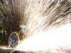
1) See attached picture. If you grind away the housing with a drum sander or belt sander, you can get down to the diodes and solder wires across them. The dust is atrocious, use a mask or respirator. In the picture, from the left, the first unit is a typical flyback. The 2nd is bypassed with an epoxy coating over the diodes and wires. You can see the diodes and wires in the picture. Only about half of each diode is left because it has been sanded away. The other two are bypassed and coated with high voltage dope so you can’t see much.
2) The other way to bypass is to drive a high voltage/high current across the diodes and permanently short them. I have succeeded in doing this with a microwave oven transformer. Unfortunately, I have not been able to develop a sure fire scientific method to accomplish it. If the HV current is maintained for too long the flyback overheats and cracks the housing. So far I only created two good flybacks this way and destroyed twelve. I had hoped to better define this process before posting it.
To drive the flyback I have been using a ferrite toroid with an approximately 90 turn secondary connected to the flyback primary. I use 5 or 6 turns for the toroid primary connected to the base of the transistor and 1 or 2 turns for the feedback connected to the transistor gate. I have used both 2N3055 and MJ15003 transistors.
In order to keep credit where credit is due, all information posted was provided by the rather clever Mark Dunn of
Registered Member #91
Joined: Thu Feb 09 2006, 03:03PM
Location: The Netherlands
Posts: 45
Looks cool indeed, I'm going to see if I can sand off one of my flybacks too and see if I can bypass the diode.
Attached picture shows the victim; I'm guessing that the rectifier sits inside the area within the red circle (judging by the pictures in the first post). I already sanded off a very small part to see how that worked out.
Registered Member #249
Joined: Fri Feb 24 2006, 05:45PM
Location:
Posts: 2
Not Quite Kipmans, but your on the right track. The rectifier is under the twisty knobs encased in a box of that yellow goo. Once you grind past the twisty knobbs be carefull because the diode itself is not far behind it. The last transformer I did this to came from Electronic goldmine and only had 1 single diode and a couple of capacitors. I'd have a nice closeup of it however I have left my camera with the gf... damn
Here is the previous picture zoomed with the area to grind marked.
Registered Member #102
Joined: Thu Feb 09 2006, 08:15PM
Location: Raleigh, NC
Posts: 169
Of course, this is completely off toppic. But hey, you seem to like destroying things Me too! What all is in one of those flybacks? I get the basic idea of whats in there, though I'm wondering where they are placed in the device. It should be considered that not all flybacks have those "twisty knobs" where do i look for the diode(s) in one w/o?
Registered Member #79
Joined: Thu Feb 09 2006, 11:35AM
Location: Arkansas
Posts: 673
I haven't seen a modern FBT without twisty knobs... To find out what all is in a FBT, there's schematics for them on the net, there was also a thread on this in the old forum.
Registered Member #188
Joined: Thu Feb 16 2006, 05:18PM
Location:
Posts: 67
I recently opened up a broken LOPT with a chisel. I could extract (all of it damaged): -7 diodes (about 1,5cm long 4mm thick) 1 capacitor about 4cm long, 1cm thick and 2.5cm wide 1 capacitor 3cm long, 0,75cm thick and 1.5cm wide 2 high value resistors (zigzag trrack glazed on ceramic) the focus divider assembly
This site is powered by e107, which is released under the GNU GPL License. All work on this site, except where otherwise noted, is licensed under a Creative Commons Attribution-ShareAlike 2.5 License. By submitting any information to this site, you agree that anything submitted will be so licensed. Please read our Disclaimer and Policies page for information on your rights and responsibilities regarding this site.


 Disabling rectifier in most flybacks