If you need assistance, please send an email to forum at 4hv dot org. To ensure your email is not marked as spam, please include the phrase "4hv help" in the subject line. You can also find assistance via IRC, at irc.shadowworld.net, room #hvcomm.
Support 4hv.org!
Donate:
4hv.org is hosted on a dedicated server. Unfortunately, this server costs and we rely on the help of site members to keep 4hv.org running. Please consider donating. We will place your name on the thanks list and you'll be helping to keep 4hv.org alive and free for everyone. Members whose names appear in red bold have donated recently. Green bold denotes those who have recently donated to keep the server carbon neutral.
Special Thanks To:
Aaron Holmes
Aaron Wheeler
Adam Horden
Alan Scrimgeour
Andre
Andrew Haynes
Anonymous000
asabase
Austin Weil
barney
Barry
Bert Hickman
Bill Kukowski
Blitzorn
Brandon Paradelas
Bruce Bowling
BubeeMike
Byong Park
Cesiumsponge
Chris F.
Chris Hooper
Corey Worthington
Derek Woodroffe
Dalus
Dan Strother
Daniel Davis
Daniel Uhrenholt
datasheetarchive
Dave Billington
Dave Marshall
David F.
Dennis Rogers
drelectrix
Dr. John Gudenas
Dr. Spark
E.TexasTesla
eastvoltresearch
Eirik Taylor
Erik Dyakov
Erlend^SE
Finn Hammer
Firebug24k
GalliumMan
Gary Peterson
George Slade
GhostNull
Gordon Mcknight
Graham Armitage
Grant
GreySoul
Henry H
IamSmooth
In memory of Leo Powning
Jacob Cash
James Howells
James Pawson
Jeff Greenfield
Jeff Thomas
Jesse Frost
Jim Mitchell
jlr134
Joe Mastroianni
John Forcina
John Oberg
John Willcutt
Jon Newcomb
klugesmith
Leslie Wright
Lutz Hoffman
Mads Barnkob
Martin King
Mats Karlsson
Matt Gibson
Matthew Guidry
mbd
Michael D'Angelo
Mikkel
mileswaldron
mister_rf
Neil Foster
Nick de Smith
Nick Soroka
nicklenorp
Nik
Norman Stanley
Patrick Coleman
Paul Brodie
Paul Jordan
Paul Montgomery
Ped
Peter Krogen
Peter Terren
PhilGood
Richard Feldman
Robert Bush
Royce Bailey
Scott Fusare
Scott Newman
smiffy
Stella
Steven Busic
Steve Conner
Steve Jones
Steve Ward
Sulaiman
Thomas Coyle
Thomas A. Wallace
Thomas W
Timo
Torch
Ulf Jonsson
vasil
Vaxian
vladi mazzilli
wastehl
Weston
William Kim
William N.
William Stehl
Wesley Venis
The aforementioned have contributed financially to the continuing triumph of 4hv.org. They are deserving of my most heartfelt thanks.
Registered Member #528
Joined: Fri Feb 16 2007, 10:32PM
Location: Warsaw, Poland
Posts: 166
Goddamn, I finally got forum account. A few months ago I tried to get it and sent a few mails, but without responses. Today I've noticed registration is enabled, so, not to loose ocassion, I registered at last.
First, hello to you all. My name is Michal (in english Michael, spanish Miguel ), I'm 19 years old passional guy. I've been playing with variables things, but rather two of them are noteworthy - pumping last droplets from PC perfomance via overclocking, voltage modifications and etc., however it's rather a history. Three years ago I had been sucked in refrigeration, espacieally in low temperature, that's what I was doing for two years. But, becasue of costs I could barely finish projects, so.. I've lured into internet and found accidently a polish forum, where HV things were described. It caught my attention and was looking interesting, so.. a HV passion has begun. I will tell in a shortcuit what I've done (chronologicaly).
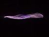
The first working TV transformer driver was based on one transistor, 2N3055. I had a lot problems at begin, since I didn't even know how transistors work, but at last I've managed it to work. The spark was thiny and only 1cm, but this time I was really happy, it looked so amazingly for me. There are samples of this spark :
In meantime, I got a better power supply made by 100W transformer, rectify bridge and a few capacitors. The results were more impressive, but, of course, not enough for my increasing hungry of sparks! :P
The next step was about bulbs. With 2N3055 driver and one electrode connected to bulb's screw and bottom, the sparks were hardly visible. So, I plugged second electrode to wire, which was bended on buld. Sparks became looking more neat. There are pics :
Later, I bought a TV cascade which multipled voltage a lot and I started to feel fear. Instead of 1cm spark, I've achieved 8cm length one.
On right side, a TV cascade is shown
Unfortunately, I don't have a picture of 8cm spark, but it doesn't look a lot different from 1cm one.
Then, I plugged a bulb and that was the my best success, since it does look really marvelous for me :
Before :
After :
The next step was ZVS driver. A lot of time passed before I got this driver to work. There's photo of elements :
First revision of ZVS, which didn't work :
Testing :
The problem was caused by unproper connecting fast diodes's outputs. At this time I didn't know if it does make difference, so I've decided to make a first home made PCB and do it a bit more professional :
The entire setup :
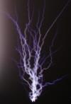
It finally worked. A nice, fire-like, fatty and white spark that can be stretched a lot.
Picture of spark :
From this time I started to weak driver. I've made another PCB :
Next, I put two primary windings on one ferrite core and connected them in series. That theoretically doubled output voltage, in practice it made spark a bit thinner but a lot longer. There are last pics of spark that I have on disk :
This revision gave a spar that could be stretched to about 7cm. After last tweaking, I was able to get 10cm ;) But there I have a question, from what a output voltage/current ratio depends? Is there a way to set ZVS in way that it would produce more voltage and less current?
Now, I'm trying to learn about halfbridge and fullbridges, since I didn't find another simple driver more powerful than ZVS. From what I know, a half bridge with two transistors steered by a chip (example, IR2153) that makes switching transistors gates in first-second-first-second etc. way, sounds a good candidate for me, especially when I have some of parts. But I can't find basic informations, how a halfbridge works, what's are the most important elements, etc. Would anyone give any interesting links about it?
Registered Member #95
Joined: Thu Feb 09 2006, 04:57PM
Location: Norway
Posts: 1308
Welcome to 4HV, sorry to hear you couldn't register sooner. You've sure been busy, and taken some great pictures too, its good to see another new member here.
For the ZVS driver you can change the frequency and voltage by playing with different capacitor and inductor values. (Are you using the mazzilli driver?) I haven't used my ZVS driver for over a year so I can't offer any more advice. Other members here have tweaked the mazzilli driver pretty far though.
About half-bridges and such, check out our HvWiki, and NEETS There should be some stuff on half-bridges there. Basically a half bridge switches the current in two directions, making a true AC signal. It works by using a capacitor divider to make an artificial ground, which the switches dump power into. The switches are never on at the same time.
Registered Member #528
Joined: Fri Feb 16 2007, 10:32PM
Location: Warsaw, Poland
Posts: 166
wrote ...
About half-bridges and such, check out our HvWiki, and NEETS There should be some stuff on half-bridges there. Basically a half bridge switches the current in two directions, making a true AC signal. It works by using a capacitor divider to make an artificial ground, which the switches dump power into. The switches are never on at the same time.
And thanks to two transistors, a primary winding's current flows in opposite ways xx-xxx kHz times in second? The larger frequency is, a higher voltage output is (if I remember correctly first Faraday's law and according to this, higher frequency creates more magnetic field's stream changes, which cause higher inducted voltage in secondary winding)?
wrote ...
For the ZVS driver you can change the frequency and voltage by playing with different capacitor and inductor values. (Are you using the mazzilli driver?) I haven't used my ZVS driver for over a year so I can't offer any more advice. Other members here have tweaked the mazzilli driver pretty far though.
Yes, this is Mazilli's driver. The another trick I should play with is decreasing primary turns in order to obtain higher secondary/primary ratio (how it is called in english?) and output voltage. But it would also decrease primary's resistance and MOSFETs would get hotter.
Hm, I've reminded my actual problem with primary windings. Before anything the whole setup was working greatly - nothing was heating, MOSFETs were barely warm (those are IRFP250), inductor was moderately heated. But after playing with parts, it changed - primary winding started to act as indution heating, heating ferrite core to very high temperature that my finger can't stand. And I've broken in that way two parts of ferrite core, which were surprisingly fragile at high temperature. Despite this heating problem, I can have flame spark, as before. I have no idea what I've done with it. Winding seems to be made correctly, I don't see short-circuits, nothing looking suspicious. I thought it might be caused by wire - it's ~0.5-07mm and at full load driver pumps from PSU somethign around 10-11A. Maybe this wire is too thin? Has anyone a table, where different thicnkess of wire and their max working current are shown?
Registered Member #95
Joined: Thu Feb 09 2006, 04:57PM
Location: Norway
Posts: 1308
Tonic wrote ...
And thanks to two transistors, a primary winding's current flows in opposite ways xx-xxx kHz times in second? The larger frequency is, a higher voltage output is (if I remember correctly first Faraday's law and according to this, higher frequency creates more magnetic field's stream changes, which cause higher inducted voltage in secondary winding)?
Jepp.
Here is a table with everything you need to know about wire. Lots of people have had their primaries almost melt with the mazzilli driver, but as said I've never run it over 12 volts, so I've never had such a problem. However one of the other members can help you with the mazzilli driver, I don't even know how it works.
Registered Member #56
Joined: Thu Feb 09 2006, 05:02AM
Location: Southern Califorina, USA
Posts: 2445
that table is useless for anything that runs at >100hz, as then you have to deal with the skin effect. I was using a 10awg stranded primary on my driver running at 750w of power, and it lasted about 2 minutes before it started to smoke.
Registered Member #89
Joined: Thu Feb 09 2006, 02:40PM
Location: Zadar, Croatia
Posts: 3145
Hi Michal
You can strand a bunch of enamelled wires for your primary coil if skin effect really troubles you.
Anyway, at over 100kHz, you should be able to push over a kilowatt of power through an average flyback core, enough to destroy most TV flybacks. Core loss also increases heavily with increase of frequency.
To increase output power it's usually enough just to reduce number of primary turns. Just increasing the frequency will actually lower your output power unless you simultaneously decrease number of your primary turns.
It's actually best for the core if you run it close to saturation at lowest frequency possible.
Registered Member #528
Joined: Fri Feb 16 2007, 10:32PM
Location: Warsaw, Poland
Posts: 166
Well, I digged a bit there and found a few interesting ideas that I want to try ;) These are : capacitors on driver's input, larger radiators, places on PCB for few resonating capacitor (MMC array, in that way I can play with frequency and worry less about heating), second primary coil, as Andrineri done or suggested, separate gate supply etc. In that way that would be a configurable driver, for example, I would replace MOSFETs to IGBTs and try to plug ZVS into main ;)
wrote ...
You can strand a bunch of enamelled wires for your primary coil if skin effect really troubles you.
So, is it a skin effect that causes heating? And why strand instead of fatter wire?
wrote ...
Anyway, at over 100kHz, you should be able to push over a kilowatt of power through an average flyback core, enough to destroy most TV flybacks. Core loss also increases heavily with increase of frequency.
Mechanical vibrations?
wrote ...
It's actually best for the core if you run it close to saturation at lowest frequency possible.
Whoa, please, don't make my eyes wanting to jump out Saturation.. that's the term I must learn.
Registered Member #192
Joined: Fri Feb 17 2006, 03:08AM
Location: Canada
Posts: 44
Tonic,
Another suggetion that I was given to increase output was to replace the 12 Volt zeners with 15 or 18 volt ones. I'm using 15 volt zeners now. Also a 0.68uF cap across the center tap of your flyback and ground. Some members dissagree with this one though it does increase output. I'm using 3 SLA batteries for 36 volt operation and it just sizzles. Next I'll have to try lowering the primary turns to 4 and 4 and try the second primary too.
Registered Member #528
Joined: Fri Feb 16 2007, 10:32PM
Location: Warsaw, Poland
Posts: 166
wrote ...
Another suggetion that I was given to increase output was to replace the 12 Volt zeners with 15 or 18 volt ones. I'm using 15 volt zeners now.
Sounds that you tried a few Zeners diodes, if yes, did you notice any differents?
wrote ...
Also a 0.68uF cap across the center tap of your flyback and ground. Some members dissagree with this one though it does increase output. I'm using 3 SLA batteries for 36 volt operation and it just sizzles. Next I'll have to try lowering the primary turns to 4 and 4 and try the second primary too.
One capacitor's leg to center tap and second leg to ground? I've never heard of it. But thanks, it wouldn't be a problem to check, if there's a difference.
Although, I have problem with getting higher input voltages than 24V. I'm using 100W transformer 230V->24V AC, after adding rectify bridge and capacitors, it gives something around 35V without load. By the way, why more? I thought if AC and DC give the same power, DC has lower voltage.. Vmax/sqrt(2) minus the voltage drop that occurs in rectify bridge. I must try to get power supply that will give more voltage, since I do actually prefer to see longer and purplish arcs. Flame arcs bored me ;P I thought about voltage doubler or tripler, but I saw a few types of them and I don't know what diodes and capacitors parameters are workable - on www pages I've found only theory, no practical advices that would suit my taste. I want to get higher voltage in simple and cheap way. If anyone can help with it, I would really appreciate it. Since IRFP250s can work at 200V, a 50 DCV would be a great option, knowing that there might be voltage spikes four time higher that input voltage (4x50V=200V and it doesn't get over max IRFP250 operating voltage).
This site is powered by e107, which is released under the GNU GPL License. All work on this site, except where otherwise noted, is licensed under a Creative Commons Attribution-ShareAlike 2.5 License. By submitting any information to this site, you agree that anything submitted will be so licensed. Please read our Disclaimer and Policies page for information on your rights and responsibilities regarding this site.


 New fresh meat's toys and questions

 ), I'm 19 years old passional guy. I've been playing with variables things, but rather two of them are noteworthy - pumping last droplets from PC perfomance via overclocking, voltage modifications and etc., however it's rather a history. Three years ago I had been sucked in refrigeration, espacieally in low temperature, that's what I was doing for two years. But, becasue of costs I could barely finish projects, so.. I've lured into internet and found accidently a polish forum, where HV things were described. It caught my attention and was looking interesting, so.. a HV passion has begun. I will tell in a shortcuit what I've done (chronologicaly).