If you need assistance, please send an email to forum at 4hv dot org. To ensure your email is not marked as spam, please include the phrase "4hv help" in the subject line. You can also find assistance via IRC, at irc.shadowworld.net, room #hvcomm.
Support 4hv.org!
Donate:
4hv.org is hosted on a dedicated server. Unfortunately, this server costs and we rely on the help of site members to keep 4hv.org running. Please consider donating. We will place your name on the thanks list and you'll be helping to keep 4hv.org alive and free for everyone. Members whose names appear in red bold have donated recently. Green bold denotes those who have recently donated to keep the server carbon neutral.
Special Thanks To:
Aaron Holmes
Aaron Wheeler
Adam Horden
Alan Scrimgeour
Andre
Andrew Haynes
Anonymous000
asabase
Austin Weil
barney
Barry
Bert Hickman
Bill Kukowski
Blitzorn
Brandon Paradelas
Bruce Bowling
BubeeMike
Byong Park
Cesiumsponge
Chris F.
Chris Hooper
Corey Worthington
Derek Woodroffe
Dalus
Dan Strother
Daniel Davis
Daniel Uhrenholt
datasheetarchive
Dave Billington
Dave Marshall
David F.
Dennis Rogers
drelectrix
Dr. John Gudenas
Dr. Spark
E.TexasTesla
eastvoltresearch
Eirik Taylor
Erik Dyakov
Erlend^SE
Finn Hammer
Firebug24k
GalliumMan
Gary Peterson
George Slade
GhostNull
Gordon Mcknight
Graham Armitage
Grant
GreySoul
Henry H
IamSmooth
In memory of Leo Powning
Jacob Cash
James Howells
James Pawson
Jeff Greenfield
Jeff Thomas
Jesse Frost
Jim Mitchell
jlr134
Joe Mastroianni
John Forcina
John Oberg
John Willcutt
Jon Newcomb
klugesmith
Leslie Wright
Lutz Hoffman
Mads Barnkob
Martin King
Mats Karlsson
Matt Gibson
Matthew Guidry
mbd
Michael D'Angelo
Mikkel
mileswaldron
mister_rf
Neil Foster
Nick de Smith
Nick Soroka
nicklenorp
Nik
Norman Stanley
Patrick Coleman
Paul Brodie
Paul Jordan
Paul Montgomery
Ped
Peter Krogen
Peter Terren
PhilGood
Richard Feldman
Robert Bush
Royce Bailey
Scott Fusare
Scott Newman
smiffy
Stella
Steven Busic
Steve Conner
Steve Jones
Steve Ward
Sulaiman
Thomas Coyle
Thomas A. Wallace
Thomas W
Timo
Torch
Ulf Jonsson
vasil
Vaxian
vladi mazzilli
wastehl
Weston
William Kim
William N.
William Stehl
Wesley Venis
The aforementioned have contributed financially to the continuing triumph of 4hv.org. They are deserving of my most heartfelt thanks.
Registered Member #580
Joined: Mon Mar 12 2007, 03:17PM
Location: Melbourne, Australia
Posts: 410
Does anyone know of a galvanically isolated technique for measuring the primary current of a DRSSTC, that is phase accurate? It must: work up to 1MHz, support isolation voltages seen in a DRSSTC, support currents seen in a DRSSTC. The amplitude is not very relevant, this will just be to feed into a zero current detector circuit.
Registered Member #11591
Joined: Wed Mar 20 2013, 08:20PM
Location: UK
Posts: 556
There is one series of IC that will do it: the allegro acs732 series. Bandwidth of 1 MHz, only problem is the current rating, which is 40 A bidirectionally; a little low. A current transformer will do fine though, it fits every requirement and can even be made pretty easily, just don't forget a burden resistor to convert the current to a voltage!
Registered Member #2099
Joined: Wed Apr 29 2009, 12:22AM
Location: Los Altos, California
Posts: 1714
Hen's current transformer suggestion sounds good to me. There are ferrite core materials with high permeability and low loss up to hundreds of MHz, e.g. in baluns. One might explore Rogowski coils, if no suitable ferrite core is on hand, but I think they are not trivial at high frequencies.
Since you only care about zero crossings, the burden on CT secondary could be two diodes in "antiparallel". How about a single Zener diode instead, to simplify digital logic level shifting?
That Allegro series current sensor could probably have its range extended with appropriate external shunt resistor (mind the inductances). Or use several identical devices in parallel, and combine their outputs. I bet it's based on Hall effect. What's the time delay corresponding to its 1 MHz bandwidth rating, and does the bandwidth vary widely with process and temperature?
If both ends of DRSSTC primary are "hot", voltage wise, consider electrostatic shielding in or around the current sensor.
Why is zero current a time of interest in a DRSSTC? Just curious.
Registered Member #580
Joined: Mon Mar 12 2007, 03:17PM
Location: Melbourne, Australia
Posts: 410
wrote ...
Why is zero current a time of interest in a DRSSTC? Just curious.
as Uspring said, it is best (for the semiconductors) for the interrupt turn off to be delayed until there is 0 current going through the primary
wrote ...
current transformer
here is a comparison of a non isolated resistive bridge (top waveform), vs a current transformer (bottom waveform) you can see the ~90 degree phase shift
wrote ...
That Allegro series current sensor could probably have its range extended with appropriate external shunt resistor
Interesting! unfortunately without a DSO I have no idea what sort of peak currents are involved to calculate the shunt (when run from 330v rectified mains)
wrote ...
(mind the inductances)
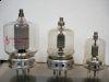
im thinking if i use a shunt bar (similar to the one attached), it'd be ok
Registered Member #1316
Joined: Thu Feb 14 2008, 03:35AM
Location: Cambridge, MA
Posts: 365
Current transformers can work reliably up to many MHz. They do use some patented distributed resistive termination scheme, but you can buy Pearson current transformers that provide accurate phase measurement to 100MHz+. Most of the DRSSTC controllers use a current transformer for phase accurate current sensing.
Unless you used a completely unsuitable core (something like powdered iron) the phase shift you are seeing is probably in the resistive shunt. Big shunt resistors like that typically have a very low resistance but a comparatively large inductance due to the large physical size, becoming predominately inductive around a few tens or hundreds of KHz.
Registered Member #2099
Joined: Wed Apr 29 2009, 12:22AM
Location: Los Altos, California
Posts: 1714
wrote ... here is a comparison of a non isolated resistive bridge (top waveform), vs a current transformer (bottom waveform) you can see the ~90 degree phase shift.
Are those nice pictures yours? What's the frequency, or the scope horizontal scale? An ideal current transformer with resistive load has no phase shift. What if some or all of the apparent phase shift is in the signal from resistive shunt, due to parasitic inductance, and/or from induced voltage in its scope-probe-and-ground loop? One way to check the latter is to connect probe signal and ground to the same end of current shunt.
wrote ... >>That Allegro series current sensor could probably have its range extended with appropriate external shunt resistor ... >>(mind the inductances) I'm thinking if i use a shunt bar (similar to the one attached), it'd be ok
To make a point about inductance in low-ohm circuits, here's a thought experiment using ACS732-ish values. Make a current divider by connecting two 1-milliohm resistors in parallel. Disturb the symmetry by adding, in just one branch, 1 nanohenry of equivalent series inductance. What is the current ratio between branches A and B, at 1 MHz? What is the phase difference between currents A and B at 100 kHz?
[edit] Written before but had to be re-typed. Nanohenries can be sneaky. Consider power supply bypass capacitors, on a multilayer circuit board with dedicated power and ground planes. Place leadless ceramic chip capacitors with vias right next to the pads. Each one comes with equivalent series inductance on the order of a nanohenry, when you include the connection loop.
Current transformer phase accuracy depends on the inductance reactance to shunt resistance ratio. Ideally it becomes a 100% accurate, if the shunt resistance is zero. In practice one has to add the copper resistance of the CT to the shunt resistance, so it never is really a 100% accurate. Usually the copper resistance can be neglected. Care hast to be taken, though, not to make the shunt resistance too large.
Registered Member #580
Joined: Mon Mar 12 2007, 03:17PM
Location: Melbourne, Australia
Posts: 410
wrote ... They do use some patented distributed resistive termination scheme, but you can buy Pearson current transformers that provide accurate phase measurement to 100MHz+.
ohhhhhhhhh! not that those prices :(
wrote ... Big shunt resistors like that typically have a very low resistance but a comparatively large inductance due to the large physical size, becoming predominately inductive around a few tens or hundreds of KHz.
given that everything is connected with clipleads, a shunt-bar is probably the least inductive part of the setup!
wrote ... Are those nice pictures yours?
"nice"? yes they are mine
wrote ... What's the frequency
probably about 320Khz, however it must work with different coils too without manually tuning some delay parameter
if i was to use a CT, seems i have to chose between a Flame Emitting Resistor
This site is powered by e107, which is released under the GNU GPL License. All work on this site, except where otherwise noted, is licensed under a Creative Commons Attribution-ShareAlike 2.5 License. By submitting any information to this site, you agree that anything submitted will be so licensed. Please read our Disclaimer and Policies page for information on your rights and responsibilities regarding this site.


 Phase accurate primary current sensing


 I bet it's based on Hall effect. What's the time delay corresponding to its 1 MHz bandwidth rating, and does the bandwidth vary widely with process and temperature?