If you need assistance, please send an email to forum at 4hv dot org. To ensure your email is not marked as spam, please include the phrase "4hv help" in the subject line. You can also find assistance via IRC, at irc.shadowworld.net, room #hvcomm.
Support 4hv.org!
Donate:
4hv.org is hosted on a dedicated server. Unfortunately, this server costs and we rely on the help of site members to keep 4hv.org running. Please consider donating. We will place your name on the thanks list and you'll be helping to keep 4hv.org alive and free for everyone. Members whose names appear in red bold have donated recently. Green bold denotes those who have recently donated to keep the server carbon neutral.
Special Thanks To:
Aaron Holmes
Aaron Wheeler
Adam Horden
Alan Scrimgeour
Andre
Andrew Haynes
Anonymous000
asabase
Austin Weil
barney
Barry
Bert Hickman
Bill Kukowski
Blitzorn
Brandon Paradelas
Bruce Bowling
BubeeMike
Byong Park
Cesiumsponge
Chris F.
Chris Hooper
Corey Worthington
Derek Woodroffe
Dalus
Dan Strother
Daniel Davis
Daniel Uhrenholt
datasheetarchive
Dave Billington
Dave Marshall
David F.
Dennis Rogers
drelectrix
Dr. John Gudenas
Dr. Spark
E.TexasTesla
eastvoltresearch
Eirik Taylor
Erik Dyakov
Erlend^SE
Finn Hammer
Firebug24k
GalliumMan
Gary Peterson
George Slade
GhostNull
Gordon Mcknight
Graham Armitage
Grant
GreySoul
Henry H
IamSmooth
In memory of Leo Powning
Jacob Cash
James Howells
James Pawson
Jeff Greenfield
Jeff Thomas
Jesse Frost
Jim Mitchell
jlr134
Joe Mastroianni
John Forcina
John Oberg
John Willcutt
Jon Newcomb
klugesmith
Leslie Wright
Lutz Hoffman
Mads Barnkob
Martin King
Mats Karlsson
Matt Gibson
Matthew Guidry
mbd
Michael D'Angelo
Mikkel
mileswaldron
mister_rf
Neil Foster
Nick de Smith
Nick Soroka
nicklenorp
Nik
Norman Stanley
Patrick Coleman
Paul Brodie
Paul Jordan
Paul Montgomery
Ped
Peter Krogen
Peter Terren
PhilGood
Richard Feldman
Robert Bush
Royce Bailey
Scott Fusare
Scott Newman
smiffy
Stella
Steven Busic
Steve Conner
Steve Jones
Steve Ward
Sulaiman
Thomas Coyle
Thomas A. Wallace
Thomas W
Timo
Torch
Ulf Jonsson
vasil
Vaxian
vladi mazzilli
wastehl
Weston
William Kim
William N.
William Stehl
Wesley Venis
The aforementioned have contributed financially to the continuing triumph of 4hv.org. They are deserving of my most heartfelt thanks.
Registered Member #3414
Joined: Sun Nov 14 2010, 05:05PM
Location: UK
Posts: 4245
Plasma wrote ...
You're still DC based About the first,one is a voltage source, ttop leg,the second is a current source. The one you posted for full isolation will need a cap from top left of the jfet to bottom right,adjust for series,but its still DC,try using 2 MOSFET with diode's at source to clip both ways
How is it still DC biased? There are two 10u caps blocking any DC?
If you mean there is still a voltage present, I did the maths..... there is 12.66V across the fet 'at rest'..... the load resistor is 246 Ohms.... the DC resistance of the tank is around 0.8Ohms..... the tank itself 'sees' 50mV..... I don't expect that to be an issue.....
Have I missed something?....
EDIT: I do now have all the components to build a long tailed pair, but I'd use these JFET's if I were to do so, I don't like the hard clipping of mosfet's..... That's one reason I'm only using jfet's for this, and my other audio projects.....
Registered Member #3414
Joined: Sun Nov 14 2010, 05:05PM
Location: UK
Posts: 4245
Plasma wrote ...
You're still DC based About the first,one is a voltage source, ttop leg,the second is a current source. The one you posted for full isolation will need a cap from top left of the jfet to bottom right,adjust for series,but its still DC,try using 2 MOSFET with diode's at source to clip both ways
What value should the diagonal capacitor be?
(Sorry mods for breaching the rules..... New question..... I don't do it often..... )
Registered Member #61406
Joined: Thu Jan 05 2017, 11:31PM
Location:
Posts: 268
The diagonal caps should be greater than 10uF ,but that covers a driving ac source,if you want to drive a amplifier just match the series capatance It DC bais because the voltage drops to from peak, but doesn't go negative
Registered Member #3414
Joined: Sun Nov 14 2010, 05:05PM
Location: UK
Posts: 4245
Plasma wrote ...
The diagonal caps should be greater than 10uF ,but that covers a driving ac source,if you want to drive a amplifier just match the series capatance It DC bais because the voltage drops to from peak, but doesn't go negative
The load is three tiny coils with a total inductance of just over 1mH. It can be treated like any other coil, say a small speaker..... It also has a series resistance, currently of around 235 Ohms.
There is no DC current, due to the blocking caps.....
It's basically a single ended class A amp driving into a coil with a series resistor....
While the impedence of the coil increases to around 80 Ohms at 10kHz, at 0Hz the coil 'sees' 50mV.
If a single ended Class A amp works fine with a DC voltage bias, surely this should as well?....
Am I missing something?..... I could implement a long tailed pair, or even an H bridge, but if single ended class A is good enough to drive a speaker, why is this circuit not suitable to drive a siminar inductive load?
EDIT: When I say single ended class A, I mean a parafeed type circuit with a parafeed capacitor that blocks the DC component, so a gapped O/T is not required, as there is no DC component.
Registered Member #3414
Joined: Sun Nov 14 2010, 05:05PM
Location: UK
Posts: 4245
So, New information....
I've been doing a bit of online research, apparently, this topology, with the cap referenced to the source is generally called 'ultrafeed topology'. It has pro's and con's, the cons being about isolation..... in the case of failure of an O/T, the plate voltage is not isolated. That's not really an issue with a drain potential of 19V. It appeals to me because it defies the rules of the usual descriptors regarding voltage and current, it's effectively both. It doesn't really matter in which leg you place the cap, it's in series between them.
It also excels as an ungrounded low impedence source.
Anyway, back to the current question, regarding how 'isolated' this circuit needs to be. I've come to the conclusion after extensive googling that the issues regarding inadequate isolation all seem to relate to ground loop problems. That was my understanding when I designed it and that is why I chose the ultrafeed topology. I'm also aware that these were traditionally driven from O/T's running from tube stages. As the load is just an inductive load, like a transformer primary, I can't see that any more isolation would be required, although I do understand the meaning of 'total isolation', especially when related to safety and higher voltages. I propose to order a couple of small audio transformers for delivery on Tuesday, and then try my original circuit both with and without 'total isolation'. That would appear to be the most pragmatic approach, before I start building a long tailed pair, or H bridge, or something.
There is another isolation issue relating to power supply ripple rejection, but my power supply is completely ripple free.
In the meantime, I'll get on and build the recovery stage.....
I do plan to use the transformers for other purposes, one is ideal for driving a long tailed pair, the other for driving an H bridge. (It's likely that the power stage of an amp I'm building is likely to consist of a class A power JFET H bridge, with choke regulation. Something I've never seen attempted before )
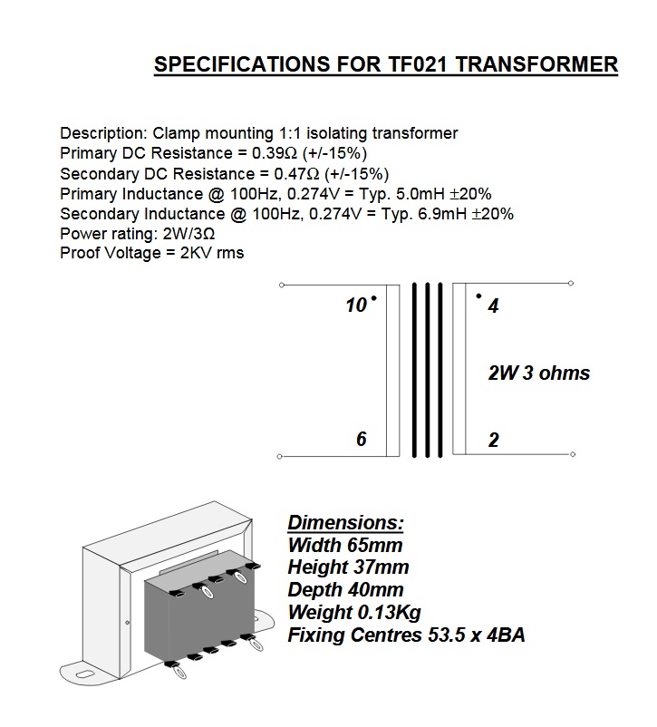
Transformer is 2W, 1:1, nominally 3 Ohm, but is good for 15 Ohm, 20Hz, which is well below what I'll be putting through it here.
EDIT: There appears to be an issue with some of the links to images below..... I'll try and sort it.
Registered Member #3414
Joined: Sun Nov 14 2010, 05:05PM
Location: UK
Posts: 4245
Here's the 'recovery' circuit.... the circuit that amplifies the output from the spring reverb tank back up to line level.....
I could leave out the input gate resistor and up to four capacitors, but as I'm testing it at the transistor voltage limits, they do add some protection in the case of transistor failure.
This circuit has yet to be tested, but is basically two of the boost stages that drives the output stage for the tank input.
More to come in due course.....
EDIT: The input cap and resistor form a high pass filter, although it currently passes pretty much everything, but could be 'tweaked' if required, also there's room on the left hand side of the board to add a low pass filter if this turns out to be required.....
Registered Member #3215
Joined: Sun Sept 19 2010, 08:42PM
Location:
Posts: 780
would I have known about the load, I wouldn't have told you about isolation :) the transformer is giving you that already so no real need of long tailed pair or anything, just DC blocking will be sufficient
I personally tried hooking up a PAM8403 module to a small toroïdal transformer to match a tube phase splitter, or even a PP stage directly, to avoid half the iron with replacing power supply by a PLC stage with a current limit... would have made nice, easy instrument amplifiers (please give me shares if you start a business on this idea ;) )
Registered Member #3414
Joined: Sun Nov 14 2010, 05:05PM
Location: UK
Posts: 4245
Shrad wrote ...
would I have known about the load, I wouldn't have told you about isolation :) the transformer is giving you that already so no real need of long tailed pair or anything, just DC blocking will be sufficient
I personally tried hooking up a PAM8403 module to a small toroïdal transformer to match a tube phase splitter, or even a PP stage directly, to avoid half the iron with replacing power supply by a PLC stage with a current limit... would have made nice, easy instrument amplifiers (please give me shares if you start a business on this idea ;) )
It works fine without the transformer. Once I got thinking I realised there was no good reason not to use one, although the only good reasons I could think of for using one is that the famous Fender units from the Sixties all had transformers, so maybe it was a part of the sound. Also, it was simpler to reverse the phase, which I did do. Phase shouldn't in theory be important in this application (reverb driver), but the waveforms seem to match better one way round. I'm still playing with it all, added active splitter and combiner, it's pumping 50mA or more, still playing with trimpots and cap values, and I need to add attenuation to the output.....
This site is powered by e107, which is released under the GNU GPL License. All work on this site, except where otherwise noted, is licensed under a Creative Commons Attribution-ShareAlike 2.5 License. By submitting any information to this site, you agree that anything submitted will be so licensed. Please read our Disclaimer and Policies page for information on your rights and responsibilities regarding this site.


 Function and form....

 )
)


