If you need assistance, please send an email to forum at 4hv dot org. To ensure your email is not marked as spam, please include the phrase "4hv help" in the subject line. You can also find assistance via IRC, at irc.shadowworld.net, room #hvcomm.
Support 4hv.org!
Donate:
4hv.org is hosted on a dedicated server. Unfortunately, this server costs and we rely on the help of site members to keep 4hv.org running. Please consider donating. We will place your name on the thanks list and you'll be helping to keep 4hv.org alive and free for everyone. Members whose names appear in red bold have donated recently. Green bold denotes those who have recently donated to keep the server carbon neutral.
Special Thanks To:
Aaron Holmes
Aaron Wheeler
Adam Horden
Alan Scrimgeour
Andre
Andrew Haynes
Anonymous000
asabase
Austin Weil
barney
Barry
Bert Hickman
Bill Kukowski
Blitzorn
Brandon Paradelas
Bruce Bowling
BubeeMike
Byong Park
Cesiumsponge
Chris F.
Chris Hooper
Corey Worthington
Derek Woodroffe
Dalus
Dan Strother
Daniel Davis
Daniel Uhrenholt
datasheetarchive
Dave Billington
Dave Marshall
David F.
Dennis Rogers
drelectrix
Dr. John Gudenas
Dr. Spark
E.TexasTesla
eastvoltresearch
Eirik Taylor
Erik Dyakov
Erlend^SE
Finn Hammer
Firebug24k
GalliumMan
Gary Peterson
George Slade
GhostNull
Gordon Mcknight
Graham Armitage
Grant
GreySoul
Henry H
IamSmooth
In memory of Leo Powning
Jacob Cash
James Howells
James Pawson
Jeff Greenfield
Jeff Thomas
Jesse Frost
Jim Mitchell
jlr134
Joe Mastroianni
John Forcina
John Oberg
John Willcutt
Jon Newcomb
klugesmith
Leslie Wright
Lutz Hoffman
Mads Barnkob
Martin King
Mats Karlsson
Matt Gibson
Matthew Guidry
mbd
Michael D'Angelo
Mikkel
mileswaldron
mister_rf
Neil Foster
Nick de Smith
Nick Soroka
nicklenorp
Nik
Norman Stanley
Patrick Coleman
Paul Brodie
Paul Jordan
Paul Montgomery
Ped
Peter Krogen
Peter Terren
PhilGood
Richard Feldman
Robert Bush
Royce Bailey
Scott Fusare
Scott Newman
smiffy
Stella
Steven Busic
Steve Conner
Steve Jones
Steve Ward
Sulaiman
Thomas Coyle
Thomas A. Wallace
Thomas W
Timo
Torch
Ulf Jonsson
vasil
Vaxian
vladi mazzilli
wastehl
Weston
William Kim
William N.
William Stehl
Wesley Venis
The aforementioned have contributed financially to the continuing triumph of 4hv.org. They are deserving of my most heartfelt thanks.
Registered Member #3395
Joined: Thu Nov 04 2010, 08:42AM
Location: Christchurch, New Zealand
Posts: 193
Good troubleshooting so far. Your observation that the power supply's fan (I'm assuming it's of a similar nature to a SMPS with overload sense and protection, like a computer ATX PSU) shuts down could suggest there is an effective short circuit in the circuit somewhere.
I notice from the recent picture that the sources of the FETs don't appear to be connected to each other - they should both be connected together and to the negative rail.
It is also likely that during the few times you have tried operating this ZVS, and because it's not functioning properly, some solid state parts such as the diodes or FETs may have been damaged as they are sensitive. Once you have connected the FETs' sources together and to the negative rail (if they aren't already) - try replacing the zener diodes first. Usually a failed diode means it won't clamp and the PSU current will flow through to ground via the 470 ohm resistor. If it doesn't work after replacing the diodes, remove the FETs and test them using a video on Youtube to help.
Let us know how it goes after the above suggestions :)
Registered Member #58279
Joined: Sat Jan 09 2016, 05:39AM
Location: Houston, TX
Posts: 13
Thanks again kiwihvguy, you don't know how many times I poured over this circuit and never noticed the two mistakes you found. I had already desoldered all the components before you sent your message because I wasn't happy with how sloppy the whole thing looked. I'm waiting for a new protoboard to arrive tomorrow and I will rebuild it from scratch while remembering the previous errors I made. I tested all the components...both zeners, the FETs, resistors, and the UF4007s, all are in good working order so thankfully nothing got damaged. I'll report back tomorrow. Thanks again for your help, it is very much appreciated.
Registered Member #58279
Joined: Sat Jan 09 2016, 05:39AM
Location: Houston, TX
Posts: 13
I hadn't posted an update for a couple of days because I've been busy, but I did receive the new protoboard but before wasting it, I decided to solder together an extra set of components for a ZVS driver just to make sure it worked before putting it together on a board.
It still doesn't work...and I have no idea why. All the components are the same except for the fets which are IRFP250s instead of 260s. The zeners are 12v. I took a few pics of the setup and put them in an album, its much easier to see what is connected where as there is no board so perhaps the added transparency can reveal any mistake I may be making.
Registered Member #3395
Joined: Thu Nov 04 2010, 08:42AM
Location: Christchurch, New Zealand
Posts: 193
From your quick lash-up, which I also did for my first ZVS too, both the UF and zener diodes appear to be in the correct place and going to and from the correct terminals in the circuit.
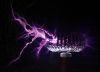
One potential issue I noticed: are you sure both halves of the primary winding on the flyback are both going in the same direction? It appears that the connections to the outermost part of the coils come out of the bottom, where in fact for both windings to be in the same direction, one of the outermost connections should come out the top. In other words, reverse the direction of one half of the primary winding.
If that doesn't sort it, then I will need to check in with how you actually tested the diodes and mosfets to confirm they were functional.
The fact that changing the capacitance values for the tank capacitor indicates that it's not actually the problem, as in something other than the capacitors was causing the issue.
I would try using a 12V SLA as the PSU for a change to see if it works or not, computer PSUs are a bit finicky in trying to make them reliably operate.
I'm very happy to help on here, I once was helped out on here so I like the opportunity to give back to the community :)
Registered Member #4074
Joined: Mon Aug 29 2011, 06:58AM
Location: Australia
Posts: 335
Kiwihvguy wrote ...
One potential issue I noticed: are you sure both halves of the primary winding on the flyback are both going in the same direction? It appears that the connections to the outermost part of the coils come out of the bottom, where in fact for both windings to be in the same direction, one of the outermost connections should come out the top. In other words, reverse the direction of one half of the primary winding.
I think Kiwihvguy has spotted the issue. It does look like the two halves of the primary coil are wound in opposite directions (opposite phasing). A simple way to visualize this: Imagine winding a single continuous coil without stopping, then soldering a tap onto the center turn. As Kiwihvguy said, you will notice that the direction of the coil never changes, so one end of the wire should exit "above" the ferrite core, and the other "below" (if the flyback is laying on it's side like in the last batch of photos).
Using two separate pieces of wire and winding the coils in the same direction is usually the most convenient option, as winding a coil of enameled wire, stripping the middle turn and isolating it from the core, then soldering the tap is fiddly.
Registered Member #58279
Joined: Sat Jan 09 2016, 05:39AM
Location: Houston, TX
Posts: 13
Kiwihvguy wrote ...
From your quick lash-up, which I also did for my first ZVS too, both the UF and zener diodes appear to be in the correct place and going to and from the correct terminals in the circuit.
One potential issue I noticed: are you sure both halves of the primary winding on the flyback are both going in the same direction? It appears that the connections to the outermost part of the coils come out of the bottom, where in fact for both windings to be in the same direction, one of the outermost connections should come out the top. In other words, reverse the direction of one half of the primary winding.
If that doesn't sort it, then I will need to check in with how you actually tested the diodes and mosfets to confirm they were functional.
The fact that changing the capacitance values for the tank capacitor indicates that it's not actually the problem, as in something other than the capacitors was causing the issue.
I would try using a 12V SLA as the PSU for a change to see if it works or not, computer PSUs are a bit finicky in trying to make them reliably operate.
I'm very happy to help on here, I once was helped out on here so I like the opportunity to give back to the community :)
The way I tested the mosfets was by using the diode test function on the multimeter, connecting the negative lead to the source and the positive lead to the drain, it showed 0 volts. When I touched the positive lead to the gate and then back to the drain, it showed a voltage. When I shorted the gate and drain pins with my finger, the voltage dropped back down to 0 and stayed there. Also, the mosfets are new, I never used them before, they were extras from another project. The way I tested the diodes was also by using the diode test function on the multimeter and comparing the result to the same test run on the same diode that was new and never used, the values were identical.
I tried a 12v and 24v psu, neither of them worked. I know the flyback is good because I have another ZVS driver that I purchased premade and when I connect it to that flyback, everything works great, the arcs travel up the jacob's ladder as its supposed to do. This is the ZVS driver I purchased, the flyback that came with it is the one you see in the picture.
Registered Member #58279
Joined: Sat Jan 09 2016, 05:39AM
Location: Houston, TX
Posts: 13
So I made an observation that I can't explain. I connected a 12v power supply to the ZVS and measured a few points throughout the circuit. First, I measured the gate of the left mosfet and it was showing 12v, the gate of the second mosfet read .600v, not sure why that is. I checked the resistors prior to starting and they both measured correctly, 470 ohm 2 w resistors.
Unless you're using a scope you're not going to get any meaningful measurements from a DMM, save perhaps an AC measurement across the tank capacitor. If there's continuous DC present at any gate (the kind of signal a DMM could actually measure), the driver has latched up and entered a failure state.
This site is powered by e107, which is released under the GNU GPL License. All work on this site, except where otherwise noted, is licensed under a Creative Commons Attribution-ShareAlike 2.5 License. By submitting any information to this site, you agree that anything submitted will be so licensed. Please read our Disclaimer and Policies page for information on your rights and responsibilities regarding this site.


 Problems getting ZVS driver to work