If you need assistance, please send an email to forum at 4hv dot org. To ensure your email is not marked as spam, please include the phrase "4hv help" in the subject line. You can also find assistance via IRC, at irc.shadowworld.net, room #hvcomm.
Support 4hv.org!
Donate:
4hv.org is hosted on a dedicated server. Unfortunately, this server costs and we rely on the help of site members to keep 4hv.org running. Please consider donating. We will place your name on the thanks list and you'll be helping to keep 4hv.org alive and free for everyone. Members whose names appear in red bold have donated recently. Green bold denotes those who have recently donated to keep the server carbon neutral.
Special Thanks To:
Aaron Holmes
Aaron Wheeler
Adam Horden
Alan Scrimgeour
Andre
Andrew Haynes
Anonymous000
asabase
Austin Weil
barney
Barry
Bert Hickman
Bill Kukowski
Blitzorn
Brandon Paradelas
Bruce Bowling
BubeeMike
Byong Park
Cesiumsponge
Chris F.
Chris Hooper
Corey Worthington
Derek Woodroffe
Dalus
Dan Strother
Daniel Davis
Daniel Uhrenholt
datasheetarchive
Dave Billington
Dave Marshall
David F.
Dennis Rogers
drelectrix
Dr. John Gudenas
Dr. Spark
E.TexasTesla
eastvoltresearch
Eirik Taylor
Erik Dyakov
Erlend^SE
Finn Hammer
Firebug24k
GalliumMan
Gary Peterson
George Slade
GhostNull
Gordon Mcknight
Graham Armitage
Grant
GreySoul
Henry H
IamSmooth
In memory of Leo Powning
Jacob Cash
James Howells
James Pawson
Jeff Greenfield
Jeff Thomas
Jesse Frost
Jim Mitchell
jlr134
Joe Mastroianni
John Forcina
John Oberg
John Willcutt
Jon Newcomb
klugesmith
Leslie Wright
Lutz Hoffman
Mads Barnkob
Martin King
Mats Karlsson
Matt Gibson
Matthew Guidry
mbd
Michael D'Angelo
Mikkel
mileswaldron
mister_rf
Neil Foster
Nick de Smith
Nick Soroka
nicklenorp
Nik
Norman Stanley
Patrick Coleman
Paul Brodie
Paul Jordan
Paul Montgomery
Ped
Peter Krogen
Peter Terren
PhilGood
Richard Feldman
Robert Bush
Royce Bailey
Scott Fusare
Scott Newman
smiffy
Stella
Steven Busic
Steve Conner
Steve Jones
Steve Ward
Sulaiman
Thomas Coyle
Thomas A. Wallace
Thomas W
Timo
Torch
Ulf Jonsson
vasil
Vaxian
vladi mazzilli
wastehl
Weston
William Kim
William N.
William Stehl
Wesley Venis
The aforementioned have contributed financially to the continuing triumph of 4hv.org. They are deserving of my most heartfelt thanks.
Registered Member #477
Joined: Tue Jun 20 2006, 11:51PM
Location: Seattle, WA
Posts: 546
It was an impulse purchase. I saw some Powerex CM1000HA-28H’s on a shelf at my favorite local surplus shop. I knew they were IGBT bricks, but nothing immediately told me what they were good for. I bought one anyway. $50 + tax. I don’t even know if it works. Briefly, the ratings are: Vce=1400V, Ic=1000A, pulse current = 2000A. If it *does* work, seems like it was probably a really good buy!
Here’s the datasheet:
Initially, I thought it would just be a fun thing to tinker with, but seeing the 2000A rating, I’m left wondering if this would be a good choice for a single-element SISG, e.g. for an "off-line" coil. Certainly the Vce is more than enough! What do those of you more familiar with these bricks think? Did I waste my money? If it’s broken, I’m sure the answer is YES! I suppose I need to wire up some kind of test rig now.
In the OL-SISG scenario, I suppose I’d use voltage-doubled 240V to charge up a few dozen uF’s and mate this with a single SISG element using this brick and two 300V SIDACs. Doubtless some of the other component values (resistors, cap) need tweaking to accommodate the brick. I haven’t thought too much about that. Will it be able to drive this brick? If not, perhaps a more “classical†OLTC design is in order, but I’m not sure I’m geeky enough to pull one of those out of my hat
Lastly: Can anybody suggest a relatively safe-n-sane method of putting this thing through its paces that'll give me fair confidence that it's in good shape? I'd hate to burn a lot of energy planning a coil around it and then find out it's a goner and that a working one will be $100's. That's a trap I'd prefer not to fall into!! )
Registered Member #30
Joined: Fri Feb 03 2006, 10:52AM
Location: Glasgow, Scotland
Posts: 6706
Hi Aaron
I used two of the slightly smaller CM600HA-24H in parallel in my OLTC2. After a lot of tinkering I got it to run at over 4kW of power and produce 80" sparks. Your brick is probably good for somewhat more. The peak current rating seems to be just a guideline, since the peaks in a Tesla coil circuit are much shorter than the 1ms pulses that Powerex specify them for. Mine were rated at 1200A peak, but I think I ended up running them at something like 4500A peak
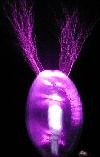
When I got my CM600HA-24Hs, I built a test fixture with some MO caps and a single turn loop inductor to pulse current through them:
The OLTC is really not too different to the SISG. As far as I'm concerned, the main difference is that I developed the OLTC to use DC resonant charging. This makes the most efficient use of the components, but Terry's SISG trigger circuit can't cope with that (it would fire just once and then stick on forever) I'm working on that, but I am stuck for a way to do it without ruining the simplicity of Terry's circuit :(
Registered Member #477
Joined: Tue Jun 20 2006, 11:51PM
Location: Seattle, WA
Posts: 546
Thanks, Steve!
4500A is a lot of amps! How do those Geek caps fare at those hideous currents?
A simple ~100W design might be: - Voltage double my 240V, 60Hz mains - 600V firing voltage - Terry's "Piranha" charging topology (second edition) - This all suggests a 60bps firing rate, yes? - 10uF + 600Vpk + 60bps => 108W coil power - ~1uH single-loop primary => ~1900A peak primary current!!! - ~50kHz resonant frequency (seems "ok")
All this for what will surely be some pretty wimpy sparks!! But hey, if it works at all, it'd certainly be one of the simpler OLTC-ish..."things"...out there The primary peak current makes me worried for the tank cap, though. Even the 600VDC-rated CDE942C's top out at around 1500A. I'd prefer not to have them going off like firecrackers! Would the 600VDC ones survive? They come in 2.5uF, so I'd only need four of them! That would sure be convenient.
EDIT: Actually, I'm thinking about the cap current all wrong, aren't I? Haven't done much MMC'ing. The per-string current is the peak current divided by the number of strings, yes? So with four "strings" (of one cap each ), I only see ~500A per cap. Ok, maybe that's not so scary after all.
Measure the resistance from the gate to the emitter and collector in both directions (positive to negative and negative to postive). In all cases, the gate resistance to the other terminals should be "infinite" or look like a say 200nF capacitance (!!!). If there is resistance, it has been damaged but "might" still work.
Take a 9V battery and charge the emitter to gate to -9v. The collector to emitter should look open. Then charge the gate to +9v and the collector to emitter should look shorted. If it does that without any trouble, it is good Typicaly if these bricks fail, there is case damage as in cracking. But the electrical test is really good for detecting damage. Surplus parts like these are typically removed when another brick blows and they replace all of them. In many cases the other bricks are fine.
It could be used as an SISG easily and you can probably just add another SIDAC to make it fire at 1200V. Then just use it as a OLTC type thing. The 200nF needs some thought though since that is 40X normal for an SISG IGBT. I will have to think on that You probably can just eliminate the 100nF cap and hope the turn-on is "slow" enough to allow it to reach say 24V on the gate before the IGBT takes over. Or, go to a 1uF cap...
Registered Member #205
Joined: Sat Feb 18 2006, 11:59AM
Location: Skørping, Denmark
Posts: 741
Neve C. Stoner wrote ...
I developed the OLTC to use DC resonant charging. This makes the most efficient use of the components, but Terry's SISG trigger circuit can't cope with that (it would fire just once and then stick on forever)
Could you explain why it will stay on forever?
I thought the SISG circuit could work this way, if it was fed trough a charging choke with a voltage lower than half of the Sidac`s breakdown voltage: A Thyristor, or an IGBT, is connected to short out 3/4 of the Sidacs. The first ringdown is initiated when this SCR or IGBT is triggered. When the double voltage, due to the charging choke arrives at the primary cap, it is stil not enough to force breakdown of the Siac`s, so the trigger elements still have to be operated for another ringdown. This would enable full remote triggering of the coil. I have an idea for a trigger circuit.
But of course, if it doesn`t quench after the first ringdown, this won`t work.
Registered Member #477
Joined: Tue Jun 20 2006, 11:51PM
Location: Seattle, WA
Posts: 546
Terry Fritz wrote ...
Hi, First to test it. (verbose testing instructions snipped)
Thanks Terry, Steve. Wish I'd read this last night! Now I'm at work and itching to get home and try it out!!
Terry, one SISG question: Where does the 785A/us figure in the SISG PDF come from? (this in your 250kHz 500A Ipk example). I'm trying to understand this section of the doc a bit better now so that I can work out the implications of the capacitor (e.g., if 1uF were used).
Registered Member #30
Joined: Fri Feb 03 2006, 10:52AM
Location: Glasgow, Scotland
Posts: 6706
Hi Finn, all,
These are the problems I expected to happen with DC resonant charging:
1: Terry's SISG won't be able to run with discontinuous current unless it's modified to trigger on command. This is because it's triggered by voltage, and once the inductor current falls to zero, the voltage will quit increasing. Therefore, the closest you can get is to tune the voltage such that it fires exactly as the charge current stops. This won't be possible to do exactly due to circuit tolerances, therefore in practice the SISG would always end up firing before the charging current stopped, and hence the charging current would never stop.
2: The average voltage across an inductor is always zero. (not counting IR drop, but at the high voltages and low currents in Tesla coil circuits, it may be possible to neglect this.) Put another way: Inductors don't ballast DC!
3: Terry's circuit stays on for rather a long time, during which time the inductor is shorted across the power supply and the current will ramp up quickly. This could cause boost converter action which would be self-reinforcing.
Due to the interaction of these three factors, I'd expect a SISG running off DC to run away, with the breakrate increasing and inductor current ramping up until the SISG stuck on permanently and blew the power supply out. It might be possible to find a power supply voltage setting that gave stable running, but I'd expect it to be very touchy. I thought of some ways to tame it:
1: Use command resonant charging to force discontinuous current. Unfortunately this needs a high voltage switch that can be triggered, and if we had a reliable triggerable HV switch, we could just have...
2: Achieved discontinuous current operation by making the SISG itself triggerable. This would make it more complicated.
3: Add resistive ballast in series with the charging choke. This wastes power, though, and would probably just tame the instability a little rather than getting rid of it altogether.
4: Use hybrid DC/AC resonant charging with a full-wave rectified unfiltered HV transformer. Run this off a lamp dimmer type of circuit to cause zero periods in every half cycle where the SISG can have a chance to recover. This is really just command resonant charging with the HV switch moved to the primary side of the power transformer and the breakrate fixed to 100/120Hz as a consequence. (You should find a dimmer setting where the breakrate is exactly 100/120.) The charging choke could be replaced with an ordinary ballast on the primary too.
I got a couple of SISG modules from Terry, and I hoped to try this stuff out, but the more I look at his original design, the more it seems to "just work fine" as it is.
Terry, one SISG question: Where does the 785A/us figure in the SISG PDF come from? (this in your 250kHz 500A Ipk example). I'm trying to understand this section of the doc a bit better now so that I can work out the implications of the capacitor (e.g., if 1uF were used).
See this:
It is the change of current vs. time equation. A calculus derivative.
Stever McStoner Mc Connerr... said :o))
Something like the SISG might not run well off a pure DC source. But a little resistance will probebaly drop the source "enough"... Think a simple RC filter there for isolation. In the PIRANHA, the MOT's inductance really is the only isolation along with minimal curent limiting from the MOT.
It woorks good!! That giant 165nF primary cap is not "trivial" to charge!!! The "DC" supply would have to charge it back to say 6800V in 500us for it to "hang on".
Registered Member #30
Joined: Fri Feb 03 2006, 10:52AM
Location: Glasgow, Scotland
Posts: 6706
Terry, I never quite understood your voltage doubler charging arrangement. As far as I can tell, it has to either fire at 60bps, or else only charge half of the tank cap for each bang. In the latter case it would waste 3/4 of the energy capability of the cap?
This site is powered by e107, which is released under the GNU GPL License. All work on this site, except where otherwise noted, is licensed under a Creative Commons Attribution-ShareAlike 2.5 License. By submitting any information to this site, you agree that anything submitted will be so licensed. Please read our Disclaimer and Policies page for information on your rights and responsibilities regarding this site.


 Really big brick - Off-line SISG coil?


 I suppose I need to wire up some kind of test rig now.

 But hey, if it works at all, it'd certainly be one of the simpler OLTC-ish..."things"...out there
 Or, go to a 1uF cap...