If you need assistance, please send an email to forum at 4hv dot org. To ensure your email is not marked as spam, please include the phrase "4hv help" in the subject line. You can also find assistance via IRC, at irc.shadowworld.net, room #hvcomm.
Support 4hv.org!
Donate:
4hv.org is hosted on a dedicated server. Unfortunately, this server costs and we rely on the help of site members to keep 4hv.org running. Please consider donating. We will place your name on the thanks list and you'll be helping to keep 4hv.org alive and free for everyone. Members whose names appear in red bold have donated recently. Green bold denotes those who have recently donated to keep the server carbon neutral.
Special Thanks To:
Aaron Holmes
Aaron Wheeler
Adam Horden
Alan Scrimgeour
Andre
Andrew Haynes
Anonymous000
asabase
Austin Weil
barney
Barry
Bert Hickman
Bill Kukowski
Blitzorn
Brandon Paradelas
Bruce Bowling
BubeeMike
Byong Park
Cesiumsponge
Chris F.
Chris Hooper
Corey Worthington
Derek Woodroffe
Dalus
Dan Strother
Daniel Davis
Daniel Uhrenholt
datasheetarchive
Dave Billington
Dave Marshall
David F.
Dennis Rogers
drelectrix
Dr. John Gudenas
Dr. Spark
E.TexasTesla
eastvoltresearch
Eirik Taylor
Erik Dyakov
Erlend^SE
Finn Hammer
Firebug24k
GalliumMan
Gary Peterson
George Slade
GhostNull
Gordon Mcknight
Graham Armitage
Grant
GreySoul
Henry H
IamSmooth
In memory of Leo Powning
Jacob Cash
James Howells
James Pawson
Jeff Greenfield
Jeff Thomas
Jesse Frost
Jim Mitchell
jlr134
Joe Mastroianni
John Forcina
John Oberg
John Willcutt
Jon Newcomb
klugesmith
Leslie Wright
Lutz Hoffman
Mads Barnkob
Martin King
Mats Karlsson
Matt Gibson
Matthew Guidry
mbd
Michael D'Angelo
Mikkel
mileswaldron
mister_rf
Neil Foster
Nick de Smith
Nick Soroka
nicklenorp
Nik
Norman Stanley
Patrick Coleman
Paul Brodie
Paul Jordan
Paul Montgomery
Ped
Peter Krogen
Peter Terren
PhilGood
Richard Feldman
Robert Bush
Royce Bailey
Scott Fusare
Scott Newman
smiffy
Stella
Steven Busic
Steve Conner
Steve Jones
Steve Ward
Sulaiman
Thomas Coyle
Thomas A. Wallace
Thomas W
Timo
Torch
Ulf Jonsson
vasil
Vaxian
vladi mazzilli
wastehl
Weston
William Kim
William N.
William Stehl
Wesley Venis
The aforementioned have contributed financially to the continuing triumph of 4hv.org. They are deserving of my most heartfelt thanks.
Registered Member #140
Joined: Sat Feb 11 2006, 11:43AM
Location: The Netherlands
Posts: 14
Hello,
I'm building my third drsstc. I will be running with a Fres of 40 Khz. The coil is finished already. The MMC is also almost ready. But i'm still working on the electronics. The driver will be Steve Connor's pll driver, so that shouldn't be a problem hopefully.
But I still have some questions about the full bridge. I got a 1200 Volt 3000 A 3phase igbt module which I want to use for the coil. I haven't found a datasheet yet so I don't know the switching times but I will give it a try. If it doesn't work I will switch to a fullbridge with 300 A 1200 V igbts.
The igbt I want to use is a pp30012hs. And contains 3 half bridges in one module. The layout of the full bridge should have very low inductance because I don't think it's a very fast igbt So does anybody have some suggestions for a very low inductance layout ? I have some ideas but I need to draw it before I can explain it. My english ain't that good so.
I have attached a picture of the igbt module on the heatsink.
Registered Member #162
Joined: Mon Feb 13 2006, 10:25AM
Location: United Kingdom
Posts: 3140
Operating at 40 kHz means (usually) moderate dI/dT so unwanted voltages across stray inductances (E=L.dI/dT) are moderate also hence you need not go to extremes to achieve low stray inductance though you should still keep it low. A good quality invertor-grade capacitor with short thick wires to the bridge should be ok anything better would be excellent!
In your mind, draw out the path that the main current takes then minimise the area enclosed by the current path.
Registered Member #146
Joined: Sun Feb 12 2006, 04:21AM
Location: Austin Tx
Posts: 1055
What would be ideal is a laminate bus assembly. What i like to use is 2 sided copper clad board as the base, then solder thick copper sheeting onto it to give it the conductor size required. Anyway, you devote one side of the board to be the + and the other the -. Drill holes and remove copper where connections are needed. Connect your large electrolytic capacitors to this same double sided copper sheet. When using large sheets as conductors, you get far less inductance than if you used wires. Making the sheets wider lowers the inductance (as its similar to paralleling many small inductors). Here are some large H-bridges i have designed:
Check out the pictures in each of those links. Your job is a little easier since they put the +/- terminals for each bridge in a convenient place.
Also, these big IGBTs can be switched a bit faster than spec sheets may suggest because we arent hard switching quite so much current.
Do you have any pictures of your previous 2 DRSSTCs?
Registered Member #140
Joined: Sat Feb 11 2006, 11:43AM
Location: The Netherlands
Posts: 14
Thanks for the ideas
I was also thinking about a laminate bus assembly like you mentoined Steve. And got some good ideas from your pictures.
The only problem is I got to put 2 caps in serie (sorry don't know the english word for it but it's the opposite from putting the caps parralel) I want to power the coil with 230 vac rectiefied and doubled. I got 4 12000 uF 200 vdc caps who I want to put in serie so I get 3000 uF at 800 vdc. And connect these caps to the bridge with short and thick wires (25mm²). And on the copper plate I want to put 2 1900 uF 400 vdc caps in serie. I don't have any snubber caps so I want to keep the inductance as low as possible.
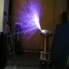
Attached is a picture of the coil. I don't have any pictures of my old drsstc's on this computer but wil post them when I find them
Registered Member #76
Joined: Thu Feb 09 2006, 10:04AM
Location: Hemer, Germany
Posts: 458
you really need those snubber capacitors in your bridge design to prevent the whole thing from ringing up. when this ringing occurs the voltage increases to maybe twice the voltage rating of your igbt module, its very dangerous. you dont need so many yF like steve uses only 1yF decoupling can help you a lot if you use good caps. for a bridge this size is suggest using 10yf or more very close to your igbt brick.
Registered Member #140
Joined: Sat Feb 11 2006, 11:43AM
Location: The Netherlands
Posts: 14
Well I don't have any snubber caps. And I don't have a source to buy them cheap And I believe Steve Connor also doesn't use snubber caps on the full bridge of his new drsstc (odin the all fragger) I'm trying to keep the layout as low inductance as possible with the caps very close to the igbt. So I hope it will survive without snubber caps. I`m aware of the potentional problem but I will scope the whole thing beforce turning it to 11.
Registered Member #30
Joined: Fri Feb 03 2006, 10:52AM
Location: Glasgow, Scotland
Posts: 6706
Odin hasn't been tested yet (and probably won't be tested for a while due to me being real busy with work) so YMMV.
I did find on my 220kHz DRSSTC, that certain values of snubber caps could make the ringing worse than it was with the electrolytic alone. But I also found other values that made it a good deal better. I never tried running it at full power with no snubber caps.
Registered Member #140
Joined: Sat Feb 11 2006, 11:43AM
Location: The Netherlands
Posts: 14
Well I could try to find some snubber on ebay or something. Just to be shure. Any ideas on what amount of snubbber caps would be good ? Or should I try different values and measure which gives the best performance ?
I'm probally going to buy the copper clad tommorow and finish the full bridge.
Registered Member #146
Joined: Sun Feb 12 2006, 04:21AM
Location: Austin Tx
Posts: 1055
For the record, my DRSSTC-2 system has had its highest power , and longest runs with no snubber capacitors installed, only the main electrolytics. Unless i find some reason to change it, this is how it will remain. I found that even adding little 2uF low inductance caps on the buss increased the ringing of the buss voltage, probably because it increased the Q of the buss. I use large inverter grade capacitors on that coil, so they have lower ESR than computer grade caps, so as Conner says, "your mileage may vary".
Jorrit, I also have to series lytics on my coil. Make a third layer to your laminate, use thick wide sheets to make the series connection. This will keep the inductance down. Hope this idea is clear enough. Keep in mind that all of the capacitors in series form a "loop" that is in series with the IGBTs, so you must keep *all* of these inductances low.
Thats a serious looking coil setup, what are the dimensions of the secondary?
Registered Member #15
Joined: Thu Feb 02 2006, 01:11PM
Location:
Posts: 3068
wrote ...
I found that even adding little 2uF low inductance caps on the buss increased the ringing of the buss voltage, probably because it increased the Q of the buss.
With a snubber you need a resistor in series with it (usually) to dissipate the power and to properly damp the snubber.
Actually, if you really want to design an effective snubber, you basically take a measurement of the ringing of the buss without any snubber capacitors, and then with an arbitrary snubber capacitor, say your 2uF. From the frequency of the ringing and with the capacitor value you added (vs. without the capacitor value), you can effectively experimentally determine the inductance on the buss / bridge and properly design a snubber network (capacitor, resistor)
This site is powered by e107, which is released under the GNU GPL License. All work on this site, except where otherwise noted, is licensed under a Creative Commons Attribution-ShareAlike 2.5 License. By submitting any information to this site, you agree that anything submitted will be so licensed. Please read our Disclaimer and Policies page for information on your rights and responsibilities regarding this site.


 Low inductance full bridge layout.