If you need assistance, please send an email to forum at 4hv dot org. To ensure your email is not marked as spam, please include the phrase "4hv help" in the subject line. You can also find assistance via IRC, at irc.shadowworld.net, room #hvcomm.
Support 4hv.org!
Donate:
4hv.org is hosted on a dedicated server. Unfortunately, this server costs and we rely on the help of site members to keep 4hv.org running. Please consider donating. We will place your name on the thanks list and you'll be helping to keep 4hv.org alive and free for everyone. Members whose names appear in red bold have donated recently. Green bold denotes those who have recently donated to keep the server carbon neutral.
Special Thanks To:
Aaron Holmes
Aaron Wheeler
Adam Horden
Alan Scrimgeour
Andre
Andrew Haynes
Anonymous000
asabase
Austin Weil
barney
Barry
Bert Hickman
Bill Kukowski
Blitzorn
Brandon Paradelas
Bruce Bowling
BubeeMike
Byong Park
Cesiumsponge
Chris F.
Chris Hooper
Corey Worthington
Derek Woodroffe
Dalus
Dan Strother
Daniel Davis
Daniel Uhrenholt
datasheetarchive
Dave Billington
Dave Marshall
David F.
Dennis Rogers
drelectrix
Dr. John Gudenas
Dr. Spark
E.TexasTesla
eastvoltresearch
Eirik Taylor
Erik Dyakov
Erlend^SE
Finn Hammer
Firebug24k
GalliumMan
Gary Peterson
George Slade
GhostNull
Gordon Mcknight
Graham Armitage
Grant
GreySoul
Henry H
IamSmooth
In memory of Leo Powning
Jacob Cash
James Howells
James Pawson
Jeff Greenfield
Jeff Thomas
Jesse Frost
Jim Mitchell
jlr134
Joe Mastroianni
John Forcina
John Oberg
John Willcutt
Jon Newcomb
klugesmith
Leslie Wright
Lutz Hoffman
Mads Barnkob
Martin King
Mats Karlsson
Matt Gibson
Matthew Guidry
mbd
Michael D'Angelo
Mikkel
mileswaldron
mister_rf
Neil Foster
Nick de Smith
Nick Soroka
nicklenorp
Nik
Norman Stanley
Patrick Coleman
Paul Brodie
Paul Jordan
Paul Montgomery
Ped
Peter Krogen
Peter Terren
PhilGood
Richard Feldman
Robert Bush
Royce Bailey
Scott Fusare
Scott Newman
smiffy
Stella
Steven Busic
Steve Conner
Steve Jones
Steve Ward
Sulaiman
Thomas Coyle
Thomas A. Wallace
Thomas W
Timo
Torch
Ulf Jonsson
vasil
Vaxian
vladi mazzilli
wastehl
Weston
William Kim
William N.
William Stehl
Wesley Venis
The aforementioned have contributed financially to the continuing triumph of 4hv.org. They are deserving of my most heartfelt thanks.
Registered Member #1938
Joined: Sun Jan 25 2009, 12:44PM
Location: Romania
Posts: 699
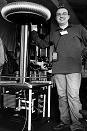
Here is a dental x-ray head, exposing a connector with 4 pins: Measuring them led to nothing, so I had to open the case, save the nice paraffin oil, check the wires, then put everything back together.
The high voltage transformer has a 220V primary and two secondaries: a HV one and the filament secondary According to the numbering presented in the first picture, 1 & 2 is are the mains pins (220V) connected to the HV transformer primary. Pin 3 is one of the filament connections, floating above ground. Placing a resistor between pin 3 and ground will limit the current fed to the filament, and so the temperature of the filament and the intensity of the x-ray output. I have no idea what pin 4 is, but I assume it is a tap on the HV secondary used to measure the output. Something similar to this:
Everything was put back and case resoldered. Finally I applied a black paint layer, that looks good
After putting everything together and connecting the head as presented here, it appears to work, but the pin 4 arcs to ground: The bulb was added between pin 3 and ground to limit the filament current and greatly reduce the x-rays output. A sensitive geiger dosimeter (RADEX 1706) would detect the emission only when placed in front of the outputting window.
To stop the arc, as a temporary solution , I placed a HV 1K resistor from pin 4 to ground as shown in the last picture. The frontal window exposes an aluminum disc of about 0.8 mm width.
The question is: Does anyone recognize this head or has any info on what the pin 4 is?
Registered Member #56
Joined: Thu Feb 09 2006, 05:02AM
Location: Southern Califorina, USA
Posts: 2445
Are you sure that the pin is not simply the return for the high voltage coil? It seems logical that they would route it through the connector so that you could put in a resistor (1k is a good value) to measure the current flowing through the tube.
Registered Member #1938
Joined: Sun Jan 25 2009, 12:44PM
Location: Romania
Posts: 699
It is possible . I asked hoping someone would recognize this head model. For now it works as it is, and I don;t have plans for making a fancy circuit for it, as I would only need it on rare occasions , for "debugging" black boxes.
Registered Member #33
Joined: Sat Feb 04 2006, 01:31PM
Location: Norway
Posts: 971
Nice shot. Do you have some details on the type of screen and camera used, voltage, current, distance, iso and exposure time?
The circuit is most likely very similar to the attached image, minus the separate filament transformer. When x-ray tubes are used in self-rectified mode, the current sensing resistor needs to be in series with the secondary instead of between the center-tap and ground.
Registered Member #1938
Joined: Sun Jan 25 2009, 12:44PM
Location: Romania
Posts: 699
Hi Anders,
Judging from the internals, I'd rather go for the attached diagram . Do you feel it looks like a common topology? Also the pics show the secondary as a single block, what do you think? In my setup, Pin 3 is connected to ground for maximum filament temperature. Pin 4 is connected to ground , via a 1K resistor. Before the 1K resistor, pin4 was arcing to the case, like shown in the pictures above.
Registered Member #122
Joined: Fri Feb 10 2006, 12:55PM
Location: Milano Italy
Posts: 148
This is a really nice object!
You can use it for build a really compact machine capable of both radiograpy (powerful shots for really short times only)and radioscopy (less powerful shots, but capable of few tens of seconds exposures), you only need a proper value resistor in series of pin 3 and a switch without any external transformer or any other bulk equipment!
This site is powered by e107, which is released under the GNU GPL License. All work on this site, except where otherwise noted, is licensed under a Creative Commons Attribution-ShareAlike 2.5 License. By submitting any information to this site, you agree that anything submitted will be so licensed. Please read our Disclaimer and Policies page for information on your rights and responsibilities regarding this site.


 Dental X-Ray head