If you need assistance, please send an email to forum at 4hv dot org. To ensure your email is not marked as spam, please include the phrase "4hv help" in the subject line. You can also find assistance via IRC, at irc.shadowworld.net, room #hvcomm.
Support 4hv.org!
Donate:
4hv.org is hosted on a dedicated server. Unfortunately, this server costs and we rely on the help of site members to keep 4hv.org running. Please consider donating. We will place your name on the thanks list and you'll be helping to keep 4hv.org alive and free for everyone. Members whose names appear in red bold have donated recently. Green bold denotes those who have recently donated to keep the server carbon neutral.
Special Thanks To:
Aaron Holmes
Aaron Wheeler
Adam Horden
Alan Scrimgeour
Andre
Andrew Haynes
Anonymous000
asabase
Austin Weil
barney
Barry
Bert Hickman
Bill Kukowski
Blitzorn
Brandon Paradelas
Bruce Bowling
BubeeMike
Byong Park
Cesiumsponge
Chris F.
Chris Hooper
Corey Worthington
Derek Woodroffe
Dalus
Dan Strother
Daniel Davis
Daniel Uhrenholt
datasheetarchive
Dave Billington
Dave Marshall
David F.
Dennis Rogers
drelectrix
Dr. John Gudenas
Dr. Spark
E.TexasTesla
eastvoltresearch
Eirik Taylor
Erik Dyakov
Erlend^SE
Finn Hammer
Firebug24k
GalliumMan
Gary Peterson
George Slade
GhostNull
Gordon Mcknight
Graham Armitage
Grant
GreySoul
Henry H
IamSmooth
In memory of Leo Powning
Jacob Cash
James Howells
James Pawson
Jeff Greenfield
Jeff Thomas
Jesse Frost
Jim Mitchell
jlr134
Joe Mastroianni
John Forcina
John Oberg
John Willcutt
Jon Newcomb
klugesmith
Leslie Wright
Lutz Hoffman
Mads Barnkob
Martin King
Mats Karlsson
Matt Gibson
Matthew Guidry
mbd
Michael D'Angelo
Mikkel
mileswaldron
mister_rf
Neil Foster
Nick de Smith
Nick Soroka
nicklenorp
Nik
Norman Stanley
Patrick Coleman
Paul Brodie
Paul Jordan
Paul Montgomery
Ped
Peter Krogen
Peter Terren
PhilGood
Richard Feldman
Robert Bush
Royce Bailey
Scott Fusare
Scott Newman
smiffy
Stella
Steven Busic
Steve Conner
Steve Jones
Steve Ward
Sulaiman
Thomas Coyle
Thomas A. Wallace
Thomas W
Timo
Torch
Ulf Jonsson
vasil
Vaxian
vladi mazzilli
wastehl
Weston
William Kim
William N.
William Stehl
Wesley Venis
The aforementioned have contributed financially to the continuing triumph of 4hv.org. They are deserving of my most heartfelt thanks.
Registered Member #30
Joined: Fri Feb 03 2006, 10:52AM
Location: Glasgow, Scotland
Posts: 6706
It's a series circuit, so it doesn't matter if you put the current sensor "before" or "after" the tank capacitor, the current flowing through it is the same.
Registered Member #76
Joined: Thu Feb 09 2006, 10:04AM
Location: Hemer, Germany
Posts: 458
i dont know, its the first drsstc i spend so much effort into to make it look good and now, nothing works, dissapointing. some parts arrived today, jeah and some 400volt tvs,, i made a pcb wich is a 1:1clone of steve wards circuit he describes on his drsstc guide, maybe this will do the trick, but i dont know, i used my version of this driver with success in my drsstc6, the only thing i really changed is to use a lm393 instead of an lm311 and i changed a part of the overcurrent logic with a 7400 to get away from this funny rc combination, and it works perfect, on the first german teslathon this year i had an interrupter failure which made my interrupter go like mad with on times of about 2mS ,and i ran the coil for minutes with this settings without blowing parts, the sparks made a rattling loud noise and were brighter and longer i ever seen before, hehe okay blew some 10A fuses but no blown igbts, so really my logic works. im not sure but i think its the high side cap charging circuit. but i dont know, its very simple, i use an lm393 with an 1/100 voltage divider to measure the cap voltage. when power switch is on the cap charges via 190ohms resistors until i get 250volts dc on the cap, then the comparator switches a relais on via some bc238 transistors .the relais bridges the charging resistors, .i have 2 leds to show the status, charging and ready, nothing too special. okay its a high side charging circuit cause the negatives of the cap and the comparator are the same, but the circuit is an stand alone with own bridge rectifier (but same transformer)so it should have nothing to do with the driver causing the bridge to go boom.
Registered Member #154
Joined: Sun Feb 12 2006, 04:28PM
Location: Westmidlands, UK
Posts: 260
Hi Reaching,
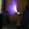
In the picture of your lay out, you use a lot of wire (inductance) from your buss cap to your bridge, could induce spikes at higher buss voltage and kill your IGBT's? Plus you said that you don't use any tvs on your bridge.
Registered Member #76
Joined: Thu Feb 09 2006, 10:04AM
Location: Hemer, Germany
Posts: 458
but that wouldnt pop a bridge just in time when you switch on the interrupter, btw never had any problems with voltage spikes etc, and i use 12mm² wire, thats a low inductance compared to my other designs.
Registered Member #154
Joined: Sun Feb 12 2006, 04:28PM
Location: Westmidlands, UK
Posts: 260
Do you use a variac to slowly increase buss voltage? its a good idea to use one whilst de-bugging your system. If fuses blow at lower buss voltage, problem could be GDT phasing problem, if things work ok at lower buss voltage but start blowing fuses/IGBT's at higher voltage, problem could be spike problem.
I had problems with my UCC driver ic's causing all weird and wonderfull problems when i built my last small DRSSTC.
Registered Member #79
Joined: Thu Feb 09 2006, 11:35AM
Location: Arkansas
Posts: 673
Reaching, if you don't have a variac, you can make one out of an MOT. It's not "linear" it's really more of a tapped transformer, but I rewound one and made a switch bank that canceled out each lower switch (not hard if you think about it). I was going to put it on my site because it worked great, but I acidentally shorted it one day and killed it. Soon after I got a real variac so I didn't pursue it any longer. I'll see if I can dig up a picture if you want.
The advantage of this is you can have whatever-power variac you want for really cheap, however, it's not continuous. (IE. current is shut off briefly during switching.)
Registered Member #76
Joined: Thu Feb 09 2006, 10:04AM
Location: Hemer, Germany
Posts: 458
i have a variac rated 2,2kW but thats not the question here. why should i put in a variac to slowly bring up the voltage until the igbts blow upt the third time,.. i know there is something wrong in my circuit or whatever and i want to find the failure until i blow more igbts. btw i have to build a new bridge cause i have only 2 40n60 miniblocks left, and the others are already build in in my other drsstcs. but i have 10 of the to 247 pack 40n60 but without diodes , i think i can use them when i can find some usable fast freewheeling diodes such as mur1560 or whatever. seems that nothing would work i build a new driver (exact 1:1 clone of steve wards drsstc guide driver) but it wont work properly, i know its not a failure in steves circuit, more a failure in my pcb but i spend 2 hours of debugging and didnt found the failure. maybe someone of you had the same problem. i tested the driver with a signal generator at the feedback input and with an interrupter on the interrupter input. the only thing the driver makes is to switch the 100khz feedback signal through the driver ics, the interrupter signal is lost on pin 7 of 74hc109,,,,
Registered Member #154
Joined: Sun Feb 12 2006, 04:28PM
Location: Westmidlands, UK
Posts: 260
Hi Reaching,
so you have no interrupter signal at pin 7?
have you chosen the correct values of R9 and C14? this delay RC should be chosen acording to your coils running frequency. I think Steve uses a 1nf and a 22k for his coils frequency.
Just a thought.
On second thoughts.....ignor the above, even if you had the wrong values, an interrupter signal should still be present at pin 7 of your flip flop ic.
Registered Member #76
Joined: Thu Feb 09 2006, 10:04AM
Location: Hemer, Germany
Posts: 458
yeah i know, i build several types of flip flop sync circuits so im somewhat confirm with them, but i cloned steves circuit 1:1 and it doesnt work, i checked everything 5 times ,looked for shorts on the pcb etc but found nothing, the circuit is exactly that in the shematic and it doesnt work, i tried out 5 different 74hc109 different 74hc14 different 555s ucc chips etc but nothing, i dont know the reason. on pin 1 of the 74hc109 is the inverted interrupter signal, pin 2 and 3 are connected to +5volt pin 4 is the feedback signal, pin 5 is the noninverted interrupter signal and on pin 6 and 7 is nothing,sometimes the right signal but only 0,5volts amplitude, seems like a pin7 short on the pcb without a short on the pcb, lol, already build the 74hc109 on a breadboard and connected pin for pin by showing the current draw of the circuit which is nearly 200ma without a load and the 74hc109 gets warm thats not normal i know. ahh i dont know
Registered Member #146
Joined: Sun Feb 12 2006, 04:21AM
Location: Austin Tx
Posts: 1055
All ICs have proper 5V measured at the pins? I really cant imagine what the problem might be unless its simply a bad connection somewhere. Ive had bad sockets before, where some pins didnt make contact, and id spend hours trying to figure out what went wrong. Maybe use a continuity checker on each pin of the IC to the trace on the PCB. Many of the problems i encounter with my PCBs is either forgetting to supply power or ground to the chip (its the most basic thing, so i tend to overlook it of course).
This site is powered by e107, which is released under the GNU GPL License. All work on this site, except where otherwise noted, is licensed under a Creative Commons Attribution-ShareAlike 2.5 License. By submitting any information to this site, you agree that anything submitted will be so licensed. Please read our Disclaimer and Policies page for information on your rights and responsibilities regarding this site.


 Weekend DRSSTC