If you need assistance, please send an email to forum at 4hv dot org. To ensure your email is not marked as spam, please include the phrase "4hv help" in the subject line. You can also find assistance via IRC, at irc.shadowworld.net, room #hvcomm.
Support 4hv.org!
Donate:
4hv.org is hosted on a dedicated server. Unfortunately, this server costs and we rely on the help of site members to keep 4hv.org running. Please consider donating. We will place your name on the thanks list and you'll be helping to keep 4hv.org alive and free for everyone. Members whose names appear in red bold have donated recently. Green bold denotes those who have recently donated to keep the server carbon neutral.
Special Thanks To:
Aaron Holmes
Aaron Wheeler
Adam Horden
Alan Scrimgeour
Andre
Andrew Haynes
Anonymous000
asabase
Austin Weil
barney
Barry
Bert Hickman
Bill Kukowski
Blitzorn
Brandon Paradelas
Bruce Bowling
BubeeMike
Byong Park
Cesiumsponge
Chris F.
Chris Hooper
Corey Worthington
Derek Woodroffe
Dalus
Dan Strother
Daniel Davis
Daniel Uhrenholt
datasheetarchive
Dave Billington
Dave Marshall
David F.
Dennis Rogers
drelectrix
Dr. John Gudenas
Dr. Spark
E.TexasTesla
eastvoltresearch
Eirik Taylor
Erik Dyakov
Erlend^SE
Finn Hammer
Firebug24k
GalliumMan
Gary Peterson
George Slade
GhostNull
Gordon Mcknight
Graham Armitage
Grant
GreySoul
Henry H
IamSmooth
In memory of Leo Powning
Jacob Cash
James Howells
James Pawson
Jeff Greenfield
Jeff Thomas
Jesse Frost
Jim Mitchell
jlr134
Joe Mastroianni
John Forcina
John Oberg
John Willcutt
Jon Newcomb
klugesmith
Leslie Wright
Lutz Hoffman
Mads Barnkob
Martin King
Mats Karlsson
Matt Gibson
Matthew Guidry
mbd
Michael D'Angelo
Mikkel
mileswaldron
mister_rf
Neil Foster
Nick de Smith
Nick Soroka
nicklenorp
Nik
Norman Stanley
Patrick Coleman
Paul Brodie
Paul Jordan
Paul Montgomery
Ped
Peter Krogen
Peter Terren
PhilGood
Richard Feldman
Robert Bush
Royce Bailey
Scott Fusare
Scott Newman
smiffy
Stella
Steven Busic
Steve Conner
Steve Jones
Steve Ward
Sulaiman
Thomas Coyle
Thomas A. Wallace
Thomas W
Timo
Torch
Ulf Jonsson
vasil
Vaxian
vladi mazzilli
wastehl
Weston
William Kim
William N.
William Stehl
Wesley Venis
The aforementioned have contributed financially to the continuing triumph of 4hv.org. They are deserving of my most heartfelt thanks.
Registered Member #76
Joined: Thu Feb 09 2006, 10:04AM
Location: Hemer, Germany
Posts: 458
okay, this project grew up yesterday, cause i have sooo many parts of my old drsstcs and experimental primaries etc liying around that i decided to use them in a quick but not dirty drsstc build and tested in a weekend. yesterday i searched for parts to use and came up with some really nice parts i found, such as
fullbridge of 40n60 igbts (almost finished) primary with 6mm copper tubing and 7turns, inner diameter of 21cm, height of 10cm, strikerail etc (finished) a nice hdpe case i build a few weeks ago already with a 80mm fan installed (finished) 10x wima fkp1 caps 100nf 1,6kV for a mmc of 300nF 3,2kV DC (finished) some nice high frequency cases yesterday i finished the driver (from my new drsstc6) and tested it ok finished the mmc and the 1/1000 current transformer today.
still have to build the 1/140 feedback transformer and put it in a shielded case , have to wind the 2 gdts for the bridge and add some decoupling caps, tranzorbs etc to make the bridge work. here are a few pics.
(here is what i started with yesterday) (finished driver in the small package,hehe) (finished mmc, double sided pcb full tinned) (the 1to1000 current transformer in a hf box
more to come very soon, still have to finish the bridge, the secondary and the toroid secondary will be a 11x40 or 11x35cm wound with 0,17mm wire to give a fres of approx 90khz with a 10x30 toroid, but i doubt i can finish them this weekend cause i want a very nice toroid and that needs some time
Registered Member #76
Joined: Thu Feb 09 2006, 10:04AM
Location: Hemer, Germany
Posts: 458
small update, started to wire the things up as professional as i can, that needs some time and i have to build up a comparator charging circuit for the electrolytic cap too. dont want to use this old charging circuit i have on hand, its too stoneage like but things seems to do great and this will be a very powerful small portable drsstc when im finished. heres a pic of the current status
heres the front
okay, not finished this weekend, but the next weekend is only 5 days away, hrhr
more updates
working on a comparator charging circuit for the 2200yf electrolytic cap. status leds for charging and ready, seems to work fine on my breadboard, now im on building it on a pcb. when it works then i can finish the complete electronics today and can make first decisions on how to make a nice toroid and secondary
update
finished the charging circuit, it charges the cap up to 250volts dc via 2 charging resistors 190ohm 8 watt and when the cap reaches 250volts a relay bridges the charging resistors, so i can pull up the bridge relatively smooth without tripping the breaker while loading up the big bridge cap. therefore there are 2 leds one shows the charging status the second led goes on when the cap is full (~310volt dc) there are 2 switches for this device, one to switch it on and the second to switch the bridge rectifier on and start the charging , when the switches are off the cap discharges automatically through a another resistor
Registered Member #76
Joined: Thu Feb 09 2006, 10:04AM
Location: Hemer, Germany
Posts: 458
new update
had a failure in my charging circuit due to a bad voltage divider but now it works fine and everything does like it should. finished the electronics today, and tommorow i can start winding the secondary. then i can do the first low voltage testruns and when everything works i can have first full power tests on saturday or sunday. cant wait to see this beast in action.
here are two pics of the current status
(okay not industrial standard but better than nothing)
Registered Member #76
Joined: Thu Feb 09 2006, 10:04AM
Location: Hemer, Germany
Posts: 458
started doing some first low voltage resonant tests and got dissapointed cause the thing wont start to oscillate, but no problem, i found the failure on my driver pcb, i have 2 wrong turned diodes which leads the feedback signal to ground. now i have to change the diodes and hopefully the thing will do its job. more info to come soon, and a few scopeshots if everything works after fixing the failure
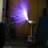
started doing first testruns and got first light today with around 50volts input some 10cm discharges. after fixing some problems with my driver i can now do first tests on mains voltage, hope that doesnt end in a disaster
update
yeah, and it ended in a disaster and i cant find the failure, my fullbridge is just popping away when i test it on mains voltage. i thought it was the driver powersupply which was not enough smoothed , after fixing this i tested again, but the same failure, it is like the bridge is just turned on and ends like a bakon , . my thought is the feedback ct which has only 115turns , but why does this thing work on 50volts with all signals ok but not on mains voltage? now im on building a new driver version with (almost the same like steve ward describes in his drsstc guide) hope the 1/1000 ct´s will fix the problem, hopefully,
Registered Member #146
Joined: Sun Feb 12 2006, 04:21AM
Location: Austin Tx
Posts: 1055
Seems unlikely that the CTs would be a problem. Ive used 1:100 CTs for feedback in the past, they seemed to work just the same as the 1:33 to 1:33 CT arrangement that ive been using more recently.
You might want to make sure you dont have some voltage transients killing the IGBTs.
Registered Member #55
Joined: Thu Feb 09 2006, 04:56AM
Location:
Posts: 149
I have used 1:100cts for the feedback circuits on my past two coils and they work fine. I still use cascaded CTs for my current sense transformers becasue using a low value loading resistor casued all kinds of problems with faulty triggering. Your Cts should be fine. Could your clamping schema for feedback Ct be faulted causing your 5V logic to fry? Have you checked the operation of your logic?
Registered Member #76
Joined: Thu Feb 09 2006, 10:04AM
Location: Hemer, Germany
Posts: 458
yeah, logic and everything is fine. the only thing i wondered about was the feedback which sometimes stops at 20volt input on the bridge when i turn the on time higher or the off time lower, this problem is gone when i use 50volts on the bridge. and i dont think i kill the igbts in cause of voltage transients, okay i have not tvs on the bridge, but i never used them in my 6 drsstcs i build before, so the problem is a secret for me, .im very sure that it has to do with my high side cap charging circuit or with my driver (its a revised version of my drsstc6 controller which is a revised version of steve wards drsstc3 driver)
now a question, where should i put the ct and feedback transformer in and how does it behave , after the mmc or before the mmc ?? okay the current transformer should be mounted after the mmc to catch the real pulsed amperage but where does the feedback ct "work" better?. its like a noobish question for one who already build 6 drsstcs but 4 of them are secondary feedback which worked better for me than any primary feedback i tried so im in the thought to switch back to secondary base feedback with overcurrent protection. i never popped a fullbridge by switching mains on it and never fried any igbts during a testrun when i worked with secondary feedback which is so "bad for the igbts" cause of no zero current switching etc, i dont share this opinion after 4 of my good igbts died so fast
Registered Member #55
Joined: Thu Feb 09 2006, 04:56AM
Location:
Posts: 149
I always put the feedback CT before the MMC. If your logic is ok, I would suspect it has something to do with your gate drive, did you ever get a chance to use a scope and check for shoot through?
This site is powered by e107, which is released under the GNU GPL License. All work on this site, except where otherwise noted, is licensed under a Creative Commons Attribution-ShareAlike 2.5 License. By submitting any information to this site, you agree that anything submitted will be so licensed. Please read our Disclaimer and Policies page for information on your rights and responsibilities regarding this site.


 Weekend DRSSTC


 , . my thought is the feedback ct which has only 115turns , but why does this thing work on 50volts with all signals ok but not on mains voltage?