If you need assistance, please send an email to forum at 4hv dot org. To ensure your email is not marked as spam, please include the phrase "4hv help" in the subject line. You can also find assistance via IRC, at irc.shadowworld.net, room #hvcomm.
Support 4hv.org!
Donate:
4hv.org is hosted on a dedicated server. Unfortunately, this server costs and we rely on the help of site members to keep 4hv.org running. Please consider donating. We will place your name on the thanks list and you'll be helping to keep 4hv.org alive and free for everyone. Members whose names appear in red bold have donated recently. Green bold denotes those who have recently donated to keep the server carbon neutral.
Special Thanks To:
Aaron Holmes
Aaron Wheeler
Adam Horden
Alan Scrimgeour
Andre
Andrew Haynes
Anonymous000
asabase
Austin Weil
barney
Barry
Bert Hickman
Bill Kukowski
Blitzorn
Brandon Paradelas
Bruce Bowling
BubeeMike
Byong Park
Cesiumsponge
Chris F.
Chris Hooper
Corey Worthington
Derek Woodroffe
Dalus
Dan Strother
Daniel Davis
Daniel Uhrenholt
datasheetarchive
Dave Billington
Dave Marshall
David F.
Dennis Rogers
drelectrix
Dr. John Gudenas
Dr. Spark
E.TexasTesla
eastvoltresearch
Eirik Taylor
Erik Dyakov
Erlend^SE
Finn Hammer
Firebug24k
GalliumMan
Gary Peterson
George Slade
GhostNull
Gordon Mcknight
Graham Armitage
Grant
GreySoul
Henry H
IamSmooth
In memory of Leo Powning
Jacob Cash
James Howells
James Pawson
Jeff Greenfield
Jeff Thomas
Jesse Frost
Jim Mitchell
jlr134
Joe Mastroianni
John Forcina
John Oberg
John Willcutt
Jon Newcomb
klugesmith
Leslie Wright
Lutz Hoffman
Mads Barnkob
Martin King
Mats Karlsson
Matt Gibson
Matthew Guidry
mbd
Michael D'Angelo
Mikkel
mileswaldron
mister_rf
Neil Foster
Nick de Smith
Nick Soroka
nicklenorp
Nik
Norman Stanley
Patrick Coleman
Paul Brodie
Paul Jordan
Paul Montgomery
Ped
Peter Krogen
Peter Terren
PhilGood
Richard Feldman
Robert Bush
Royce Bailey
Scott Fusare
Scott Newman
smiffy
Stella
Steven Busic
Steve Conner
Steve Jones
Steve Ward
Sulaiman
Thomas Coyle
Thomas A. Wallace
Thomas W
Timo
Torch
Ulf Jonsson
vasil
Vaxian
vladi mazzilli
wastehl
Weston
William Kim
William N.
William Stehl
Wesley Venis
The aforementioned have contributed financially to the continuing triumph of 4hv.org. They are deserving of my most heartfelt thanks.
Registered Member #325
Joined: Fri Mar 17 2006, 12:42AM
Location: Turku, Finland
Posts: 55
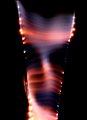
Hi, I recently scavenged a bunch of fiber-coupled telecom lasers like this:
They say ERICSSON PGT 2030/3DS, but I have not been able to locate a datasheet. I think they are pretty old (early 1990s or late 1980s?). I guess they are 1550 nm or something like that (far IR). The package is similar to a DIP-14 IC, and two of the pins are clearly connected to the case. I guess the remaining pins have the following functionality:
LD (anode and cathode)
PD (anode and cathode)
TEC
Modulator
Thermistor?
Any idea how to find out what the pins do without access to a datasheet? Or any clues where I could find a datasheet? I have some of the original driver boards but they are pretty smashed up and difficult to make sense of. Thanks for your help.
EDIT: What kind of output power is to be expected from these? 100mw? The warning sticker says class 3B which covers a rather broad range of output?
Registered Member #325
Joined: Fri Mar 17 2006, 12:42AM
Location: Turku, Finland
Posts: 55
Many thanks for that, now at least I know how much power to feed it! I have four of this specific type, I might have a go at dissecting one, though I'm not sure if I could make much sense out of it when open
Registered Member #56
Joined: Thu Feb 09 2006, 05:02AM
Location: Southern Califorina, USA
Posts: 2445
My best guess would be that the pins connected to the case are the + of the laser (that is pretty much the standard)
From there, I would carefully apply power to each of the other pins... Use like 1v at 3ma to see which ones are connected to the case (I would expect the laser and possible the sense). This narrows down the number of possible pins for the laser.
Now use a supply limited at 30ma (or add a resistor to limit current around there) and carefully apply voltage to the remaining pins. One of them should show very little current draw up to a volt or 2, then should suddenly draw the full 30ma over a range of few tenths of a volt. This is the laser XD
From there... Try taking a volt meter from the case to the remaining pins, one of them should read a voltage proportional to the output power...
Once you have the laser/monitor... Measuring the power using the voltmeter slowly give it more current, and find where the max output occurs (it should be around or below 30ma if the datasheet is right). Back of the current to give 10% less output power (just to be safe) and record that number. Always use a power supply rated for that. Be careful though, the temp sensor might also be attached to the case. The power sensor will have a very fast response to the to diode current, while the temp sensor will have a much slower output. Don't mix it up, or you will just keep adding power until you blow up the diode
At this point, I would expect there to be a tec and a temp sensor. The tec will act like a normal resistor... But the temp sensor will too, the difference will be the value. The tec should draw about an amp at a volt or 2, while the temp will only draw a few ma it that. If you find both, try monitoring the resistance of the temp sensor while giving the tec some power... You should see the temp sensor's resistance vary with tec power. Now remember that the temp sensor will *probably* read a resistance inversely to temp, so as the resistance drops you are heating the diode...
I would say with a 99.9% accuracy that doesn't have a modulator (my dad grows the lasers for a living, so I have seen more than my share of them).
From there, you can find the optimal temp for the laser... Hook up a voltmeter on the power sensor and give it a regulated current (the amount doesn't really matter, go for the value you get earlier) and put a ohmmeter across the temp sensor. Then in theory, you should see the resistance across the temp sensor slowly dropping (if it is slowly rising them you got a weird temp sensor, and its resistance is directly proportional to the temp... so reverse everything about the tec accordingly). Now give the tec a little power... You should see the temp sensor's rate of change differ... If it slows down or reverses you found the direction to cool the diode. If it goes faster it is the direction that heats the diode... Now look back at the meter and heat the diode a little. If the power decreases then cool the diode. Mess with it until you find the max power... Now record the value of the temp sensor, this is where you are supposed to run the diode.
So at this point you should have a pretty complete pinout, the operating current/voltage of the diode, the operating temp of the diode (if you want the value in a real number like degrees C, power everything down and let it sit for a few hours to normalise, then slowly heat/cool the module until you get the same reading for the temp sensor), and the relative power output. What more could you want?
A few things...
I doubt that it is only 2mw, since it is at an eyesafe wavelength and rated class IIIB... Seems like you should get at least 5mw Also that case should be able to dissipate a few watts, so unless that is just the power of the tec... I would also bolt it down to a good sized heat sink...
I have a calibrated power meter that has the same connector if you want me to calibrate one of your lasers... From there you could create a little adapter to couple one into a phototdiode as a power meter... Or I could just do all of them I have to warn you, it reads in DB, so I don't know how that would convert to mw...
Registered Member #325
Joined: Fri Mar 17 2006, 12:42AM
Location: Turku, Finland
Posts: 55
Thanks for the detailed instructions, I will try to identify the pins this way. I'm just using a photodiode and voltmeter to see if anything is coming out of the fiber, I have no way of measuring the power.
Registered Member #30
Joined: Fri Feb 03 2006, 10:52AM
Location: Glasgow, Scotland
Posts: 6706
There is no standard regarding which end of the laser diode is connected to the case. Some are grounded anode, some grounded cathode, and some floating. I design drivers for telecom lasers in my day job, and this causes a huge headache.
The temperature sensor will almost certainly be a "10k NTC" thermistor. It measures 10k at 25ºC and decreases as it gets hotter.
The TEC will measure as a very low resistance (an ohm or two) between two pins.
There won't be a modulator in the case, but there may be a "Bias tee". This is a little inductor and DC blocking cap, to allow the DC drive current and the modulation to be fed in on different pins.
Be careful what you use to buzz the circuit out. I heard that the ohms or diode test range on some meters can kick out enough voltage to destroy the laser diode if you reverse bias it, although I've never destroyed one this way myself.
The IR sensitive cards used for testing TV remotes should show the output of a laser like this. A digital or TV camera probably won't, though. This is a low powered 1310nm laser (a milliwatt or two) and it's really pretty boring.
... I guess your power meter ought to read in dBm, not dB. (unless you pressed the "Relative" button some time.) That means dB relative to 1mW, so 0dBm is 1mW, +3dBm is 2mW, -3dBm is 0.5mW etc. If you ever see it reading +60dBm, you're about to get lasered in half Goldfinger style.
Registered Member #325
Joined: Fri Mar 17 2006, 12:42AM
Location: Turku, Finland
Posts: 55
Steve Conner wrote ...
This is a low powered 1310nm laser (a milliwatt or two) and it's really pretty boring.
Since it is fiber-coupled and has standard connectors, I was thinking of using it for controlling high-voltage contraptions such as tesla coils. Kind of like a smart chicken stick. I use my 500mw, 750mw and 1W diodes for the less boring stuff .
Registered Member #56
Joined: Thu Feb 09 2006, 05:02AM
Location: Southern Califorina, USA
Posts: 2445
The meter is designed for measuring the losses across a fiber, but it does have a dBm mode And it can handle up to 30dBm
The only way to be sure of everything would be to carefully (I am thinking dremel tool with a cutoff weel or a little carbide tip) remove the lid and trace out the connections... If you post a detailed pic we can probably figure it all out for you...
Registered Member #325
Joined: Fri Mar 17 2006, 12:42AM
Location: Turku, Finland
Posts: 55
Many thanks for that pinout! I fed 30 mA to the laser diode pins and I got a voltage across the PD, so it seems to be working. However, the light does not show up on my digital camera CCD (probably it is completely blocked by the IR filter), so I have yet to verify that something is coming out of the fiber. I'll try some photodiodes...
And yes, I don't think I will bother driving the TEC, since I just plan on using this as a "very high insulation optocoupler"
This site is powered by e107, which is released under the GNU GPL License. All work on this site, except where otherwise noted, is licensed under a Creative Commons Attribution-ShareAlike 2.5 License. By submitting any information to this site, you agree that anything submitted will be so licensed. Please read our Disclaimer and Policies page for information on your rights and responsibilities regarding this site.


 How to identify pins on telecom laser?


 Also that case should be able to dissipate a few watts, so unless that is just the power of the tec... I would also bolt it down to a good sized heat sink...
 I have to warn you, it reads in DB, so I don't know how that would convert to mw...

 And it can handle up to 30dBm