If you need assistance, please send an email to forum at 4hv dot org. To ensure your email is not marked as spam, please include the phrase "4hv help" in the subject line. You can also find assistance via IRC, at irc.shadowworld.net, room #hvcomm.
Support 4hv.org!
Donate:
4hv.org is hosted on a dedicated server. Unfortunately, this server costs and we rely on the help of site members to keep 4hv.org running. Please consider donating. We will place your name on the thanks list and you'll be helping to keep 4hv.org alive and free for everyone. Members whose names appear in red bold have donated recently. Green bold denotes those who have recently donated to keep the server carbon neutral.
Special Thanks To:
Aaron Holmes
Aaron Wheeler
Adam Horden
Alan Scrimgeour
Andre
Andrew Haynes
Anonymous000
asabase
Austin Weil
barney
Barry
Bert Hickman
Bill Kukowski
Blitzorn
Brandon Paradelas
Bruce Bowling
BubeeMike
Byong Park
Cesiumsponge
Chris F.
Chris Hooper
Corey Worthington
Derek Woodroffe
Dalus
Dan Strother
Daniel Davis
Daniel Uhrenholt
datasheetarchive
Dave Billington
Dave Marshall
David F.
Dennis Rogers
drelectrix
Dr. John Gudenas
Dr. Spark
E.TexasTesla
eastvoltresearch
Eirik Taylor
Erik Dyakov
Erlend^SE
Finn Hammer
Firebug24k
GalliumMan
Gary Peterson
George Slade
GhostNull
Gordon Mcknight
Graham Armitage
Grant
GreySoul
Henry H
IamSmooth
In memory of Leo Powning
Jacob Cash
James Howells
James Pawson
Jeff Greenfield
Jeff Thomas
Jesse Frost
Jim Mitchell
jlr134
Joe Mastroianni
John Forcina
John Oberg
John Willcutt
Jon Newcomb
klugesmith
Leslie Wright
Lutz Hoffman
Mads Barnkob
Martin King
Mats Karlsson
Matt Gibson
Matthew Guidry
mbd
Michael D'Angelo
Mikkel
mileswaldron
mister_rf
Neil Foster
Nick de Smith
Nick Soroka
nicklenorp
Nik
Norman Stanley
Patrick Coleman
Paul Brodie
Paul Jordan
Paul Montgomery
Ped
Peter Krogen
Peter Terren
PhilGood
Richard Feldman
Robert Bush
Royce Bailey
Scott Fusare
Scott Newman
smiffy
Stella
Steven Busic
Steve Conner
Steve Jones
Steve Ward
Sulaiman
Thomas Coyle
Thomas A. Wallace
Thomas W
Timo
Torch
Ulf Jonsson
vasil
Vaxian
vladi mazzilli
wastehl
Weston
William Kim
William N.
William Stehl
Wesley Venis
The aforementioned have contributed financially to the continuing triumph of 4hv.org. They are deserving of my most heartfelt thanks.
Registered Member #89
Joined: Thu Feb 09 2006, 02:40PM
Location: Zadar, Croatia
Posts: 3145
Well I dragged my mess out this morning for first, low-voltage run. It's a halfbridge one with steve ward's primary feedback circuit.
Voltage to halfbridge is filtered by one big 400V 1000uF cap and divided by two smaller 470uF 200V caps (there are also transzorbs, decoupling caps and mess).
I ran it on 30V (so I get 15V per igbt) but it just seems to be ''working'' on interrupter pulses, and secondary rings to some point where it lights neon bulb 5cm away.
Primary feedback CT cascade gives no signal at all, zero.
I really have no clue what could be happening, I tested the board bunch of times before and it seemsed to work perfectly with resistor-limited signal generator input.
Only thing I can guess is that primary current is simply way to low for such a cascade to feel it. Output of CT is at zero voltage all the time, and I need some 3V to trigger 74HC14 input
But If I add more input I thing I'l just blow something up because it will continue to work on interrupter frequency.
And from what I figured out it really should get running at 30V in...
Registered Member #75
Joined: Thu Feb 09 2006, 09:30AM
Location: Montana, USA
Posts: 711
What about using a higher input voltage but current limiting it (e.g. with a lightbulb), so you cannot blow up your IGBTs if it does not work? I am not a expert in current transformer, but I could well imagine that a transformer designed for 500A or so wont give much of a signal at only 5A.
Registered Member #146
Joined: Sun Feb 12 2006, 04:21AM
Location: Austin Tx
Posts: 1055
The coil should oscillate just fine at 15V or better applied to the bridge (mine usually oscillates with only 5V or so). Its designed so that even a few A on the primary of the CT will give plenty of signal (its a very high gain system).
Did you use an oscilloscope to verify that the feedback is staying at 0V? Do you detect a short on the CT input when the CT is disconnected? Also, you may need to *reverse* the phasing the the CT, by either passing it through the wire the other way around, or reversing the output leads.
Also, each IGBT sees the full supply voltage (its not divided because the transistors are in "series").
Registered Member #15
Joined: Thu Feb 02 2006, 01:11PM
Location:
Posts: 3068
What are the specifications of your current transformer? Assuming you have a 1000:1 transformer, you should have no problem getting a signal with even 5A of current. Remember, the transformer you have takes the sampled current and gives an secondary current equal to 1/1000th of the primary current. However, voltage is the inverse, and since you have no burden resistor in this circuit, the voltage can be quite high, hence the need for the clamping network. So, with even a 5A primary current signal, you should have ample voltage to drive your circuit.
In fact, you should get oscillation without even having power on the bridge circuit. This is what that initial buzzing sound you may get when you first plug in your circuit.
I suspect your polarity of your transformer may be reversed. Try doing that, and see if it makes a difference.
Registered Member #89
Joined: Thu Feb 09 2006, 02:40PM
Location: Zadar, Croatia
Posts: 3145
Of course I tried to reverse CT.
And output is scoped and completely dead, with just some fluctuations at few hundred milivolts.
I don't see why should I get anything, even close to 5A trougt the primary when it is running just on interrupter pulses. I would probably blow it up if I increased the voltage more.
(Interrupter 'enables' , inverting UCC goes low and uninverting high, and this pulses the pri mary without feedback starting to oscillate.)
Also, each IGBT sees the full supply voltage (its not divided because the transistors are in "series").
IGBT will see 300V; but it will switch only half of it because of voltage divider on primary.
Registered Member #15
Joined: Thu Feb 02 2006, 01:11PM
Location:
Posts: 3068
Using a scope trace your signals. Use a signal generator to input a 5V square wave at the primary current feedback input and trace this through your circuit. I think you'll probably find out why its not working.
Registered Member #146
Joined: Sun Feb 12 2006, 04:21AM
Location: Austin Tx
Posts: 1055
IGBT will see 300V; but it will switch only half of it because of voltage divider on primary.
Huh? When one IGBT is ON, the other is OFF, and has the entire supply voltage across it... end of story. I dont care about a "voltage divider" for the return of the primary circuit, its passing RF, so it all looks like a loop anyway (capacitors are low Z to RF).
There should be some noise at least on the output of the CT when the primary is pinged from the interrupter going HI.
I don't see why should I get anything, even close to 5A trougt the primary when it is running just on interrupter pulses. I would probably blow it up if I increased the voltage more.
Figure out the surge impedance of the primary, and use V=IZ, and that will give you exactly what the initial primary current would be from the very first pulse applied. My DRSSTCs have a surge Z around 6 ohms, so at 30V, thats 5A already.
What type of diodes are you using to clamp the CT? And what arrangement?
Registered Member #89
Joined: Thu Feb 09 2006, 02:40PM
Location: Zadar, Croatia
Posts: 3145
Huh? When one IGBT is ON, the other is OFF, and has the entire supply voltage across it... end of story. I dont care about a "voltage divider" for the return of the primary circuit, its passing RF, so it all looks like a loop anyway (capacitors are low Z to RF).
I guess my last post was somewhat confusing :P Never mind.
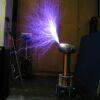
I tried to use antenna on feedback input, and got first light (or at least first oscillations).
With 30V input I got a 1cm streamer that could be drawn to a total of 2cm, when primary was around best tune. I also tried a signal generator (welcome back to Jimmy Hynes age ) but it was quite worse than antenna, and I needed double tuning...
I dug the whole bridge trying to debug the feedback, but it simply seems to be too weak. CT's are completely fine, All connections are good, and DRSSTC actually works (sort of 'works').
What type of diodes are you using to clamp the CT? And what arrangement?
Your arrangement, of course. two 5V zeners series with 4148's in reverse. ANt that seemed to clamp the antenna signal very well. I get a tiny streamer from the antena but it doesn't bother the circut at all.
Registered Member #15
Joined: Thu Feb 02 2006, 01:11PM
Location:
Posts: 3068
Sounds like you might have something out of whack. Check your primary / secondary resonant calculations again or measure the resonance and see if they are at least close together.
Registered Member #76
Joined: Thu Feb 09 2006, 10:04AM
Location: Hemer, Germany
Posts: 458
do you have clamping diodes on the secondary side of the CT, (i guess)? . if so, check the polarity of them, maybe they are wrong and let your signal going to gnd or so.
This site is powered by e107, which is released under the GNU GPL License. All work on this site, except where otherwise noted, is licensed under a Creative Commons Attribution-ShareAlike 2.5 License. By submitting any information to this site, you agree that anything submitted will be so licensed. Please read our Disclaimer and Policies page for information on your rights and responsibilities regarding this site.


 DRSSTC - cannot get oscillating


 ) but it was quite worse than antenna, and I needed double tuning...